- Community
- Get help and assistance with your Sonos system
- Speakers
- Dead Play:5 need schematics or tips
Dead Play:5 need schematics or tips
- July 28, 2016
- 208 replies
- 54329 views
- Contributor I
Play:5, manufacturing date sometime around 2009, is completely dead. No light in LED.
Found several cases of this online, but no solutions.
Does anyone have any knowledge about the problem, og better yet, schematics..
I mainly suspect problem in switch mode power supply. Have only done very basic measuring, but I find 220VAC on primary side, no power on secondary side. I think about ordering a mosfet, and/or a diode I suspect, but if I had schematics I could do some more pinpointing..
208 replies
- Lyricist I
- November 26, 2019
It was a qualified guess that the chip was defect
i found a video online of repair of a Sonos zp100
here he changed the usual suspects. One of was the small chip So I just did the same.
kind regards Anders
Thx Anders, I have a Sonos 5 (rev 1), with working rectifier (diodebro), fuse not blown, but not working. All caps seems to be fine on HV side so I guess that 2QS02G could be the problem child. Any proposals on where to get this chip easiest?
Mvh / Br
Jesper
- Lyricist I
- December 27, 2019
I’m trying to repair my Sonos play-5 gen-1. It has a problem that others have discussed but I’ve found no posts describing a repair. I have spoken with Sonos support and they confirmed the problem and offered a discounted replacement. I’d like to repair it. I have had good luck fixing Sonos power supply problems in the past. This play-5 seems to work. I can connect and stream music to it. The problem is that the volume is barely audible, even when set to max. There are no volume limits. There’s no distortion and both channels are working. Do any of you have suggestions on how I can further pursue this? The large caps and the rectifier measure correctly. Might this still be a power supply problem or is it more likely an amplifier issue? Any help would be appreciated.
Thanks
Lendy
- Contributor I
- January 13, 2020
Im going to piggyback onto this discussion to see if someone can help me out.
I have a Power supply issue with an issue on the switching side.
The unit has no power.
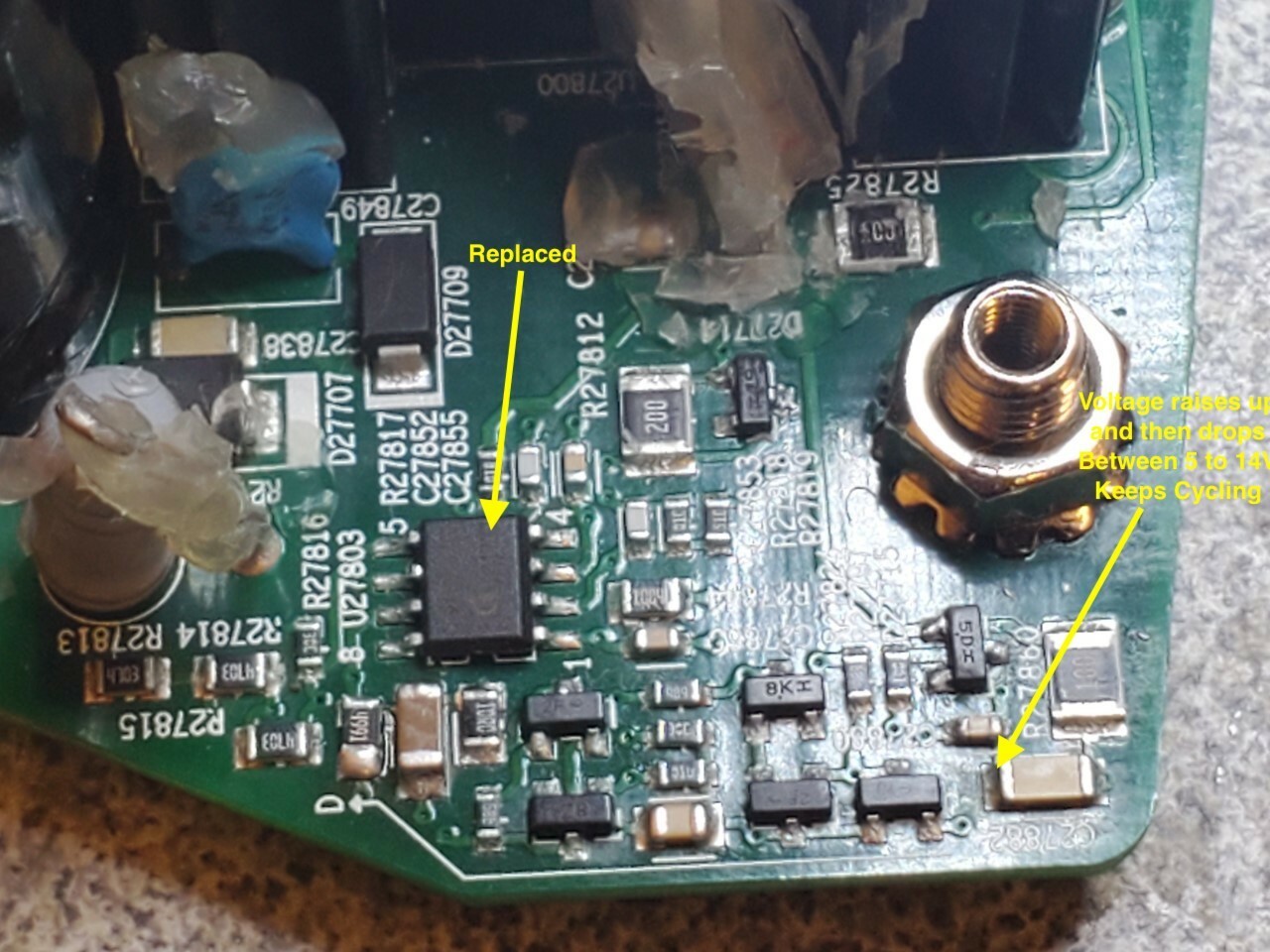
Replaced most of the power side caps, rectifier, fuse, FET IC Driver, FET, (Also smt 120K resistor near the rectifier was blown.)
I feel like im close, but I have this problem where the voltage starts at 5v ramps up to 15v and then bumps back down to 5v to repeat the process. Thought maybe a diode, but I cant find it.
When i remove the little 25v 100uf Cap between the two big filtering caps, the fluctuation goes away. Still get no power though.
Any Thoughts?
- Lyricist I
- January 20, 2020
Hi there,
I have the same problems (sorry for my bad english). One of the 120K smd resistors was defect, i place a new one but nothing happens.
On the 2 big elcos i measure 319 vdc but the little one of100uF is charging up to 19v en then back to 5v and thats repeating. When i measure with my scope i see the elco is charge and then recharge. I also replaced the 8p ic on the prim side. I checked al the components on the primair side but nothings wrong??
- Lyricist I
- January 27, 2020
Hi jpotts
It sounds as though the SMPS is trying to start-up, and then it shuts down again, and runds in this cycle. Maybe the control loop is broken
Have you tried to measure if there is any reponse at the optocoupler ? It’s located in the bottom right. Just to the right of the transformer. It’s a SHARP PC817..
- Lyricist I
- January 27, 2020
Hi all
I have been making some fault analysis at my own Play:5. Unfortunately the rectifier bridge and fuse is ok. The MOSFET driver at primary side is at least not shorted.
However the driver (FET, or BJT) at the secondary side is shorted between pin1 and pin3.
However I cannot figure out the tyoe, so it’s a little difficult. However a short circuit between legs is normally not something good ;-)
Or could I be tricked by the fact that the transformer might be connect to pin1 and pin3, so there is a DC short between pin1 and pin3 ?
- Lyricist I
- February 10, 2020
For what it’s worth, my pin1/3 on secondary side are also shorted. So either we both have the same problem or it’s supposed to be that way!
- Lyricist I
- March 10, 2020
Hello,
Maybe someone here can help me With my problem With my Play 5.
I have Some exploded smd capacitors/resistors/transistors on my board.
Might someone know the values of the following components:
C27852/C27855/D27714.
I found a helpful picture on this forum to know what the resistor values are.
Hoping someone can help me.
Thanks in advance.
CNS
- Lyricist I
- March 23, 2020
Hello please can someone tell me what components are in yelow fields? i can see G64 AN and 34AN A8 i cannot find anything. help me, i can donate you via paypal :)

- Lyricist I
- May 27, 2020
Hello,
nice Tread. Thanks for the details. I have a quite similar problem and Resistor 21817 burnt away. Can anyone please provide the value for this resistor?
BR
BATTA
- Lyricist I
- June 1, 2020
Hi all
I have been making some fault analysis at my own Play:5. Unfortunately the rectifier bridge and fuse is ok. The MOSFET driver at primary side is at least not shorted.
However the driver (FET, or BJT) at the secondary side is shorted between pin1 and pin3.
However I cannot figure out the type, so it’s a little difficult. However a short circuit between legs is normally not something good ;-)
Or could I be tricked by the fact that the transformer might be connect to pin1 and pin3, so there is a DC short between pin1 and pin3 ?
I have the same issue as you: measured short on the diode on the secondary side of the transformer. Yes, I checked for the more common AC-side failure: Input fuse is short, primary rectifier diodes measure good, but DC outputs pulse. Across the secondary-side toroid output filter inductor: L27721, I see pulsing DC levels measuring from GND (pins 2/5) to the two outputs (pins 1+6 and pins 3+4). I have desoldered (and partly muscled off) D27718, which is the DC rectifying diode in one of the two DC output circuits: ST STPS20150C. Pins 1 and 3 are shorted in the PCB by design. So basically the two diodes are in parallel. That matches what I see in the reference design of the ICE2QS02, which is the AC/DC Flyback switching controller. Hidden in the glue I also found D27705, which is the rectifying diode for the other output (pins 1 and 6 of L27721). It is fine also, too much glue to see any markings, but it has ~0.48Vfwd.
Though the behavior of the circuit looks like the controller is detecting a short on the secondary,tThe resistance to GND of the two outputs is good, my DMM measures constantly increasings resistance (i.e. a mostly capacitive load, with high resistance).
The transformer connection is hard to figure out. Pin 12 of the secondary is wired directly to the bulk caps, no diode in series, which isn’t the usual way. I think the diode (D27718) is in series with the GND connection on the other end of the same winding (pin 9). C27863 and R27057 (? I scratched the silk, but it is the big resistor embedded in glue) appear to just be a snubber circuit. But the other secondary winding (pins 7 and 11) I can’t figure out what they’re doing. The only place I find a connection is to R27808 in the feedback circuit.
Based on all of that, and not finding unexpected shorts in the DC/DC section, I think the problem is still in AC/DC. The Opto measured okay, at least as 2 diodes, but I don’t know that it is transmitting. If I bother working on this again, I guess I’d use the datasheet for ICE2QS02 to see if I was getting the expected feedback signal, and look at all 7 inputs to that part.
- Lyricist I
- June 1, 2020
BTW, if anyone has one of these boards working and can share what the voltages on the two outputs should be, that would help. That could be measured on C2781 and C2760 (the shorter two electrolytic caps on the AD/DC output, right next to the 2x25 header that goes up to the audio board).
- Lyricist I
- July 26, 2020
Following for any more information on a Sonos 5 that’s having power amp issues. I’m about to get mine apart and have determined only that it must be the power amp ( headphones out ok, aux in no output, speaker out very faint audio)
All guidance greatly appreciated! 😊
- Prominent Collaborator I
- August 10, 2020
Here is the best I’ve found on debugging Sonos Play:5 hardware issues:
https://sites.google.com/site/sonosdebug/power-topology
The author includes reverse-engineered information about jtag, serial port, connector, and the power supply (including a very helpful partial circuit diagram)!
There is nothing about the actual power amp. I have seen a few of these go bad and had only marginal success fixing them. One finding I did have was that a unit with missing bass had some of the driver ICs not having power. It turned out that some of the internal traces had burned out between the driver chips. I jumpered all of the power pins of the 6 ICs together (and all of the grounds too, for good measure), and it solved the problem.
If you have NO sound from the amplifier, then check the biases identified on the schematic and make sure that all of them (12v, 3.3V, 11.1V, 5V) are working.
- Lyricist III
- December 5, 2020
Here is the best I’ve found on debugging Sonos Play:5 hardware issues:
https://sites.google.com/site/sonosdebug/power-topology
The author includes reverse-engineered information about jtag, serial port, connector, and the power supply (including a very helpful partial circuit diagram)!
There is nothing about the actual power amp. I have seen a few of these go bad and had only marginal success fixing them. One finding I did have was that a unit with missing bass had some of the driver ICs not having power. It turned out that some of the internal traces had burned out between the driver chips. I jumpered all of the power pins of the 6 ICs together (and all of the grounds too, for good measure), and it solved the problem.
If you have NO sound from the amplifier, then check the biases identified on the schematic and make sure that all of them (12v, 3.3V, 11.1V, 5V) are working.
Hi Tim,
Is your play 5 having issue of very soft volume? Then you jumpered the traces and that fixed it?
- Lyricist I
- December 26, 2020
Hello,
My play 5 Gen 1 is acting a bit strange. when i power the speaker up it is working fine. when i restart (unplug an replug) the play 5, to move it for example. it won’t boot up. no lights no sound.
if i wait a couple hours it will boot up again. can this be a capacitor fault or a thermistor somewhere?
I desoldered all the capacitors and measured them, they seem te be okay. (capacity measurement only, no ESR)
my voltages are similar to Anders J. Instead of 0V i get between 0-2 volts which should be 11-12 and 24V. so i think the problem should be somewhere on the HV side.
Since the speaker wont turn on for a while could this mean the capacitors have to be empty first?
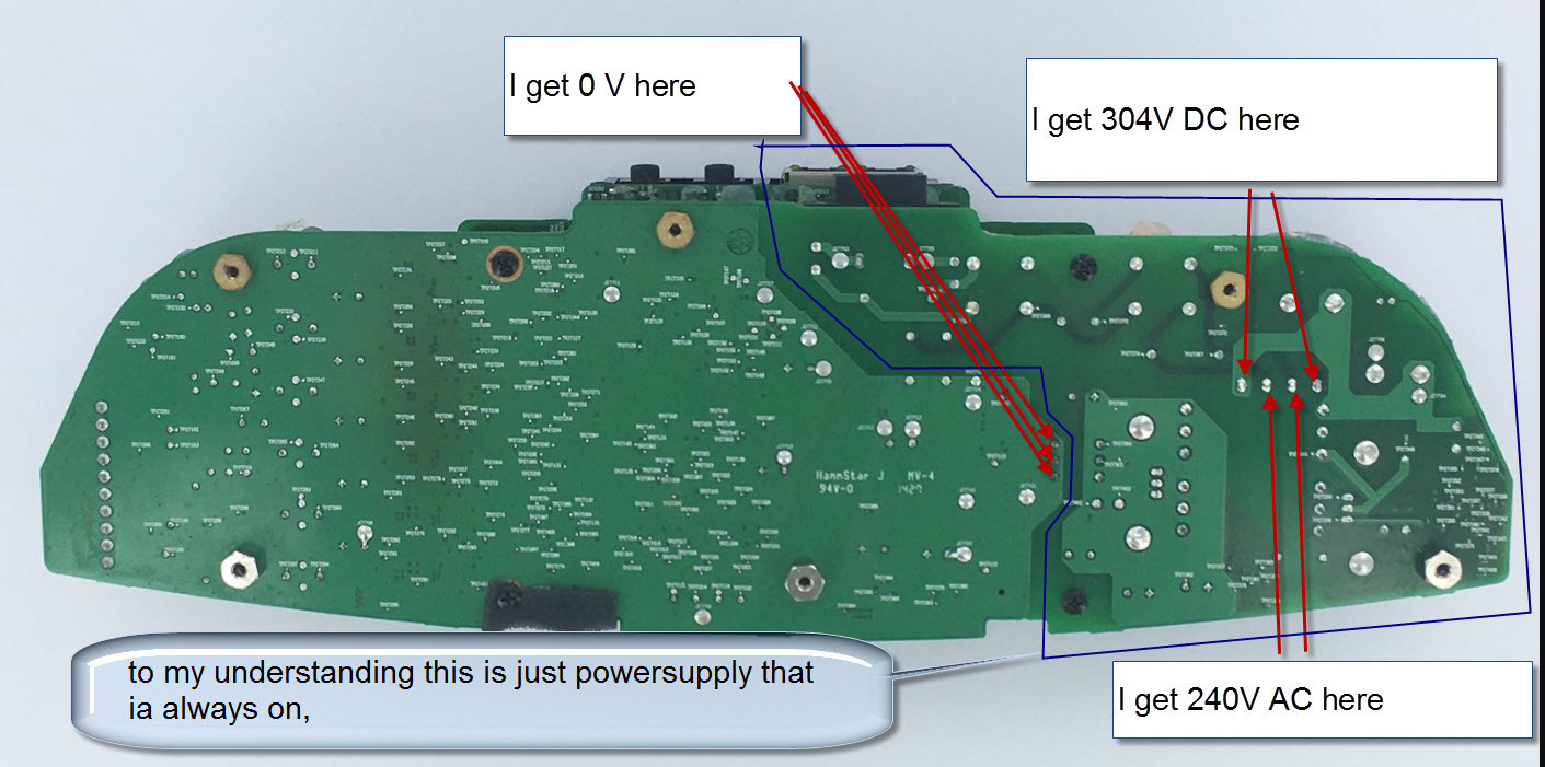
(picture from Anders J.)
- Contributor I
- January 10, 2021
God news my sonos Play 5 sings
I have changed the small chip that controls the mosfet
2QS02G
I also changed the rectifier MBR20150TC, but I do not thing it was defect. I broke it during the removal. I had to take it out to read the type. And therefore had to install a new one.
also changed 5 pcs electrolytic capacitors 820uf 35V
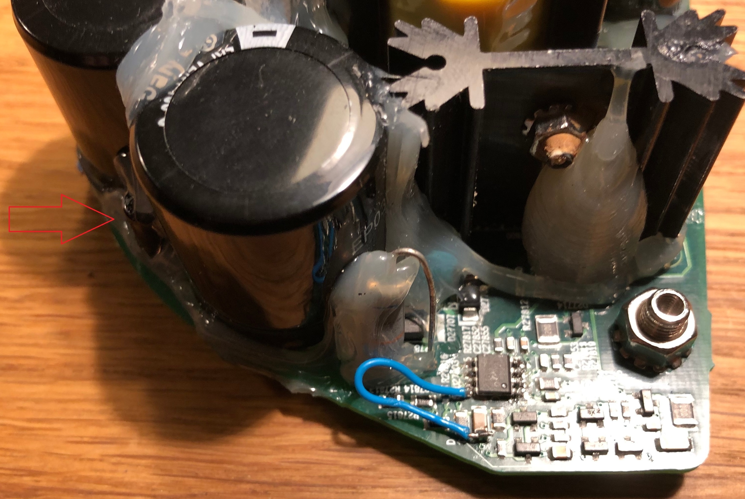
Hello, I happen to have a Gen 1 with similar power issue, I see on your picture you changed the chip.
In my case there is no power on the pin 7 of the small driver IC. I cannot figure out from where it gets the power. I manually power the chip with an external 12 V on that capacitor you solder the blue wire. And the power gets back alive! But it’s not self sustaining and as soon as I remove the external Vcc for the IC it goes back to silence. There must be a component I cannot see on the pcb to supply power to the IC. The small cap 100uF 25V has a connection with the power of the driver IC but I cannot figure-it out. Any ideas? Thanks
- Contributor I
- January 10, 2021
Hello,
My play 5 Gen 1 is acting a bit strange. when i power the speaker up it is working fine. when i restart (unplug an replug) the play 5, to move it for example. it won’t boot up. no lights no sound.
if i wait a couple hours it will boot up again. can this be a capacitor fault or a thermistor somewhere?
I desoldered all the capacitors and measured them, they seem te be okay. (capacity measurement only, no ESR)
my voltages are similar to Anders J. Instead of 0V i get between 0-2 volts which should be 11-12 and 24V. so i think the problem should be somewhere on the HV side.
Since the speaker wont turn on for a while could this mean the capacitors have to be empty first?
(picture from Anders J.)
Hello, I believe we have similar related fail mode, the intermittent start up is related with the Vcc absence on pin 7 of the ICE2QS02 driver chip. It comes from somewhere I cannot see on the board. Since you have removed all the caps from under the glue, can you check if the small cap 100uf/25V (between the 2 big 400V caps) is connected to any of the high voltage rail? I suspect this small cap is the key to supply power to the driver IC. In my case the 2QS02 chip has no power on pin 7 and obviously it will not work.
If I power the IC externally with 12v then the power is fine. I have to figure out what is the intermittent component related to this failure.
Thanks
- Lyricist I
- January 20, 2021
Hello,
My play 5 Gen 1 is acting a bit strange. when i power the speaker up it is working fine. when i restart (unplug an replug) the play 5, to move it for example. it won’t boot up. no lights no sound.
if i wait a couple hours it will boot up again. can this be a capacitor fault or a thermistor somewhere?
I desoldered all the capacitors and measured them, they seem te be okay. (capacity measurement only, no ESR)
my voltages are similar to Anders J. Instead of 0V i get between 0-2 volts which should be 11-12 and 24V. so i think the problem should be somewhere on the HV side.
Since the speaker wont turn on for a while could this mean the capacitors have to be empty first?
(picture from Anders J.)
Hello, I believe we have similar related fail mode, the intermittent start up is related with the Vcc absence on pin 7 of the ICE2QS02 driver chip. It comes from somewhere I cannot see on the board. Since you have removed all the caps from under the glue, can you check if the small cap 100uf/25V (between the 2 big 400V caps) is connected to any of the high voltage rail? I suspect this small cap is the key to supply power to the driver IC. In my case the 2QS02 chip has no power on pin 7 and obviously it will not work.
If I power the IC externally with 12v then the power is fine. I have to figure out what is the intermittent component related to this failure.
Thanks
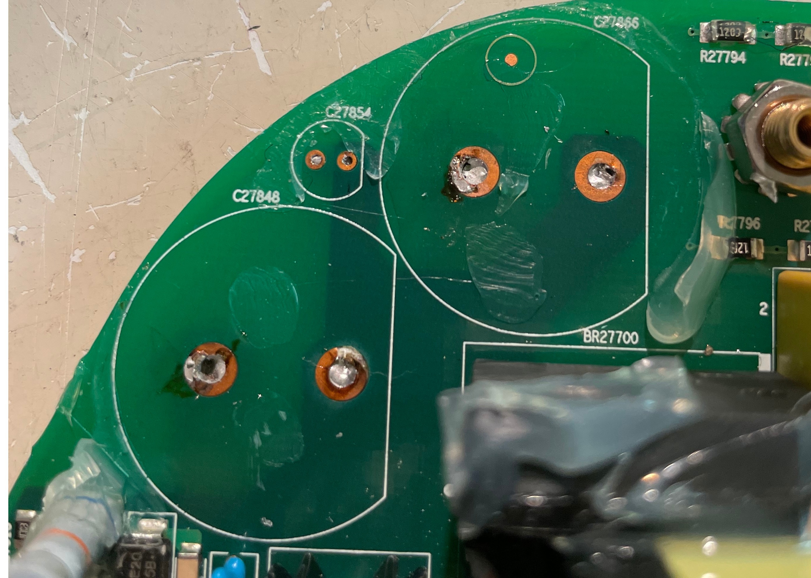
the small cap (C27854) is indeed connected to the high voltage rail. how can it be possible that the cap is providing the power? the other side of the cap goes to a line where some resistors (voltage dividers?) are placed
- Contributor I
- January 21, 2021
Hello, thanks for the picture.
I have-it fixed finally but I do not know the cause. Here it is in words and pictures:
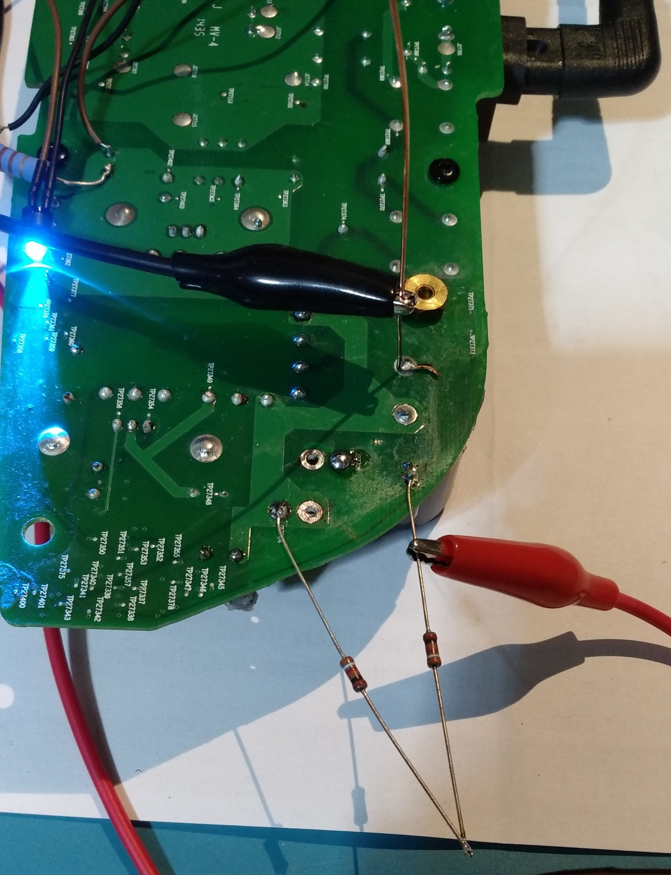
First, small cap (C27854) is not charging from the AC side, those are probably discharge resistors to the remaining capacity in the filtering caps. It’s another mechanism I could not figure out. The C27854 is providing power to the ICE2QS02 driver chip. It goes thru all those small diodes and caps on the edge of the board. The normal behavior on the voltage for C27854 is that is charging up to around 20V slowly and then ( some of those diodes and transistors do that) turns on the power on the ICE2QS02.
Once the chip is starting the voltage is self sustaining to around 13 V, I do not understand from where, maybe from the fly back transformer winding itself.
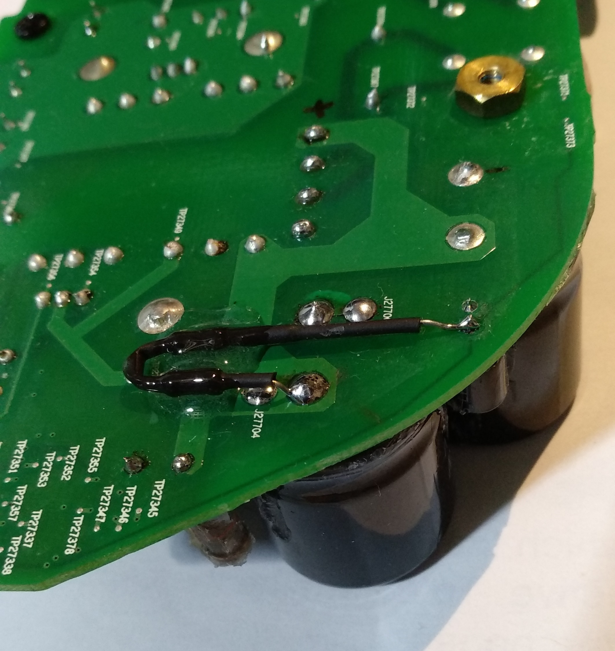
So for me the challenge was to produce the charging of the C27854 up to 20 to start up the IC. I did this by putting 2 390Kohm from the + on the big caps. I monitor the voltage and it’s ramping up slow, like a second or two. After it reaches 20V the IC starts and it self sustain to 13V. It’s 3 days already and still works! meaning there is no other fail. There was no problem in the fuse or rectifier, nothing burned. As you can see the LED turns on with the 2 resistors soldered. This is the story of this fix.
- Prominent Collaborator I
- February 6, 2021
Here is the best I’ve found on debugging Sonos Play:5 hardware issues:
https://sites.google.com/site/sonosdebug/power-topology
The author includes reverse-engineered information about jtag, serial port, connector, and the power supply (including a very helpful partial circuit diagram)!
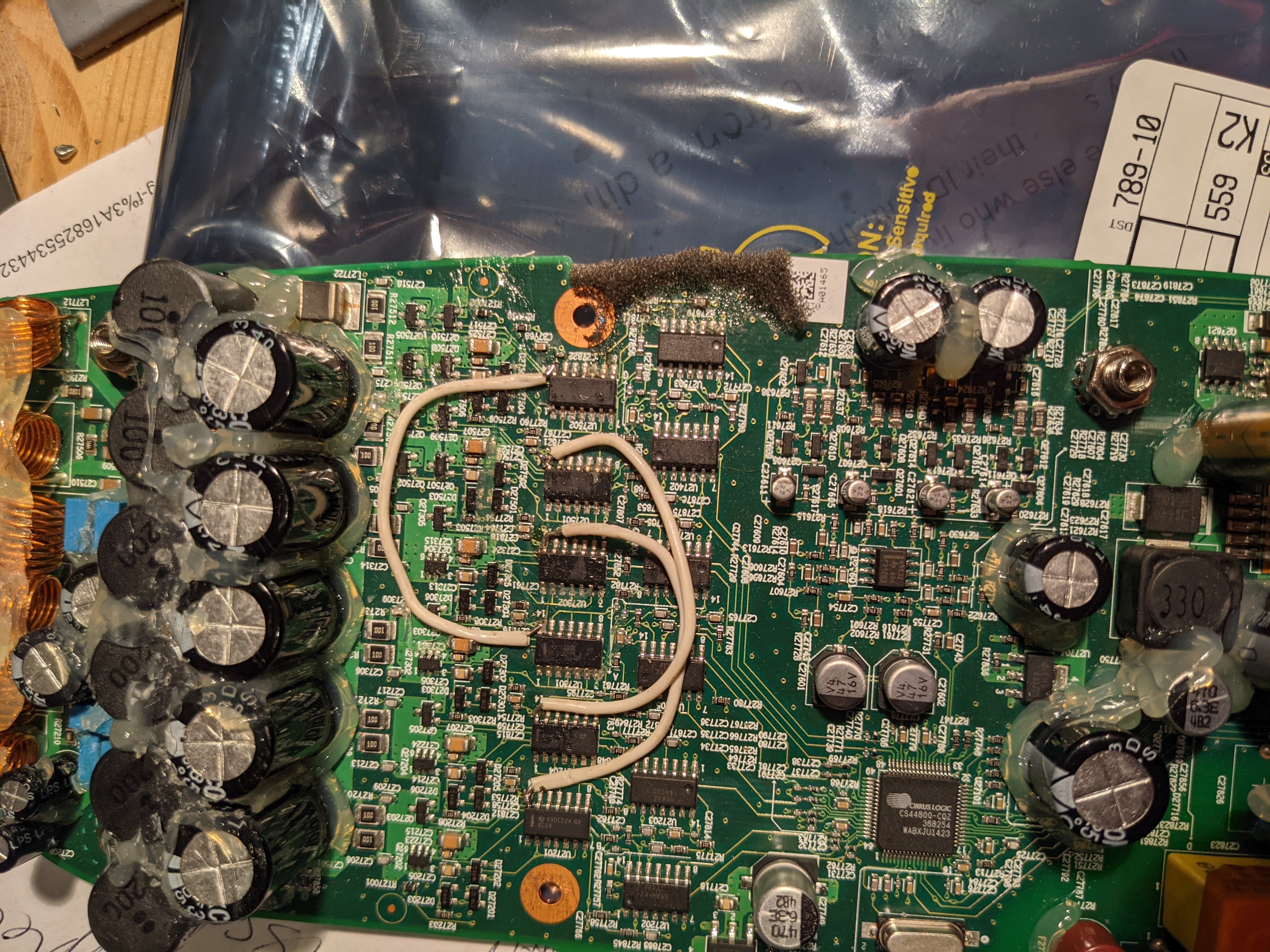
There is nothing about the actual power amp. I have seen a few of these go bad and had only marginal success fixing them. One finding I did have was that a unit with missing bass had some of the driver ICs not having power. It turned out that some of the internal traces had burned out between the driver chips. I jumpered all of the power pins of the 6 ICs together (and all of the grounds too, for good measure), and it solved the problem.
If you have NO sound from the amplifier, then check the biases identified on the schematic and make sure that all of them (12v, 3.3V, 11.1V, 5V) are working.
Hi Tim,
Is your play 5 having issue of very soft volume? Then you jumpered the traces and that fixed it?
Hi. Sorry for the late response. I was locked out… Can't log in
The problem that I had was that of the 5 speakers, some were working and others were not. I found that some of the driver chips did not have power and was able to add power to them… after which it all worked again. Here is a picture of what I jumpered. I think that this was not the complete job… but you should get the idea from here.
- Prominent Collaborator I
- February 6, 2021
Hello, thanks for the picture.
I have-it fixed finally but I do not know the cause. Here it is in words and pictures:
First, small cap (C27854) is not charging from the AC side, those are probably discharge resistors to the remaining capacity in the filtering caps. It’s another mechanism I could not figure out. The C27854 is providing power to the ICE2QS02 driver chip. It goes thru all those small diodes and caps on the edge of the board. The normal behavior on the voltage for C27854 is that is charging up to around 20V slowly and then ( some of those diodes and transistors do that) turns on the power on the ICE2QS02.
Once the chip is starting the voltage is self sustaining to around 13 V, I do not understand from where, maybe from the fly back transformer winding itself.
So for me the challenge was to produce the charging of the C27854 up to 20 to start up the IC. I did this by putting 2 390Kohm from the + on the big caps. I monitor the voltage and it’s ramping up slow, like a second or two. After it reaches 20V the IC starts and it self sustain to 13V. It’s 3 days already and still works! meaning there is no other fail. There was no problem in the fuse or rectifier, nothing burned. As you can see the LED turns on with the 2 resistors soldered. This is the story of this fix.
Well done dvd4me!
The 2QS02G needs some power to start the switching function, but it seems to work quite well with a range of voltages. I think that this is why it was driven with just a simple voltage divider circuit.
You inspired me to dust off an old non-functioning board. Unfortunately I have some other kind of problem. I’ll describe it here, in case someone can help me.
For me the voltage on that pin grows slowly, then falls to 5-10v or so, then starts climbing again and repeating the cycle. Even when I inject 13V to that spot from a bench supply it doesn’t help.
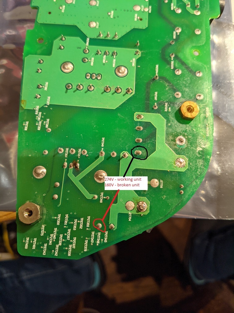
Typical SMPS supplies switches a high voltage via a MOSFET into the primary side of the transformer. That switching is controlled by the 2QS02G. I tried replacing it with no luck, and couldn’t find anything else off around it. What I did find though, was that the high voltage was 160V. I measured it as marked in the attached image. This is a problem for me, since when I measured a known good device, the voltage was 274V. The 160V seems to just be the rectified AC, and is not boosted to 274. I can’t figure out the mechanism that is causing the 274V to be produced, so am stumped. Any ideas?
- Contributor I
- February 7, 2021
Hello, thanks for the picture.
I have-it fixed finally but I do not know the cause. Here it is in words and pictures:
First, small cap (C27854) is not charging from the AC side, those are probably discharge resistors to the remaining capacity in the filtering caps. It’s another mechanism I could not figure out. The C27854 is providing power to the ICE2QS02 driver chip. It goes thru all those small diodes and caps on the edge of the board. The normal behavior on the voltage for C27854 is that is charging up to around 20V slowly and then ( some of those diodes and transistors do that) turns on the power on the ICE2QS02.
Once the chip is starting the voltage is self sustaining to around 13 V, I do not understand from where, maybe from the fly back transformer winding itself.
So for me the challenge was to produce the charging of the C27854 up to 20 to start up the IC. I did this by putting 2 390Kohm from the + on the big caps. I monitor the voltage and it’s ramping up slow, like a second or two. After it reaches 20V the IC starts and it self sustain to 13V. It’s 3 days already and still works! meaning there is no other fail. There was no problem in the fuse or rectifier, nothing burned. As you can see the LED turns on with the 2 resistors soldered. This is the story of this fix.
Well done dvd4me!
The 2QS02G needs some power to start the switching function, but it seems to work quite well with a range of voltages. I think that this is why it was driven with just a simple voltage divider circuit.
You inspired me to dust off an old non-functioning board. Unfortunately I have some other kind of problem. I’ll describe it here, in case someone can help me.
For me the voltage on that pin grows slowly, then falls to 5-10v or so, then starts climbing again and repeating the cycle. Even when I inject 13V to that spot from a bench supply it doesn’t help.
Typical SMPS supplies switches a high voltage via a MOSFET into the primary side of the transformer. That switching is controlled by the 2QS02G. I tried replacing it with no luck, and couldn’t find anything else off around it. What I did find though, was that the high voltage was 160V. I measured it as marked in the attached image. This is a problem for me, since when I measured a known good device, the voltage was 274V. The 160V seems to just be the rectified AC, and is not boosted to 274. I can’t figure out the mechanism that is causing the 274V to be produced, so am stumped. Any ideas?
Hello,
From what I understand now, your board does not start, when the voltage on 2QS02 goes up to 20 and the chip powers on, there must be an error that makes the chip to shut down immediately, thus not self-sustaining to 13V. The power on the caps is simple rectified by the bridge, try to measure on another type of switch power supply. Me I got-it from 110V AC so it goes around that 160V I believe ( I did not wrote down the value. Yours if it is 220VAC so it might be 274 or a bit higher rectified. Maybe your rectifier bridge is broken ( one diode is interrupted, so it’s half of the voltage. This driver chip checks for the voltage, locks for undervoltage. The rectifier is your problem. Check for that.
Regards
- Prominent Collaborator I
- February 8, 2021
For me the voltage on that pin grows slowly, then falls to 5-10v or so, then starts climbing again and repeating the cycle. Even when I inject 13V to that spot from a bench supply it doesn’t help.
Typical SMPS supplies switches a high voltage via a MOSFET into the primary side of the transformer. That switching is controlled by the 2QS02G. I tried replacing it with no luck, and couldn’t find anything else off around it. What I did find though, was that the high voltage was 160V. I measured it as marked in the attached image. This is a problem for me, since when I measured a known good device, the voltage was 274V. The 160V seems to just be the rectified AC, and is not boosted to 274. I can’t figure out the mechanism that is causing the 274V to be produced, so am stumped. Any ideas?
Hello,
From what I understand now, your board does not start, when the voltage on 2QS02 goes up to 20 and the chip powers on, there must be an error that makes the chip to shut down immediately, thus not self-sustaining to 13V. The power on the caps is simple rectified by the bridge, try to measure on another type of switch power supply. Me I got-it from 110V AC so it goes around that 160V I believe ( I did not wrote down the value. Yours if it is 220VAC so it might be 274 or a bit higher rectified. Maybe your rectifier bridge is broken ( one diode is interrupted, so it’s half of the voltage. This driver chip checks for the voltage, locks for undervoltage. The rectifier is your problem. Check for that.
Regards
I don't think that’s right. My input is 113V, and the rectifier is producing 160V (as expected … ie: 113*1.414). If I had 220V, then I would expect to see 320V coming from the rectifier.
The 274V that I measured was from a working unit… not the one that doesn’t work. It could be that when the system is oscillating properly, my meter is getting a bad reading due to the high frequencies present and some kind of induced voltage into the supply. SMPS oscillators often oscillate well above 100kz, and perhaps my meter isn’t giving an accurate measurement at this kind of frequency. If my broken board isn’t oscillating, I’m just getting the 60hz rectified output, and hence the 160V.
I just checked for the undervoltage condition. According to the datasheet, there is a resistor divider network. That seems to be set with Rvins1=1.5M, and Rvin2=20k. With the internal Vref of 1.25V, the shutoff voltage would be 95V (1.25*(1520000/20000)). I never see my rectifier output drop below 160V so I don’t think that’s the problem.
I think that my next step may be to check for an overload condition. The output on the low voltage side of the transformer is fed through a dual inductor. I may try to remove that and see if that stabilizes the input.
- Lyricist I
- February 10, 2021
Hi there,
My sonos play 5 power board had some overvoltage and some parts are blown.
I managed to bring it back to life bij mounting a new PCB fuse3.15A and 2 capacitors 47K275V-X2
2 other components are broken and i cant determine what type they where.
Its about TH27700 at the inlet AC current side, i asume this is a NTC or PTC.
Also MOV27700 is broken, this should be a varistor after the first filter coils.
Does anyone know the partnumbers of these 2 components? You would realy help me out.
Thnx a lot!
Enter your E-mail address. We'll send you an e-mail with instructions to reset your password.
Scanning file for viruses.
Sorry, we're still checking this file's contents to make sure it's safe to download. Please try again in a few minutes.
OKThis file cannot be downloaded
Sorry, our virus scanner detected that this file isn't safe to download.
OK


