
Hi
Play:5, manufacturing date sometime around 2009, is completely dead. No light in LED.
Found several cases of this online, but no solutions.
Does anyone have any knowledge about the problem, og better yet, schematics..
I mainly suspect problem in switch mode power supply. Have only done very basic measuring, but I find 220VAC on primary side, no power on secondary side. I think about ordering a mosfet, and/or a diode I suspect, but if I had schematics I could do some more pinpointing..
- Community
- Get help and assistance with your Sonos system
- Speakers
- Dead Play:5 need schematics or tips
Dead Play:5 need schematics or tips
- July 28, 2016
- 208 replies
- 53643 views
This topic has been closed for further comments. You can use the search bar to find a similar topic, or create a new one by clicking Create Topic at the top of the page.
208 replies
- Lyricist I
- July 23, 2022
Hi guys!
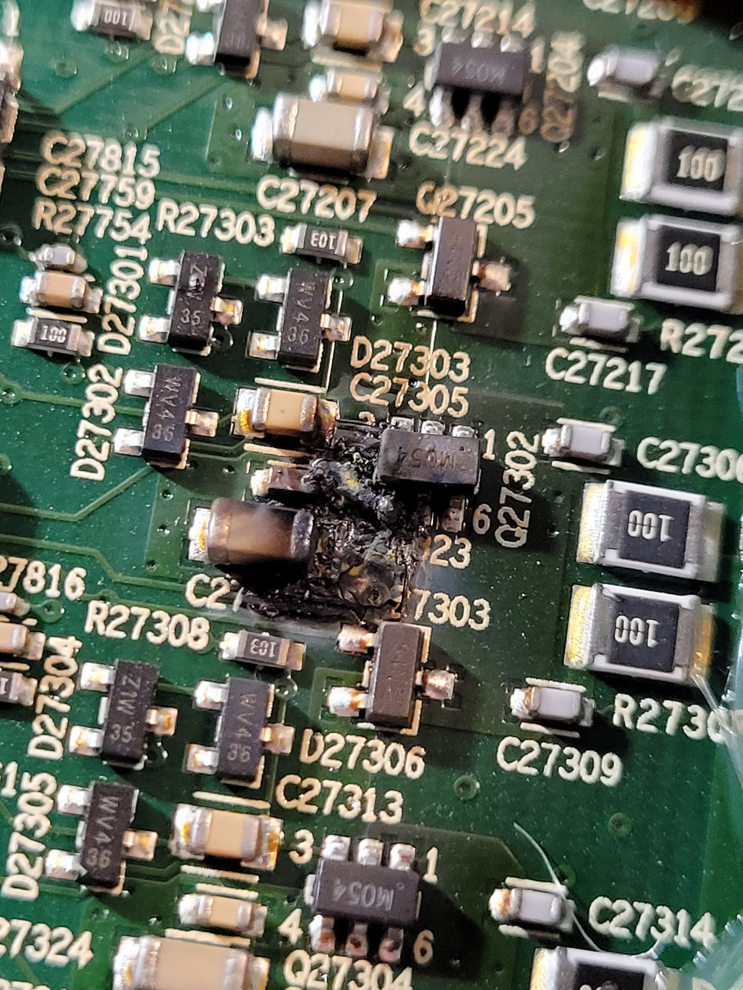
A component called “M054” seems burned at my Play 5 gen 1.
Do I need to replace more than this, I mean did it burn because of some other fault?
Anyone have an idea where to buy a “M054” from?
thanks!
- Contributor I
- July 26, 2022
See Page 6!
Had the same Problem and replaced that part from a spare Board.
After replacing and powering up, an IC burned.
So i didn't continue
- Lyricist I
- July 26, 2022
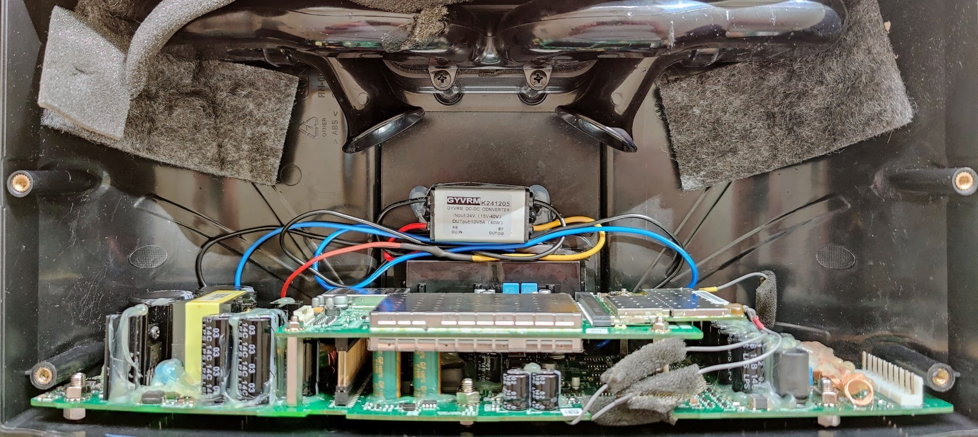
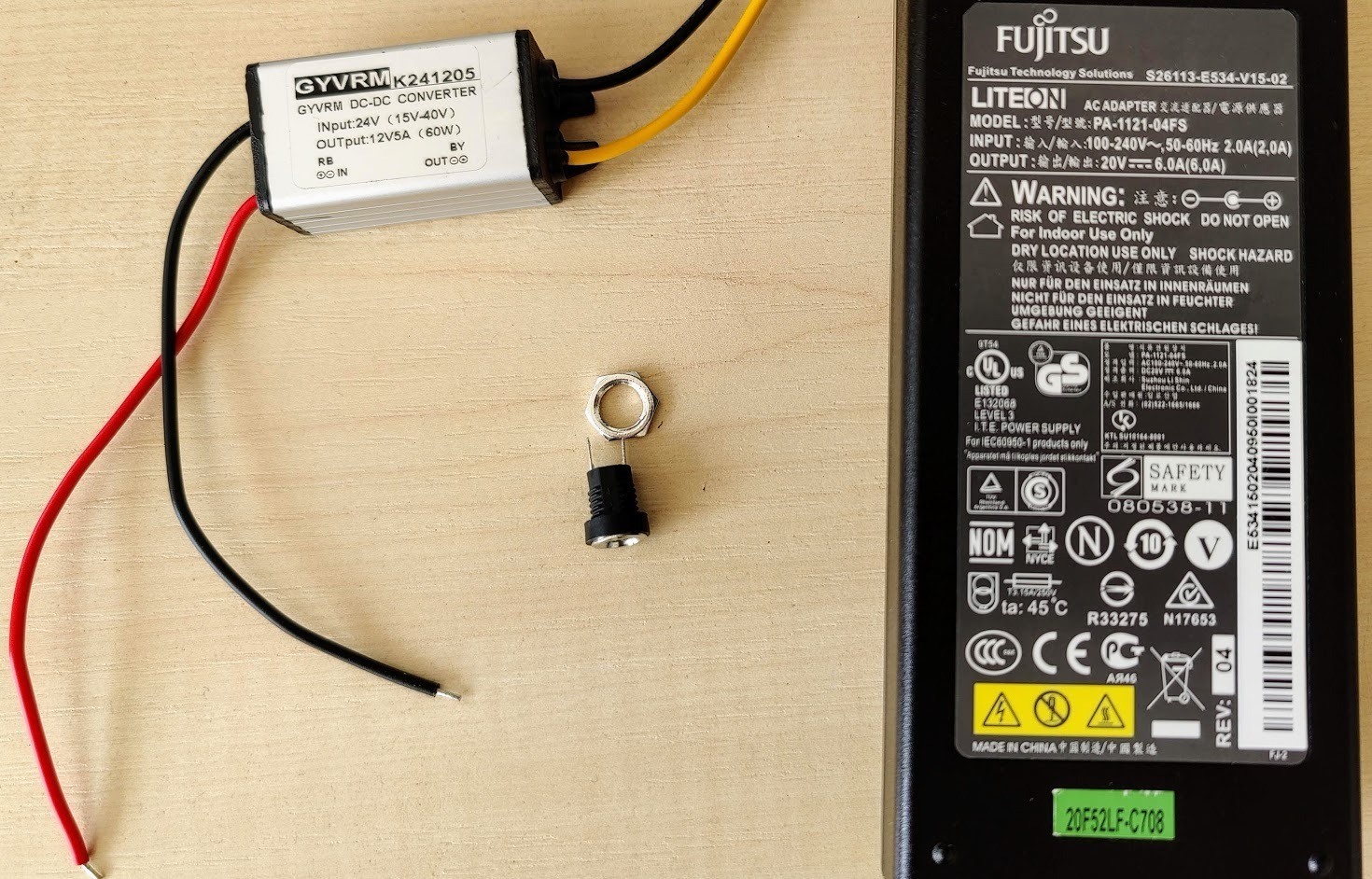
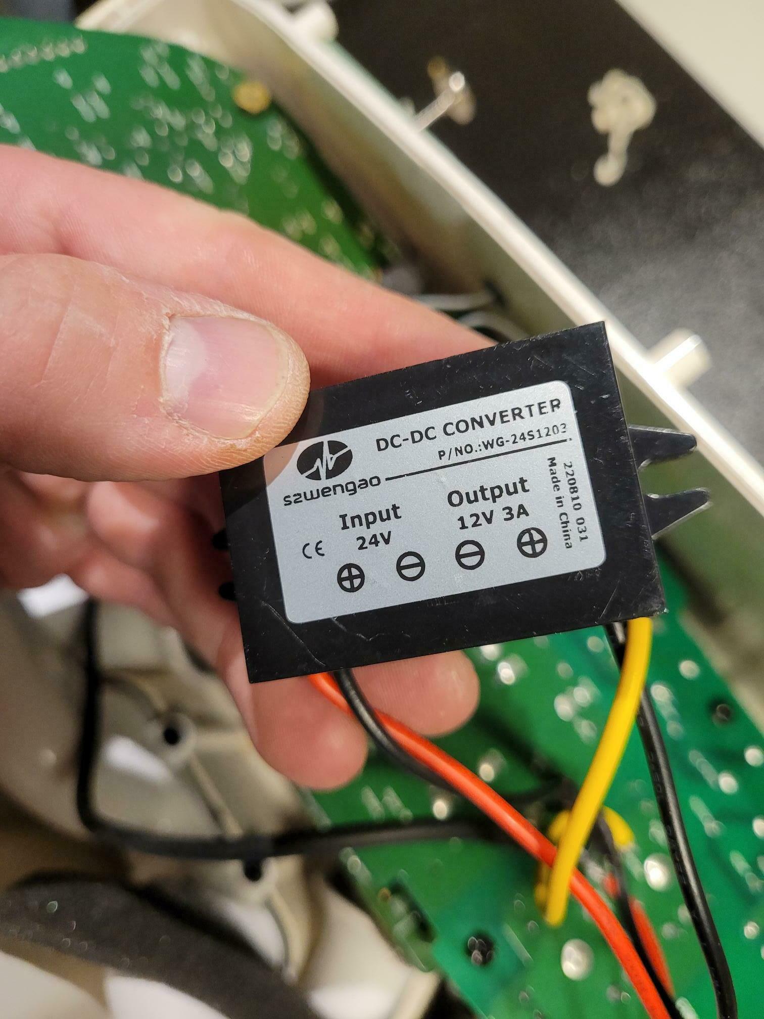
My Play:5 working again. If nothing helps you can power it with an external adapter.
My setup:
- A laptop power adapter (20V - 6A)
- DC-DC converter (24-12V)
- DC connector (female)
The power is enough for max volume and there is no problem.
Thanks for the advice.
You beat me to it by a few hours! Nice job!
I just repaired mine too. I ordered a 24V/4A power supply very cheap on AMazon… $18CAD https://www.amazon.ca/gp/product/B08NYHM4J9/ref=ppx_yo_dt_b_asin_title_o00_s00?ie=UTF8&psc=1 . I chose this one because it was 250 grams, approximately 95 watts, and the size seemed like it would fit -inside- the case.
I had a few DC-DC converters on hand like this: https://www.amazon.ca/gp/product/B07Y88RTXJ/ref=ppx_yo_dt_b_search_asin_title?ie=UTF8&psc=1
I was fortunately able to fit everything inside the case. I piggybacked the 120V supply to the AC-DC supply from the existing socket, and connected my DC-DC converter at the triple inductor like I had suggested a week or so ago. I opened the power supply case, removed the existing wires, and soldered it all in directly. I had to trim the two bass reflex ports about an inch, and was able to position the brick just below those centered between the two mid speakers at the back of the case. I wrapped the PS brick it in a sheet of foam to avoid vibration. It’s a snug fit, but everything went together perfectly. There is no vibration, and I can’t tell the sound difference between this and an unmodified speaker.
Can anyone help clarify if the below diagrams look correct, completely unsure where the -12 V and -24V lines go to,? both to ground?
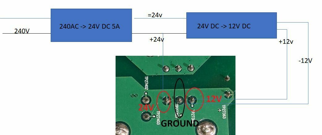
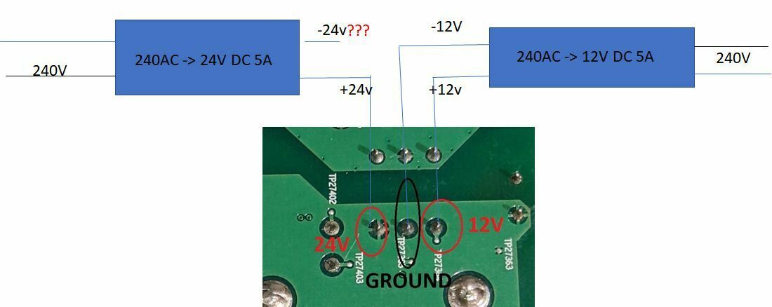
used the upper diagram, its now all systems go, even at full blast it sounds as good as when it was new:).
- Lyricist I
- September 24, 2022
hi guys!
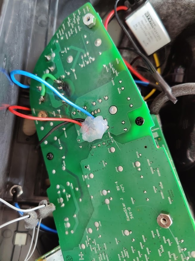
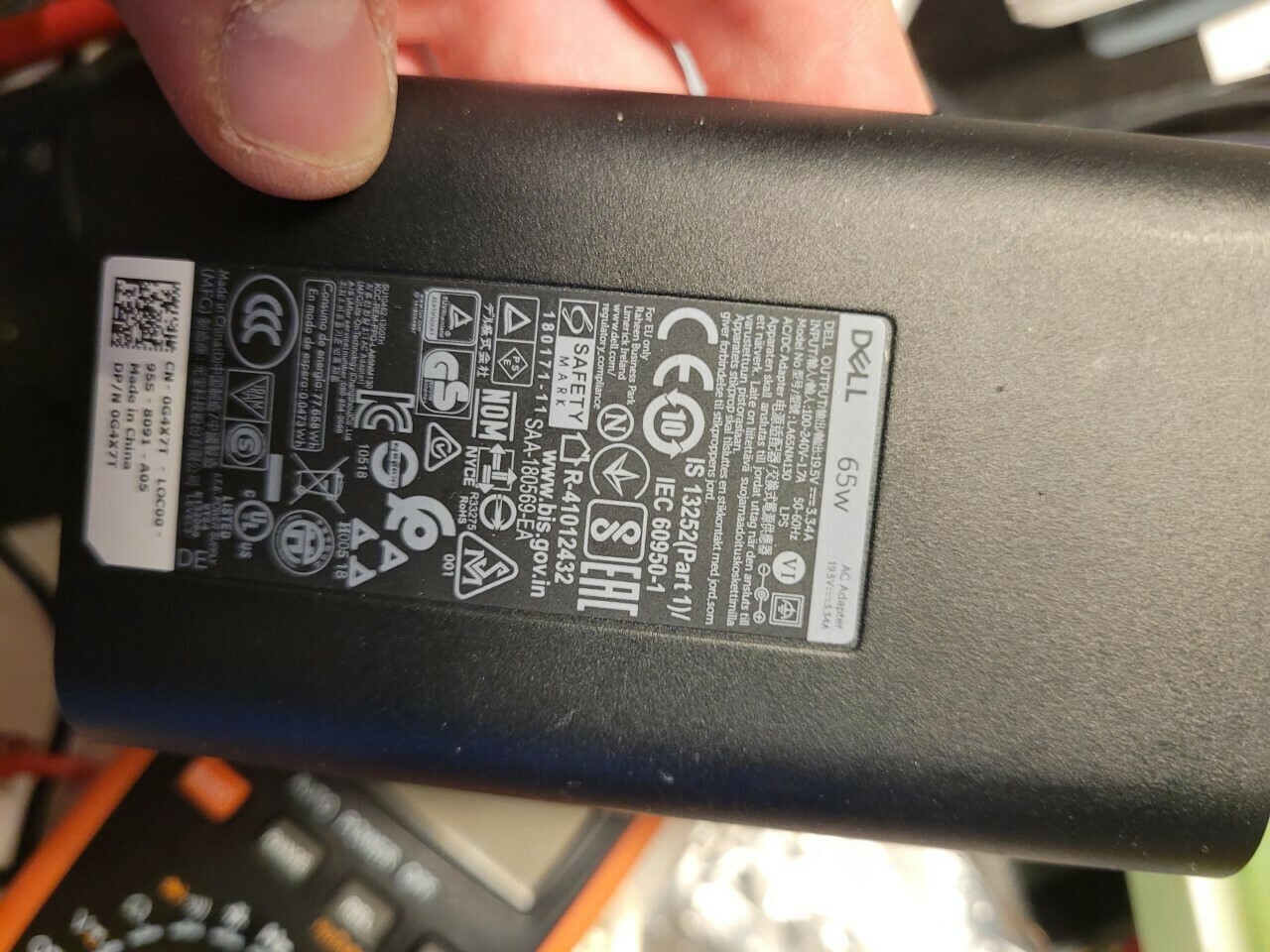
I tried bypassing the powerboard by copying the schematics above. But no success, my Play5 Gen1 won´t start up.
Can you spot anything that I´ve done wrong?
(white is +19V from DELL converter/inverter)
When test-connected, I measure +12V out from yellow cable.
When connected to Sonos board I get 0V from yellow.
- Lyricist III
- October 3, 2022
Hi,
I have a dead Play:5 that I´ve been troubleshooting and came across this thread.
Been measuring all the SMD resistors on the primary side without finding anything wrong.
There is 300VDC on the primary but only about 2VDC on the secondary.
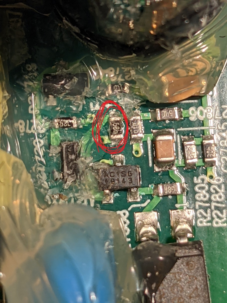
Started to measure the secondary side and found a resistor that was open.
It´s the one marked with red, it´s next to the optocoupler and should be a 68b = 5k resistor.
I have replaced it with a 4.7k 0603 resistor and now I have 26VDC and 12.2VDC on the secondary.
Only wanted to share this as this thread helped me in the right direction.

- Lyricist III
- November 9, 2022
Hi all
im gunna jump on this thread and ask for some from all you fellow fixerupers
my play had a blown fuse and rectifier which i replaced. however its still dead. i have measured around the board but im not 100% what im looking for.
so the big ass caps have 86 volts across them. the ac pind of the rectifier has 90 + volts
is there any test point i should be looking for that anyone knows of?
thanks all in advance
theres also high possibility i have broke somthing replacing that rectifier. is there any test points i can test to between the rectifier and wherever.
thanks again
- Lyricist III
- November 11, 2022
Hi all
im gunna jump on this thread and ask for some from all you fellow fixerupers
my play had a blown fuse and rectifier which i replaced. however its still dead. i have measured around the board but im not 100% what im looking for.
so the big ass caps have 86 volts across them. the ac pind of the rectifier has 90 + volts
is there any test point i should be looking for that anyone knows of?
thanks all in advance
theres also high possibility i have broke somthing replacing that rectifier. is there any test points i can test to between the rectifier and wherever.
thanks again
90V seems a bit low, what are you mains input voltage?
If you are in a 100-115V AC country you should have around 140V DC on the caps.
If you are in a 220-240V AC country, you should have around 300V DC on the caps.
- Lyricist III
- November 12, 2022
hi yer its 240.. .hmmm thats weird. ill have to recheck. i wonder if theres an issue in one of the other layers
- Lyricist III
- November 16, 2022
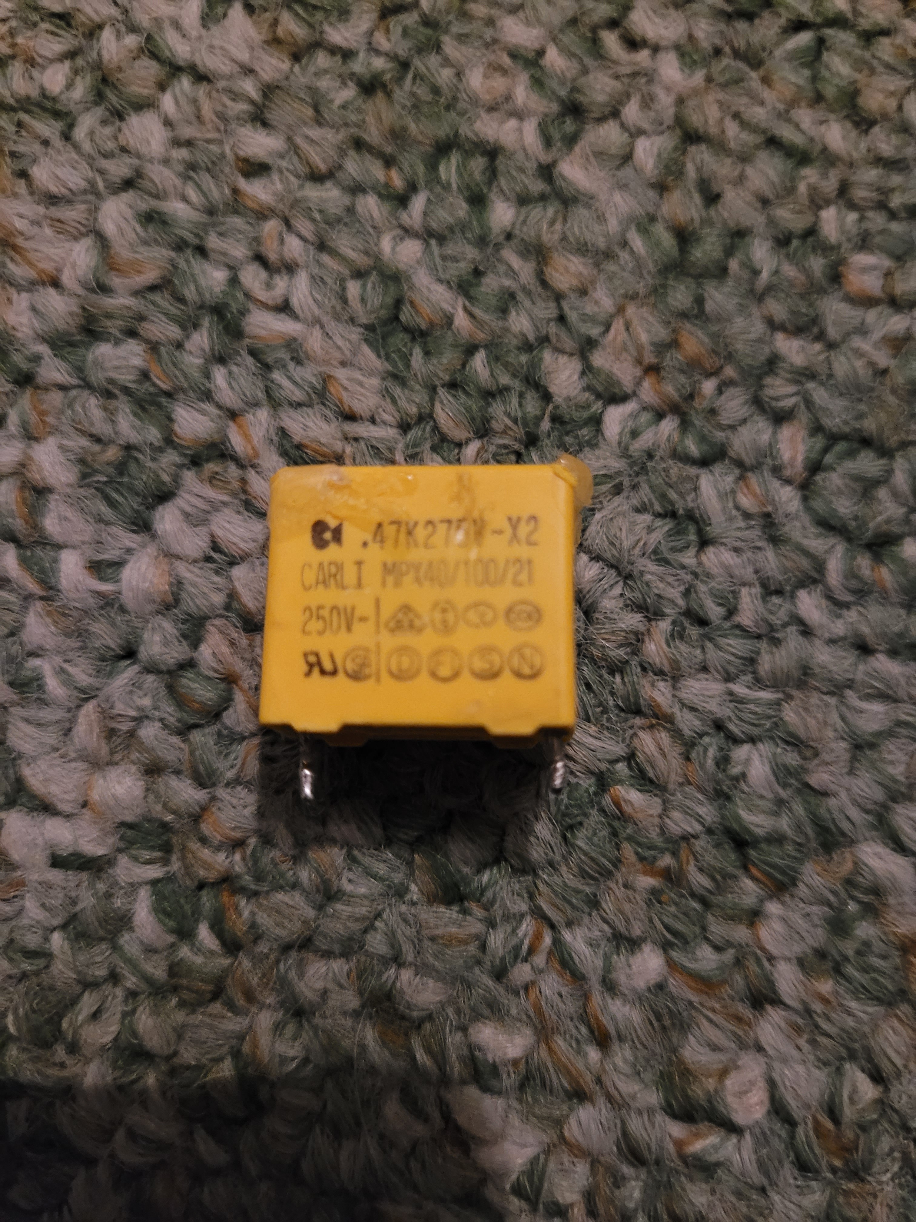
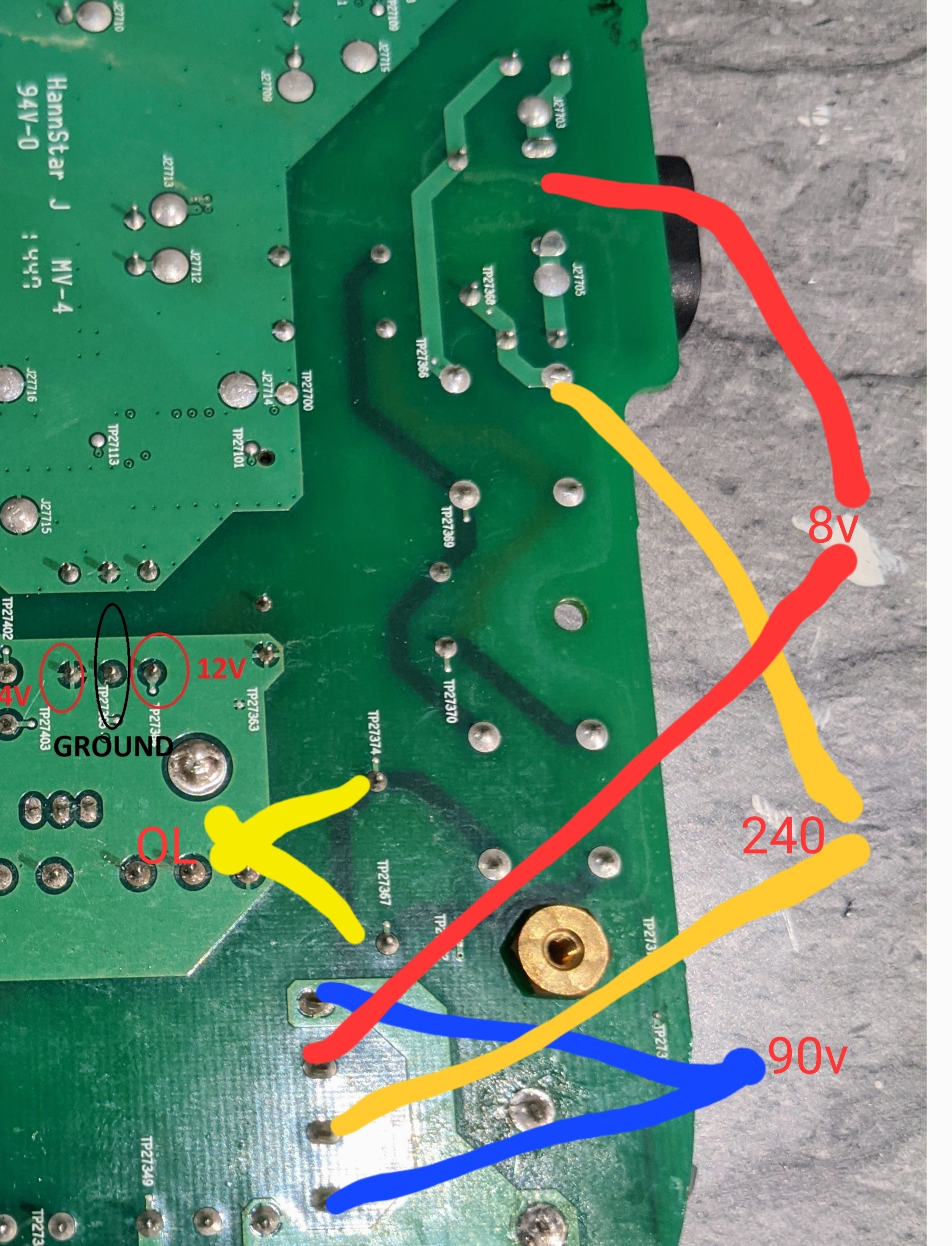
So we get a little further.. on the rectifier i have one ac leg at 240 and the other at 8. And dc output is 90v. So i measure back down the traces that u can see through the board and removed the mpx40 box cap. I get ol testing this. So it looks like when the reciifier blew it took this out and the fuse.i have some coming tomorrow hopefully. Ill report back once tested
- Lyricist III
- November 16, 2022
So we get a little further.. on the rectifier i have one ac leg at 240 and the other at 8. And dc output is 90v. So i measure back down the traces that u can see through the board and removed the mpx40 box cap. I get ol testing this. So it looks like when the reciifier blew it took this out and the fuse.i have some coming tomorrow hopefully. Ill report back once tested
I think that one is more of a suppression capacitor connected between live and neutral.
Isn´t there a inrush current limiting varistor on the opposite side of the fuse at the input socket? Maybe it´s that one that is blown?
- Lyricist III
- November 17, 2022
Yer rhere is thats the next component. But i have pulled this box out and im unabke to vet any reading from it. So im changing this then keep working backwards.
What voltage should i get on botg of those ac pins... across the pair 240 v ac or 2r0v ac on both ?
- Lyricist III
- November 17, 2022
So the plot thickens. I repla ed the box cap with a new one that tests ok.. the old is ol. Howerver i still only get around 100 v dc on the rectifier.
Confused .com
- Lyricist III
- November 19, 2022
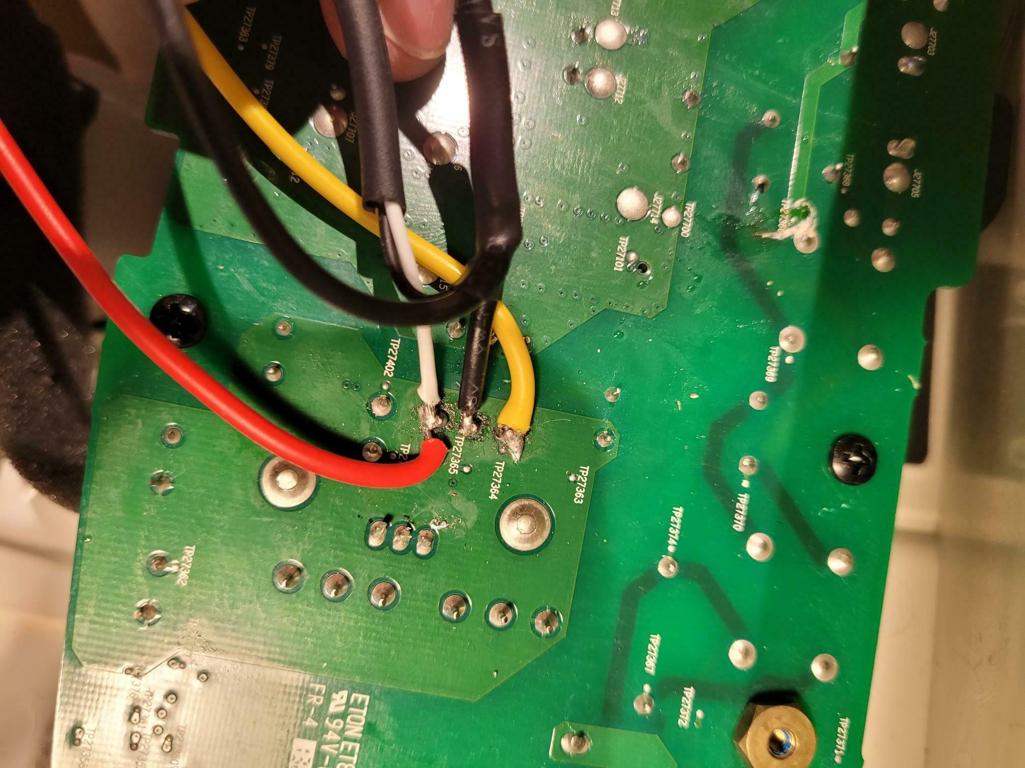
Yay it lives... wired only. It worked out 2 of the traces imside the pcb was damaged tbat bles the fuse cap and rectifier.
So nee problem. Basically the guys who bukld these poxg the sma to the board.. they are no bustdd so im relyinv on some solid core cable as replacement to the positive pin which is still present on all 3
- Lyricist III
- November 19, 2022
Yer rhere is thats the next component. But i have pulled this box out and im unabke to vet any reading from it. So im changing this then keep working backwards.
What voltage should i get on botg of those ac pins... across the pair 240 v ac or 2r0v ac on both ?
So the plot thickens. I repla ed the box cap with a new one that tests ok.. the old is ol. Howerver i still only get around 100 v dc on the rectifier.
Confused .com
You should have the full mains voltage, 240V AC on the rectifiers AC pins.
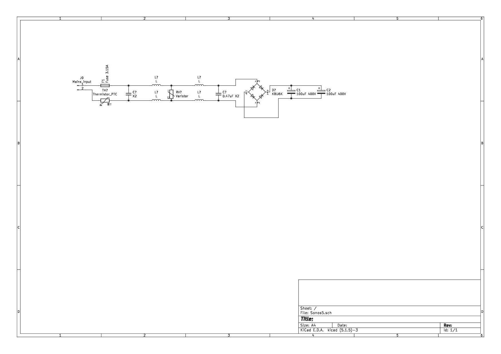
Start at the input jack and measure and see where the voltage disappear.
I did a quick and dirty schematic over the incoming power section,
I don´t have a Play5 with me so I can have missed something
- Lyricist III
- November 19, 2022
Yay it lives... wired only. It worked out 2 of the traces imside the pcb was damaged tbat bles the fuse cap and rectifier.
So nee problem. Basically the guys who bukld these poxg the sma to the board.. they are no bustdd so im relyinv on some solid core cable as replacement to the positive pin which is still present on all 3
That´s good that you find where the problem was.
- Lyricist III
- November 20, 2022
My god. Fat thumbs and small keyboard.. my typing skills need looking at.
Yer so one of the traces to an ac leg on the rectifier was broken also the negative on the dc side of the rectifier to the first cap trace was blown. I wired them direct I also had to replace the fuse rectifier and the box cap.
I have to hard wire it because when i aped the sma cables off the board i busted the connectors because of the glue everywhere. However the centre pin on all 3 board connections are present.. ill have to re solder some wires to them from tbe antennas. Hopefully itll work on wifi/bluetooth then. Thabks all.
That diagram is pretty precise by the way.
- Lyricist I
- December 28, 2022
Hi Folks, First post here :) I’ve been lurking on this thread as I’ve purchased a few used Play 5’s over the last few weeks. Most of them work great, except a couple needed repairs, so I thought I’d pass on what I’ve learned by applying responses from previous posts.
Symptom 1: Low volume from both midrange speakers and distorted bass from woofer.
Solution 1: All of the 820uF caps of the output amps (6 total) were defective (bulging tops and low capacitance measured on all of them). Additionally, the 470uF filter caps on the output stage of the midrange amps we also defective (bulging tops as well). Replaced all 8 caps, midrange and woofer issues resolved.
Symptom 2: Wireless ethernet not working (speaker could not be found after a reset), but wired ethernet works properly. Two Play 5’s exhibiting this fault.
Solution 2: Removed the wireless adapter card from the socket, cleaned the edge connector fingers with flux remover and cleaned the socket pins as well. Reinstalled wireless adapter. Both are now functional with wireless ethernet.
Hope these two fixes helps others with similar issues.
Fooo
- Lyricist I
- January 14, 2023
Hi, all, got a great deal of help from the posts in here so I want to chip in a bit.
My Play 5 1st gen suddenly didn't start up properly. Lamp blinking white. Got the main PCB out and noticed that the the power was cycling every second. This could be measured on many places on the board but for example between pin 7 and 8 on the 2QS02G. There was also a small sound from the transformer at each cycle.
Thanks to page 3 here I could locate that the 10 Ohm resistor R27825 was broken. This resistor was hidden by a big heap of glue. I left it in place since it was broken and soldered a standard resistor over its legs. And the unit now powers on correctly.
A tip: when the speaker front has been removed you can take off the 4 5.5mm nuts of the top PCB and gently lift it up. Now its possible to leave this top board in place and not mess with the wifi antennas and such.
- Lyricist II
- May 17, 2023
Hi All,
I’m trying to revive my Sonos Play 5 Gen1. After coming back from Holiday I plugged in the speaker and got a short circuit for some reason. Both Play 5’s I have are on the same circuit. One of them still working the other dead.
After reading this topic, i opened up the broken one and saw a crack in the SCK-054 en the fuse was blown. After I temporary replaced the fuse the main curcuite got blown again. so started to investigate and bumped on the Bridge Recitifier which is s KBU606 look like there is a short there. Not sure why this failed.
So no I need to replace the KBU606 unfortunately this part is EOL so cannot get the same any reccomendations for a replacement? I Have 2x GBU606 laying but not sure if they will work also the GBU606 is half the thickness of the KBU606.
Also need to replace the SCK-054 which is also EOL looking at ditributors within the region en they don’t seem to have the TKD also so not sure what to replace it with. I normally by from Reichelt in NL.
All the help appreciated as I’m hoping to get it fixed.
Cheers,
Hemant

- Lyricist II
- June 21, 2023
Hi,
So finaly replaced the NTC SCK054 and the KBU606 (took a lager one as this one was not available) Replaced the large Caps 400v with new Phillips and all is back to live again. Except for one issue.
I noticed the left tweeter cracking from time to time randomly. (testes wiith another tweeter same issue).
So replaces the small caps 100uf 25v which are feeding the 2 tweeters (just traced back from the board pin to see which where connected ther are right behin the inductors.
However this did not solve the proble so i’m wondering what is causing the cracking sound on only the left tweeter.
If someone could point me into the right direction?
Hemant
- Lyricist I
- August 6, 2023
SO… My success 2 days ago inspired me to have another look at the two other dead units that I have.
I found a common problem to both of them, and got both working!
I had looked at everything in the high voltage section of the power supply, and couldn’t find any bad components. Despite this, the devices were both not working, and on closer inspection were resetting about once every 5 seconds… There was power ramping up, and just as it hit 20V in the driver power to the IC, it would fall back to 10V or so and start over. This is a problem that others have had on this forum (and in this thread).
I looked at the datasheet for the PWM (ICE2QS02G), and realized that I had not checked the feedback section of the circuit. This is the bit on the ‘other side’ of the opto-isolator. Most of this part of the circuit is buried in glue, but sure enough, when I checked the resistors there, both of my devices had bad resistors in the same spot! The resistor in question is a very small surface mount, with the marking “68b”. Looking in the EIA listings , this is a 4.99k resistor. Both of my devices had open resistors. I added 1/8 watt 4.7k resistors (I didn’t have 5k), and lo and behold both devices now work.
The lower value resistor did have the effect of making the device run at 13V/26V instead of 12V/24V. I don’t see this as a problem, as there are several EH31 regulators on the board, and the only thing (I think) that would be driven directly by these voltages would be the actual audio amplifiers. Those should be tolerant.
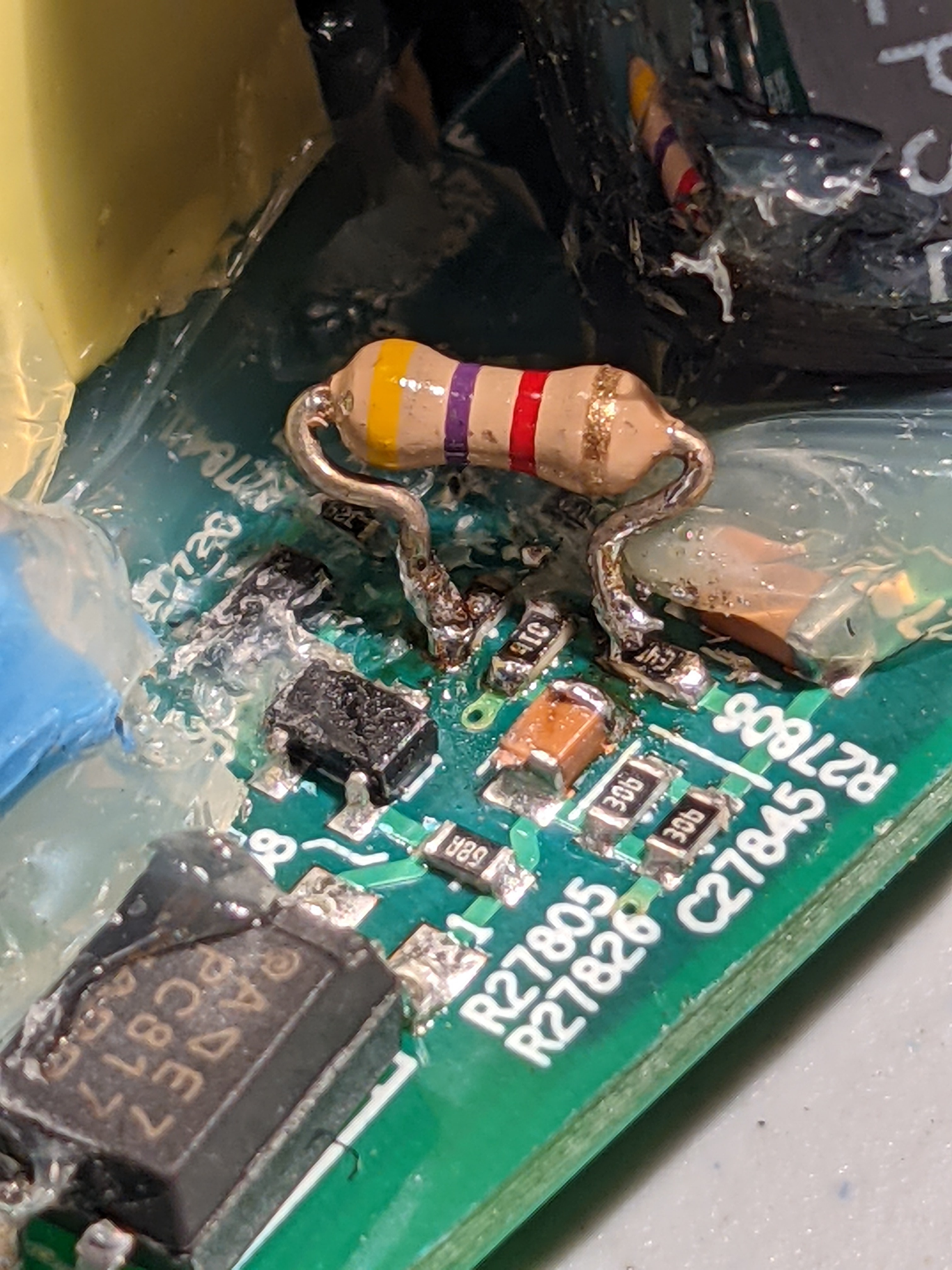
I just got mine to work with the same error, when I measured the resistor on the board it was 40-80k and when I soldered it out it was 4.9k but I replaced it with a new 5.1k and everything worked like new, I suspect a broken solder. Thanks to everyone here!
- Lyricist II
- October 11, 2023
Hello everybody,
I also had a dead play:5 gen 1. Fuse blown and faulty rectifier. I also replaced some caps while the speaker was open:
- the 2 large 400V caps of the power supply. Not sure if they were defective, but without them, it was easier to remove the defective rectifier.
- the 5 35V 820uF caps of the power amp; the heads were bulging.
- the 2 25V 470uF caps that feed the tweeters, they had also bulging heads.
The speaker came alive. So far so good. But the 5 35V 820uF caps are getting really hot. I replaced them again with Panasonic 30mOhm caps, with the same result.
The speaker housing is becoming more hot compared to another play:5 I have.
So I think there must be somewhere a problem that causes my caps to heat and finally damaged them. Or I purchased a wrong type of caps.
Does anyone has an idea?
- Lyricist II
- October 11, 2023
Hi,
So finaly replaced the NTC SCK054 and the KBU606 (took a lager one as this one was not available) Replaced the large Caps 400v with new Phillips and all is back to live again. Except for one issue.
I noticed the left tweeter cracking from time to time randomly. (testes wiith another tweeter same issue).
So replaces the small caps 100uf 25v which are feeding the 2 tweeters (just traced back from the board pin to see which where connected ther are right behin the inductors.
However this did not solve the proble so i’m wondering what is causing the cracking sound on only the left tweeter.
If someone could point me into the right direction?
Hemant
The small caps should be 25V 470uF? Maybe that is the cause?
Enter your E-mail address. We'll send you an e-mail with instructions to reset your password.
Scanning file for viruses.
Sorry, we're still checking this file's contents to make sure it's safe to download. Please try again in a few minutes.
OKThis file cannot be downloaded
Sorry, our virus scanner detected that this file isn't safe to download.
OK