
Hi
Play:5, manufacturing date sometime around 2009, is completely dead. No light in LED.
Found several cases of this online, but no solutions.
Does anyone have any knowledge about the problem, og better yet, schematics..
I mainly suspect problem in switch mode power supply. Have only done very basic measuring, but I find 220VAC on primary side, no power on secondary side. I think about ordering a mosfet, and/or a diode I suspect, but if I had schematics I could do some more pinpointing..
- Community
- Get help and assistance with your Sonos system
- Speakers
- Dead Play:5 need schematics or tips
Dead Play:5 need schematics or tips
- July 28, 2016
- 208 replies
- 57732 views
This topic has been closed for further comments. You can use the search bar to find a similar topic, or create a new one by clicking Create Topic at the top of the page.
208 replies
- Lyricist III
- October 11, 2023
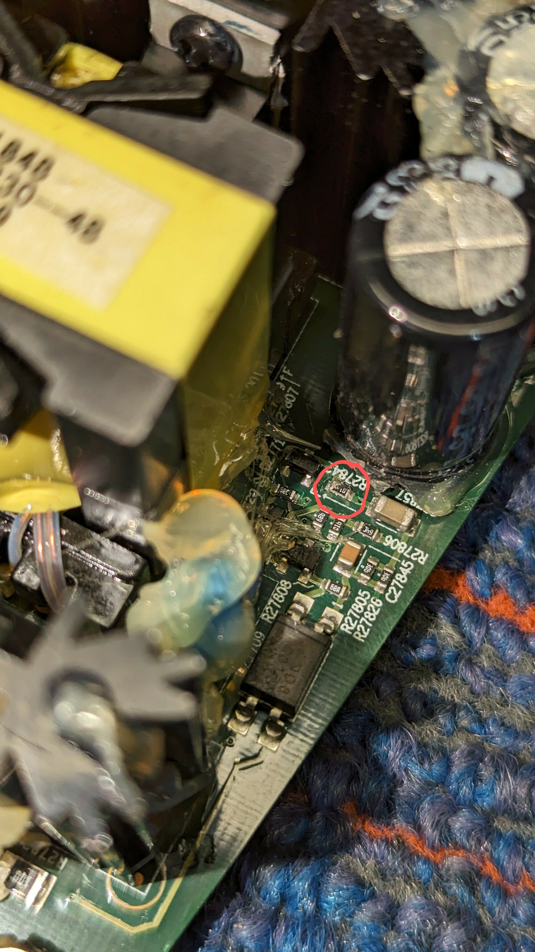
Can someone tell me the value of resistor R27842? Looks like it starts with “01..” but can’t be sure and I definitely can’t make out the last digit. It’s reading open. I think I scraped off some of the markings trying to get the glue off of it.
- Lyricist II
- October 13, 2023
Can someone tell me the value of resistor R27842? Looks like it starts with “01..” but can’t be sure and I definitely can’t make out the last digit. It’s reading open. I think I scraped off some of the markings trying to get the glue off of it.
I've just closed mine after repair... But I will probably receive another one in a few weeks for reparation; I will look for the number and also try to measure it. I hope you can wait that long ...
- Lyricist I
- October 16, 2023
Can someone tell me the value of resistor R27842? Looks like it starts with “01..” but can’t be sure and I definitely can’t make out the last digit. It’s reading open. I think I scraped off some of the markings trying to get the glue off of it.
R27842 - 01b - 1kohm - 1000 ohm
- Lyricist I
- October 23, 2023
SO… My success 2 days ago inspired me to have another look at the two other dead units that I have.
I found a common problem to both of them, and got both working!
I had looked at everything in the high voltage section of the power supply, and couldn’t find any bad components. Despite this, the devices were both not working, and on closer inspection were resetting about once every 5 seconds… There was power ramping up, and just as it hit 20V in the driver power to the IC, it would fall back to 10V or so and start over. This is a problem that others have had on this forum (and in this thread).
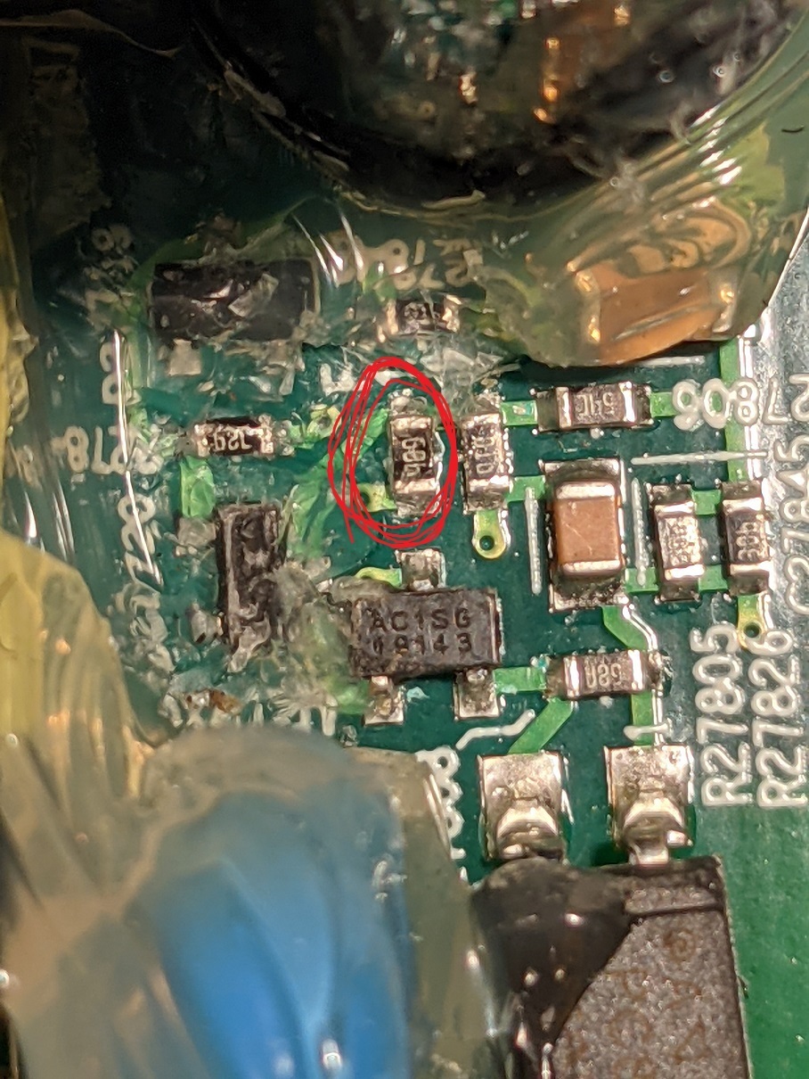
I looked at the datasheet for the PWM (ICE2QS02G), and realized that I had not checked the feedback section of the circuit. This is the bit on the ‘other side’ of the opto-isolator. Most of this part of the circuit is buried in glue, but sure enough, when I checked the resistors there, both of my devices had bad resistors in the same spot! The resistor in question is a very small surface mount, with the marking “68b”. Looking in the EIA listings , this is a 4.99k resistor. Both of my devices had open resistors. I added 1/8 watt 4.7k resistors (I didn’t have 5k), and lo and behold both devices now work.
The lower value resistor did have the effect of making the device run at 13V/26V instead of 12V/24V. I don’t see this as a problem, as there are several EH31 regulators on the board, and the only thing (I think) that would be driven directly by these voltages would be the actual audio amplifiers. Those should be tolerant.
Thank you for your persistence. I had the exact same fault! I don’t think I would have suspected an open resistor in the feedback circuit, such a strange defect. Replaced the resistor together with two ultra cheap bulging „CapXon“ 470uf/35V caps on the secondary side next to the DC/DC converter. Working again like nothing ever happened. Thanks again!

- Contributor I
- October 27, 2023
Hello, first of all sorry for my bad English. I have the following problem, my play 5 gen1 only outputs sound over sub and high. Midrange is dead. I'm already disassembling the play5. You can't see faults with the eye. Which components are responsible for the center? I would be very grateful for tips.
- Lyricist II
- October 29, 2023
Hello, first of all sorry for my bad English. I have the following problem, my play 5 gen1 only outputs sound over sub and high. Midrange is dead. I'm already disassembling the play5. You can't see faults with the eye. Which components are responsible for the center? I would be very grateful for tips.
I would start checking the power amp (where there is a row of 5 capacitors). Top of the cpacitors should be flat. Are you sure yours are not bulged? I had 7 bad caps, the row of 5 and 2 smaller ones next to it.
- Contributor I
- October 29, 2023
Thank you for your reply. I removed the 7 caps today and am waiting for the new ones. I hope it will work again.
- Lyricist III
- November 2, 2023
Can someone tell me the value of resistor R27842? Looks like it starts with “01..” but can’t be sure and I definitely can’t make out the last digit. It’s reading open. I think I scraped off some of the markings trying to get the glue off of it.
R27842 - 01b - 1kohm - 1000 ohm
Thanks VERY much!
- Lyricist III
- November 2, 2023
Can someone tell me the value of resistor R27842? Looks like it starts with “01..” but can’t be sure and I definitely can’t make out the last digit. It’s reading open. I think I scraped off some of the markings trying to get the glue off of it.
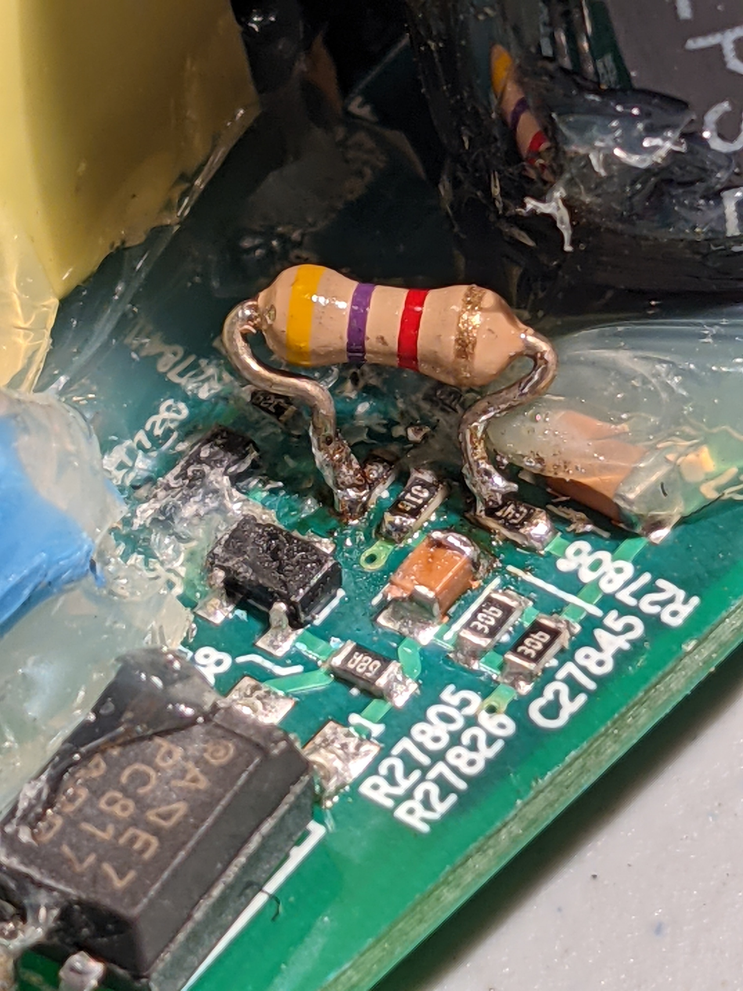
Just wanted to report back with another SUCCESS. My symptom was a slow blinking white light upon power up. This 1k ohm resistor was my problem.
On the bottom side of the board are two points labeled with a TPxxxxx number (are these Test Points?) that are on either side of this resistor, and much easier to access than trying to squeeze into this space with a larger resistor. I removed the dead 1k ohm 0603 SMD resistor from the board and soldered an old carbon film resistor I had laying around from my old college lab days (class of ‘89) across those “test points” on the back side.
Powered up, found my network right away, and it’s back to making music. Thanks to everyone in this thread. All of the posts helped me track this down and fix it.
- Contributor I
- November 4, 2023
Can someone tell me the value of resistor R27842? Looks like it starts with “01..” but can’t be sure and I definitely can’t make out the last digit. It’s reading open. I think I scraped off some of the markings trying to get the glue off of it.
Just wanted to report back with another SUCCESS. My symptom was a slow blinking white light upon power up. This 1k ohm resistor was my problem.
On the bottom side of the board are two points labeled with a TPxxxxx number (are these Test Points?) that are on either side of this resistor, and much easier to access than trying to squeeze into this space with a larger resistor. I removed the dead 1k ohm 0603 SMD resistor from the board and soldered an old carbon film resistor I had laying around from my old college lab days (class of ‘89) across those “test points” on the back side.
Powered up, found my network right away, and it’s back to making music. Thanks to everyone in this thread. All of the posts helped me track this down and fix it.
Can you please show me the points you mean? I have the same problem. Thanks
- Lyricist III
- November 4, 2023
I should have taken a picture before I put it back together. Sorry! But if you flip that board over and post a pic of that area, I can point to what I mean.
If you hold a strong light up to the board you can follow the trace where that resistor is located, and you'll see two points of light shining through on either side of the resistor. Those points have a small solder bump on the back side. That's where I connected my replacement resistor.
This only works if it's that exact resistor that's dead.
- Lyricist III
- November 6, 2023
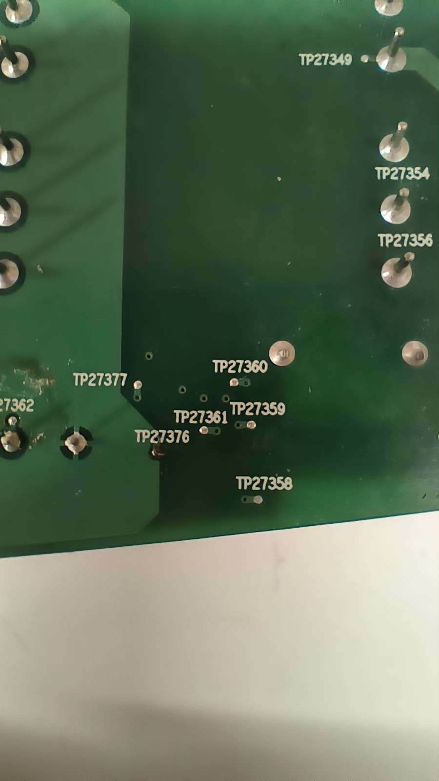
Again, this only works if it's resistor R27842 that's dead. You can verify this by putting your ohmmeter between TP27376 and TP27377. I was seeing an open circuit there. I soldered my new 1,000 ohm resistor between those two points. I left it laying flat against the board to leave plenty of room when putting everything back together.
Good luck!
- Contributor I
- November 8, 2023
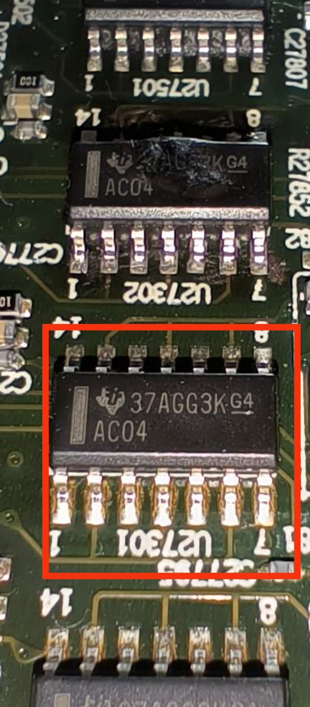
Hi, it's me again. Since my first 2 play 5 are running now I have another problem. Can anyone tell me which component is in the picture? I can't find anything about it on the internet.
- Lyricist III
- November 11, 2023
I just fixed a Sonos play 5 gen 1.
I had to replace the bridge rectifier and fuse.
I also had to replace all except 1 cap on secondary and 2 on primary. First i replaced 8 caps with bulge and tryed the speaker. It started and played but 1 mid and 1 tweeter didnt work.
Started to faultfind and all seemed fine. Then i tested the 2 small output caps (100uF) they were 12pF and 48pF.
I just then decided to take off all secondary electrolytic caps and test them. All bad except one 😛
Works great 👍
Only one problem. I used a 2,5A fuse instead of 3.15A cause i had only 4A next size. Seems to hold for now
Im not sure its worth it in cost but i enjoy fixing stuff 😊
- Lyricist III
- November 16, 2023
Hi, First post here and I’m asking for help with my Play 5 1gen. Bought used and claimed to be working. It powers up fine and connects to WiFi, also streams music fine, so power supply and networking components all working. Problem is both the left and right mids have gone and bass sounds questionable. Now in opening it up it has been worked on before, I can see older style resistors added and think bridge rectifier replaced. There is clear evidence that the main amplifier capacitors have been looked at...probably de-soldered and tested and refitted, this is judging by the flux stains on the back of the board. So I’m assuming speaker failed for power supply issue but when that was fixed the sound issue was discovered, capacitors checked but no solution found.
Now when I visually check board at the amplifier section there is carnage with what looks like multiple failed components. See pics:
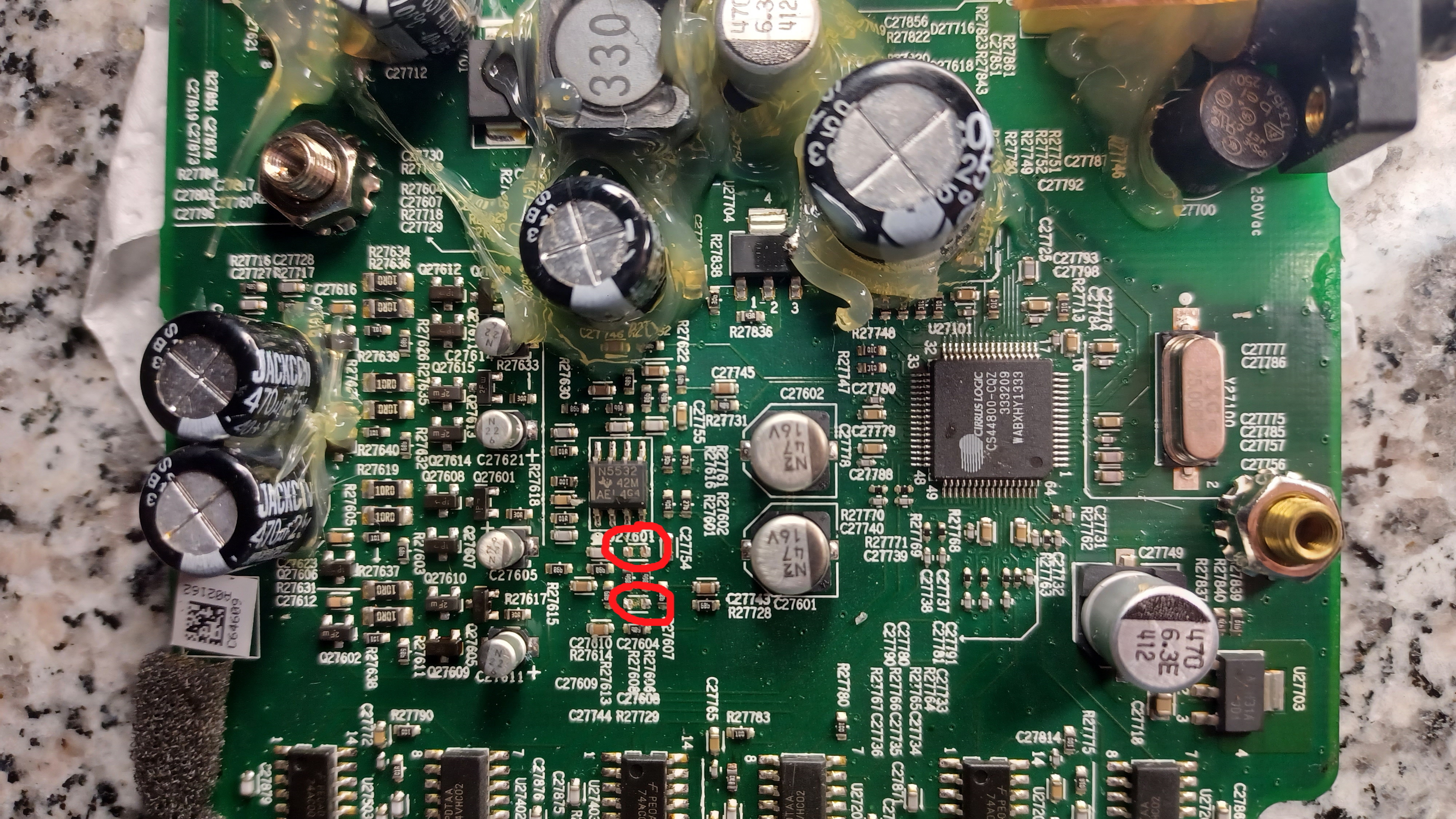
The capacitors C27604 & C27608 were barely attached by one leg and fell off as soon as I touched them, They look OK (tiny) one measures 3.5nF, the other 0.24nF...don’t know if this means good or bad? The fact that they were hanging off must mean they have blown?
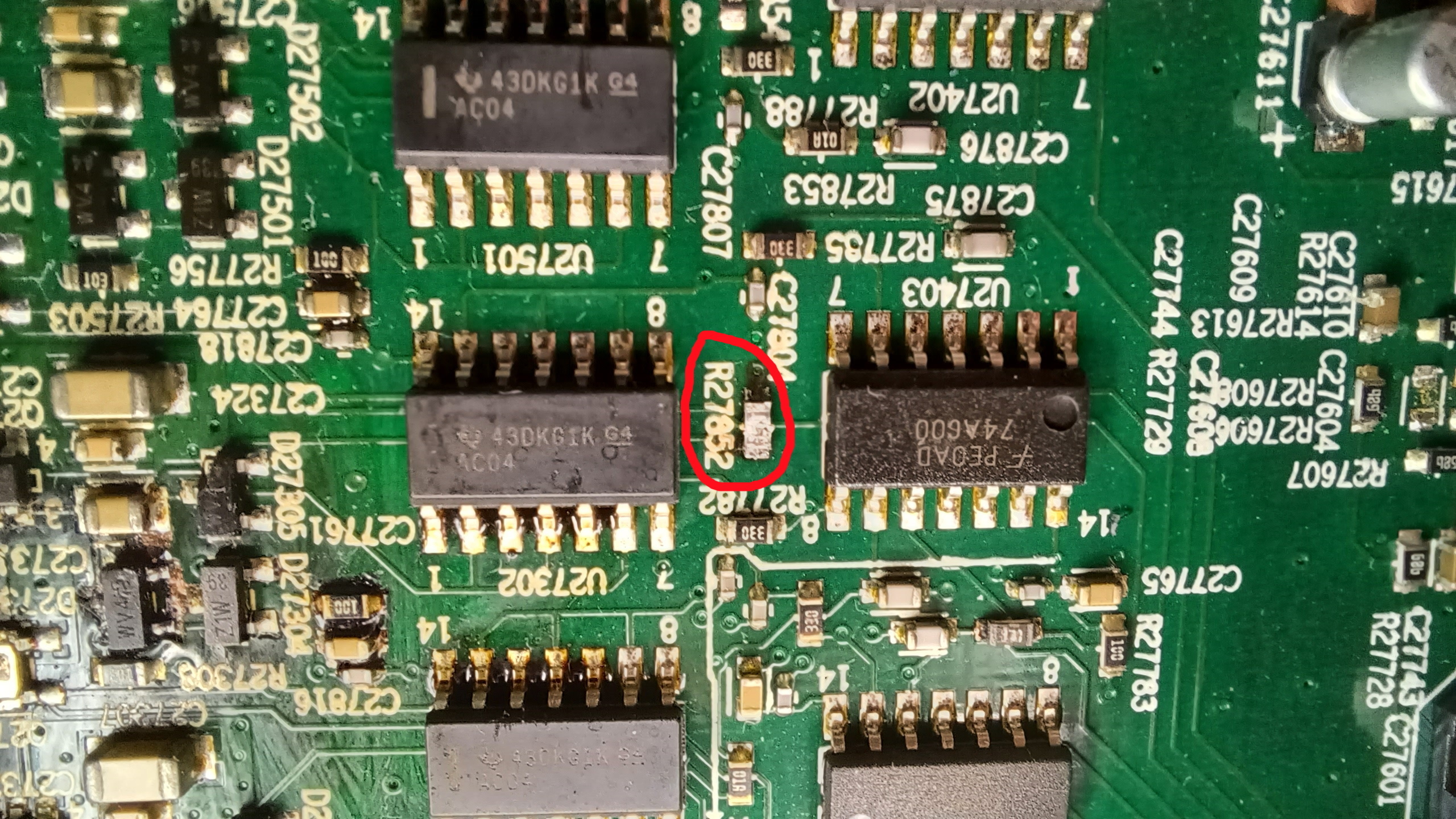
Resistor R27852...looks bad and measures 2.7Mohms
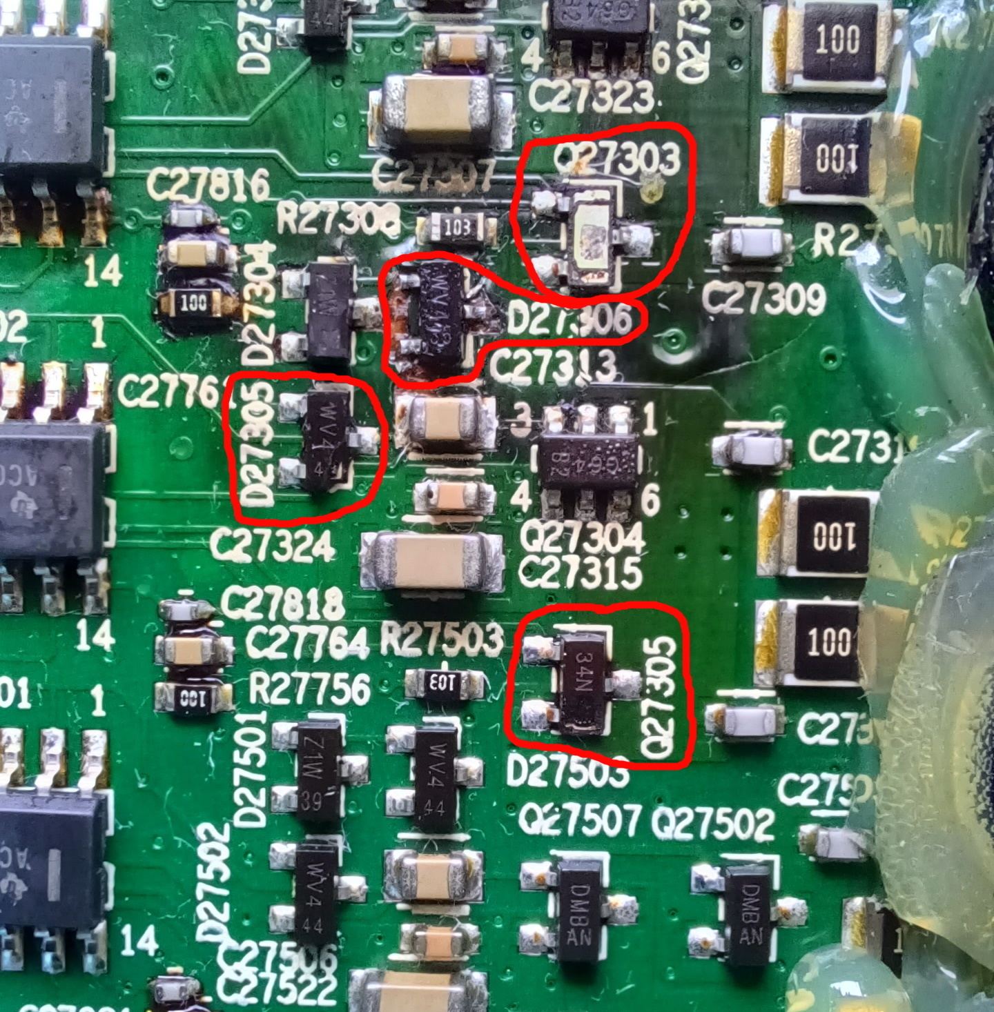
This is the biggy…..Q27303 has exploded, Q27305 and diode D27305 have split casing which I assume means they must have failed? Diode D27306 looks OK but board around it looks a bit cooked?
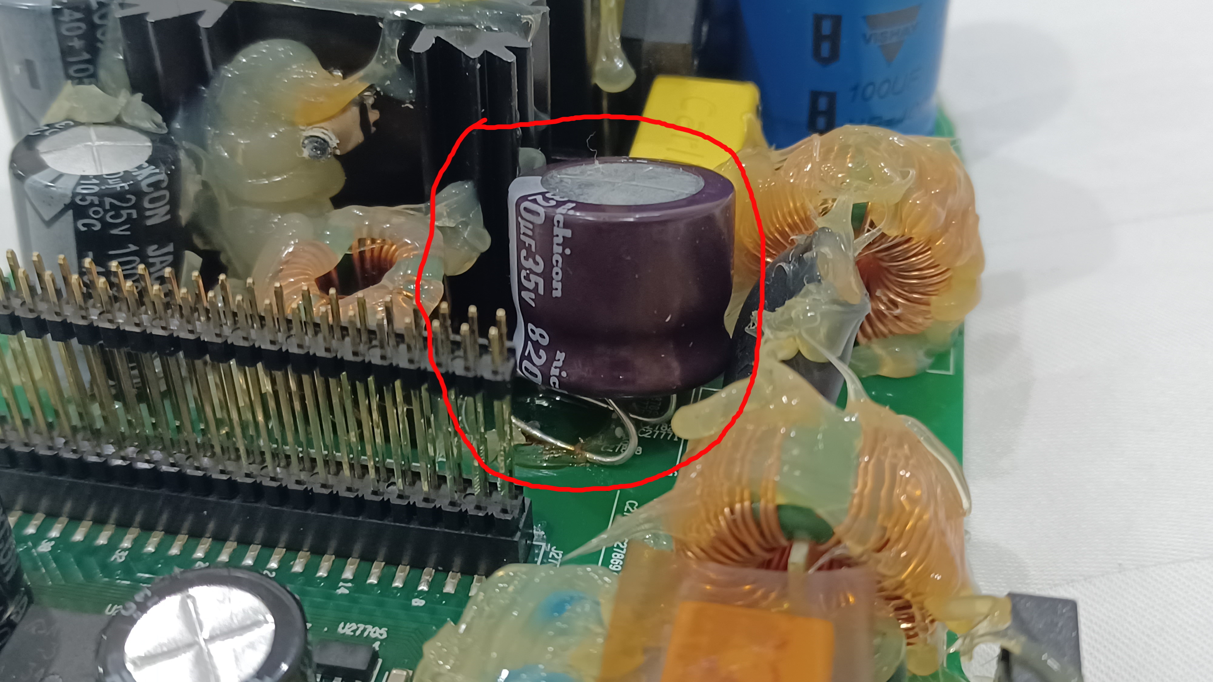
Lastly and this I’m assuming is nothing but this capacitor on the power section of the board is not connected, legs are just bent over and glued to board. Any idea what this is about. Its capacitor C27881.
So question….is it even worth or rather possible attempting to repair? I have no experience of surface mount electronics like this but do have a soldering station so…..happy to give it a go and see it as an interesting project. Bigger issue I’m guessing is identifying component and their availability.
So what do you think guys any and all thoughts gratefully received!
- Lyricist III
- November 16, 2023
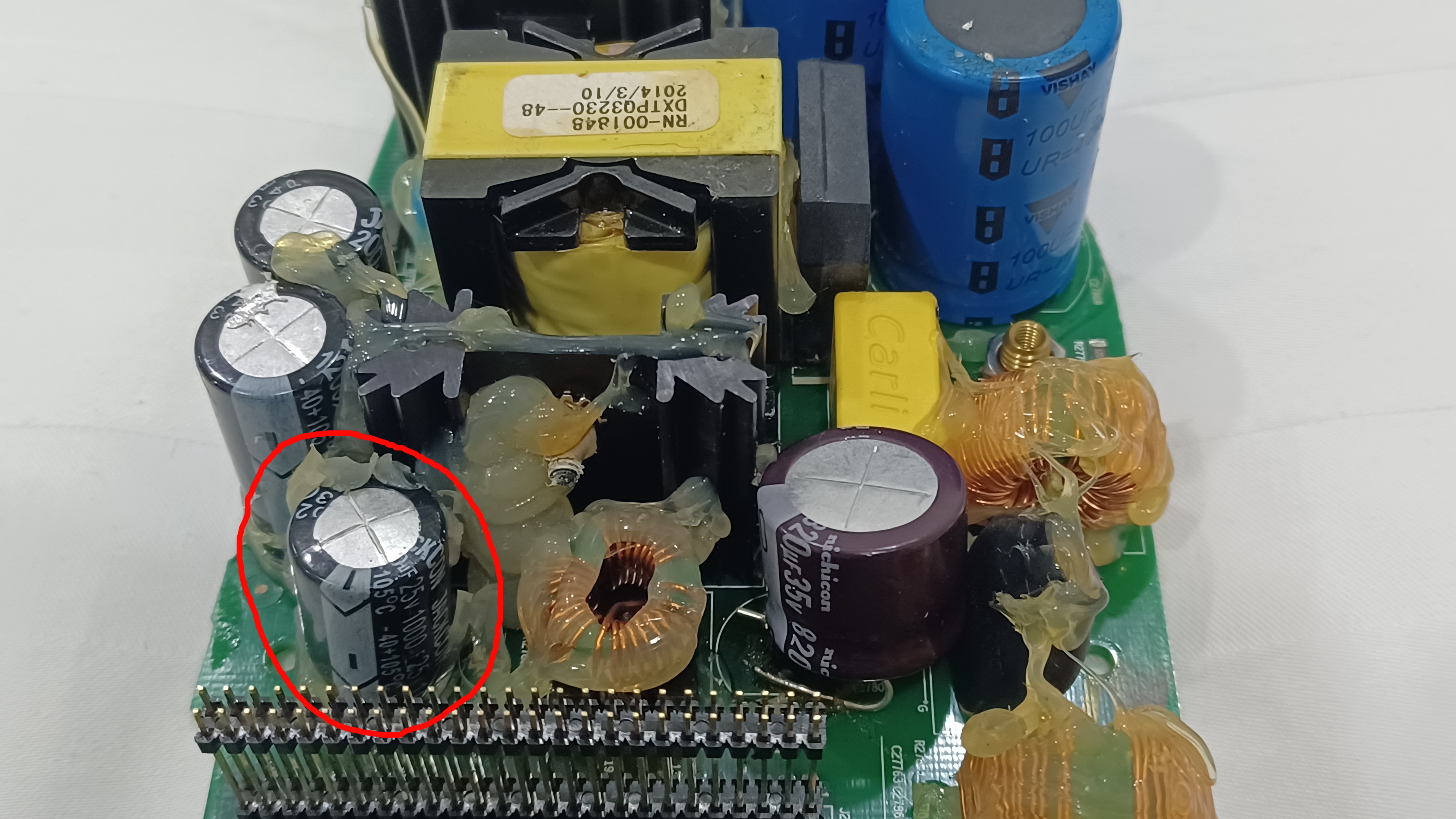
U definitely have capacitor issues. I would fix bad capacitors first and also mount that glued cap properly. The cap next to it have a bulge on top so its bad. Probably more caps.
- Lyricist III
- November 16, 2023
U definitely have capacitor issues. I would fix bad capacitors first and also mount that glued cap properly. The cap next to it have a bulge on top so its bad. Probably more caps.
Thanks for that quick reply Ken. Now that you’ve pointed it out….yes capacitor next door does have a bulging top indeed well noted. I’ve looked in detail at all other big capacitors and that’s the only one with bulging top. That cap was one that has been previously removed and refitted. So that needs replacing but your also saying that the the one with the bent legs glue to board should be properly installed….wonder why anyone would leave it this way?
For clarity this is the cap with bulging top:
- Lyricist III
- November 16, 2023
Yes thats the one thats bad. The other glued on...is it also soldered? Could be that track is broken on the other side of board so they mounted it like that.
- Lyricist III
- November 16, 2023
Seems to be repairable but there is alot of work, skill and correct tools to get it right.
- Lyricist III
- November 16, 2023
Yes thats the one thats bad. The other glued on...is it also soldered? Could be that track is broken on the other side of board so they mounted it like that.
Now that I look at it closely the furthest away leg is soldered on...just but the front leg is not, just glued! It looks...because this capacitor is maybe bigger diameter than the original, they thought it was quick and easy just to bend legs and fit in this way…..clearly very badly! So sorting out these easy to fix capacitors on the power side of the board will give me a bit of practice!
- Lyricist III
- November 16, 2023
Seems to be repairable but there is alot of work, skill and correct tools to get it right.
mmm skill I don’t have...tools I can acquire. From somebody with no experience these tiny capacitors look the most difficult...is there any way I can find out what they actually are?
- Contributor I
- November 16, 2023
For me, both mids and highs were also without function. I replaced all the capacitors, after that no more problems.
Enter your E-mail address. We'll send you an e-mail with instructions to reset your password.
Scanning file for viruses.
Sorry, we're still checking this file's contents to make sure it's safe to download. Please try again in a few minutes.
OKThis file cannot be downloaded
Sorry, our virus scanner detected that this file isn't safe to download.
OK