
The amp has no power. Is there an internal fuse for this unit?
Has anyone taken one apart?
Repair ZP120
- August 3, 2010
- 407 replies
- 46629 views
This topic has been closed for further comments. You can use the search bar to find a similar topic, or create a new one by clicking Create Topic at the top of the page.
407 replies

- Lyricist III
- November 15, 2021
Ok thanks for your fast reply, I indeed looked at the posts before and saw the scheme of all the readings at the pins. I thought I could not test this because when I power on the device it blows up. I will build a dim light tester, check the transformer and the pwm again as well as the diodes. I have a very cheap multimeter with a diode function, is this trustworthy?

- Prominent Collaborator I
- November 21, 2021
Ok thanks for your fast reply, I indeed looked at the posts before and saw the scheme of all the readings at the pins. I thought I could not test this because when I power on the device it blows up. I will build a dim light tester, check the transformer and the pwm again as well as the diodes. I have a very cheap multimeter with a diode function, is this trustworthy?
Yes even a cheap diode tester should work.
- Prominent Collaborator I
- November 25, 2021
readings at the pins. I thought I could not test this because when I power on the device it blows up. I
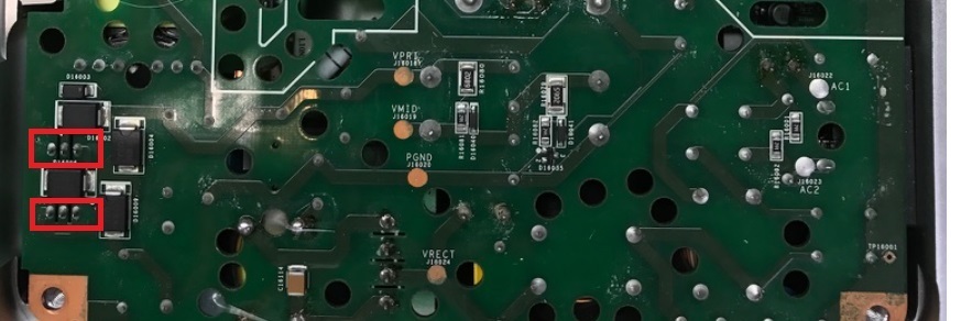
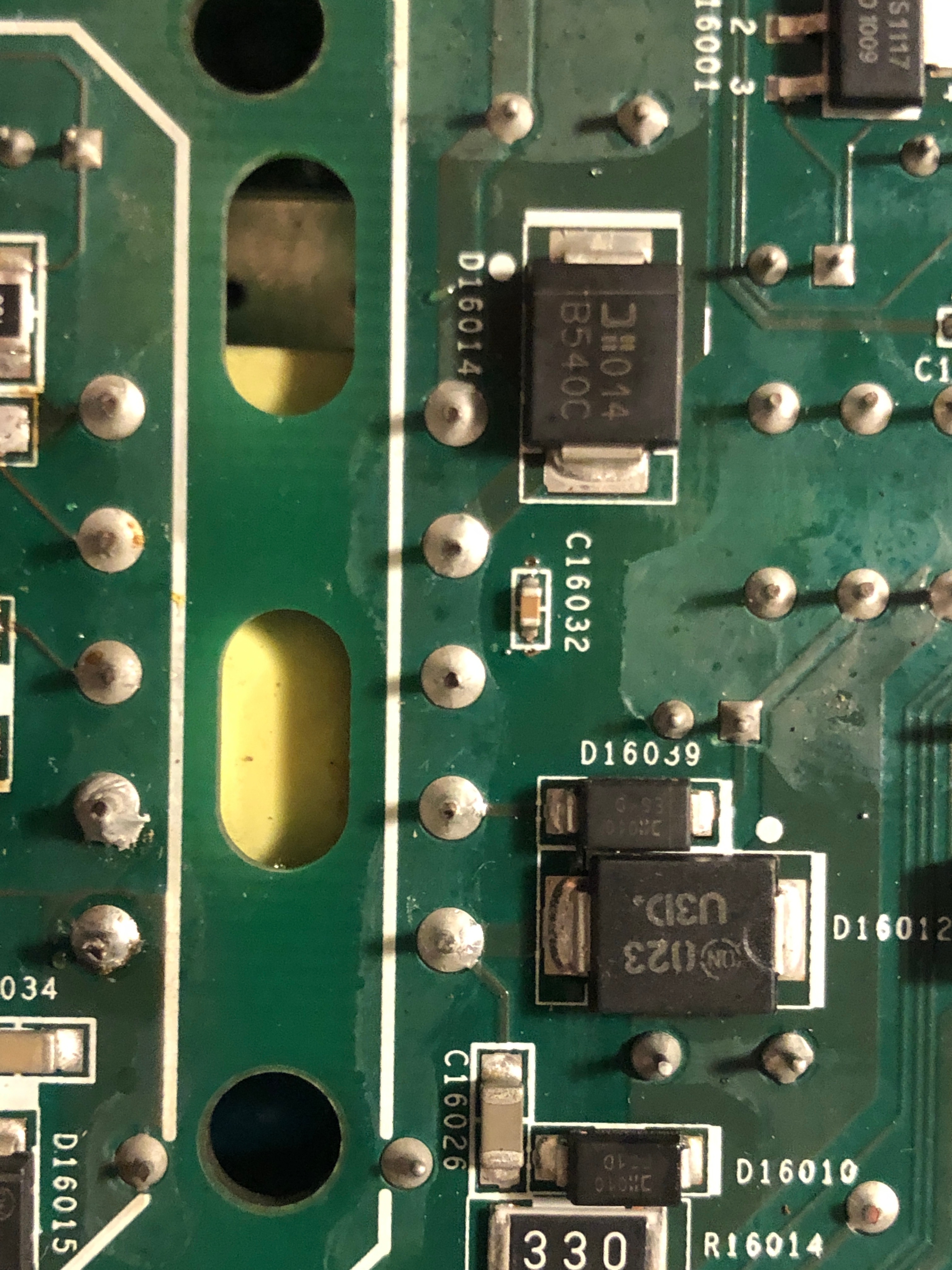
I have an educated guess about what is wrong with your device. If you replaced the PWM and it still doesn’t work, then I’d check the two mosfet devices identified in these images. Look for a short between the various pairs of pins (you should not find any 0V drops if you test the 6 combinations with a diode tester). If you don’t have a diode tester, you can just remove the 2 components and see if the device boots up.
These devices are part of the circuit that is used to generate 36V power that is used to drive the amplifier. It is only active when the device is actually playing music. An otherwise working device will boot up without them, and will even play at very low volume. After booting up without the 36V present, you won’t be able to turn up the volume, and the device will start flashing amber. This isn’t permanent and it will go away once you replace the mosfets.
When the time comes, be aware that the silver clip on the top can be a pain to replace. It can be bent open with two sets of pliers so that it is just a bit narrower than the diodes it covers. That will let it do its job and it will be much easier to replace.
- Prominent Collaborator I
- November 25, 2021
I forgot to attach images to my previous message. Here they are… the mosfets are marked in red boxes.
 +1
+1- Trending Lyricist I
- December 8, 2021
Hello, im from Germany and need your Help.
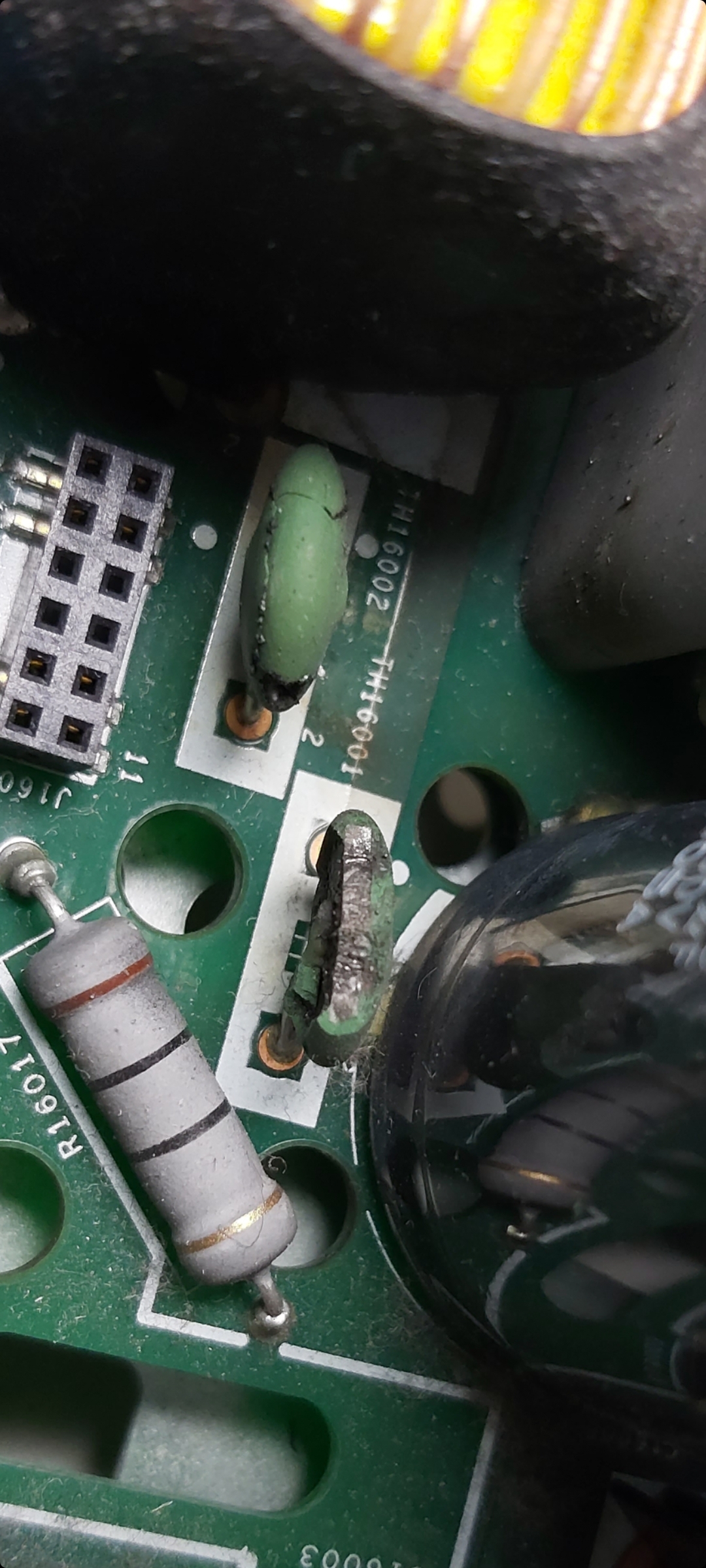
These two capacitors are defective. do you know the data for these?
TH16001 and TH16002.
Thank You
Max
Hi there, are these thermistors the same as they are in an playbar? In my playbar, the green thermistor are burned and I´m looking for the type.
- Prominent Collaborator I
- December 10, 2021
TH16001 and TH16002.
Hi there, are these thermistors the same as they are in an playbar? In my playbar, the green thermistor are burned and I´m looking for the type.
SCK-054 or SCK-083 will work. These limit inrush current, and either of these does that (they have 5 and 8 ohms of initial resistance). The maximum amperage is 4A for the SCK-053, and 3A for SCK-083. Either of these is more than enough current for a playpar.
+1- Trending Lyricist I
- December 10, 2021
Do you mean a SCK-054 or a SCK-053 with 4A? Anwalt,here in germany, I don't find anyone, who sells one of them.
- Prominent Collaborator I
- December 10, 2021
Do you mean a SCK-054 or a SCK-053 with 4A? Anwalt,here in germany, I don't find anyone, who sells one of them.
I meant SCK-083. Here is a datasheet for the series… https://datasheetspdf.com/pdf-file/924750/Microtherm/SCK-054/1. Looks like an SCK-103 will work too.
- Prominent Collaborator I
- December 10, 2021
But sure… if you can find an SCK-053 (another manufacturer perhaps), then that would work. I think you want the first two digits >=5 and the last digit 3 or higher.
+1- Trending Lyricist I
- December 16, 2021
I'm sorry, but I'm going to be stupid trying to find a suitable spare part.Can someone give me a link to a suitable spare part, e.g. at mouser or digikey?Many Thanks
- Lyricist III
- December 18, 2021
readings at the pins. I thought I could not test this because when I power on the device it blows up. I
I have an educated guess about what is wrong with your device. If you replaced the PWM and it still doesn’t work, then I’d check the two mosfet devices identified in these images. Look for a short between the various pairs of pins (you should not find any 0V drops if you test the 6 combinations with a diode tester). If you don’t have a diode tester, you can just remove the 2 components and see if the device boots up.
These devices are part of the circuit that is used to generate 36V power that is used to drive the amplifier. It is only active when the device is actually playing music. An otherwise working device will boot up without them, and will even play at very low volume. After booting up without the 36V present, you won’t be able to turn up the volume, and the device will start flashing amber. This isn’t permanent and it will go away once you replace the mosfets.
When the time comes, be aware that the silver clip on the top can be a pain to replace. It can be bent open with two sets of pliers so that it is just a bit narrower than the diodes it covers. That will let it do its job and it will be much easier to replace.
thanks! I found a short on the mosfet side, but to be sure, I also want to replace the schottky diodes on the other side… Do you have any idea on what replacement part to order for these?
- Prominent Collaborator I
- December 19, 2021
I'm sorry, but I'm going to be stupid trying to find a suitable spare part.Can someone give me a link to a suitable spare part, e.g. at mouser or digikey?Many Thanks
Either of these will work (both are in stock as of now)
Mouser #: 527-RL4504-3.2859S54
Mouser # 954-5D2-10LD
- Prominent Collaborator I
- December 19, 2021
thanks! I found a short on the mosfet side, but to be sure, I also want to replace the schottky diodes on the other side… Do you have any idea on what replacement part to order for these?
If you are referring to the pair of TO220 Schottkys mounted to the case, those are 10 Amp 100 Volt. Part number SBR1010CT
- Lyricist I
- January 5, 2022
Hello, im from Germany and need your Help.
These two capacitors are defective. do you know the data for these?
TH16001 and TH16002.
Thank You
Max
Hi guys, I own a connect amp that was plugged (by previous owner) in to 220v when switch was on 110 v.
I replaced the fuse, replaced the TVR14241 (mov) and i noticed that the TH16001 also cracked. I could not source the Sck054 needed to replace this part in my local electronics store, so I hardwired it for now, and everything works perfectly.
Questions are:
- with normal use (no power surge, no wrong voltage), will the unit get damaged if I keep it like that?
- is th16001 used in 220v setup, or is it for 110v only, and th16002 for 220v?
If it will Increase the lifespan of the unit, i will order the SCk054 online.
Thanks for this super interesting group discussion, got me already quite far!
- Lyricist III
- January 8, 2022
thanks! I found a short on the mosfet side, but to be sure, I also want to replace the schottky diodes on the other side… Do you have any idea on what replacement part to order for these?
If you are referring to the pair of TO220 Schottkys mounted to the case, those are 10 Amp 100 Volt. Part number SBR1010CT
the short I mentioned was not correctly diagnosed. So No short is detected on the mosfet side. Schottky diodes also seemed ok after removing them.
I build a dim light bulb tester, replaced the 10 ohm resistor, and removed the MOSFET’s and schottky diodes. When plugging the device in, the bulb goes full brightness. I am using a 53W bulb. Also plugged it in With the input/network card removed. Lamp still goes on… Owner told me the damage was probably caused by water as the amp was placed under a bathtub… Any thoughs? Not sure If the PWM is still ok But as I replaced it last month, it should be.
- Lyricist III
- January 8, 2022
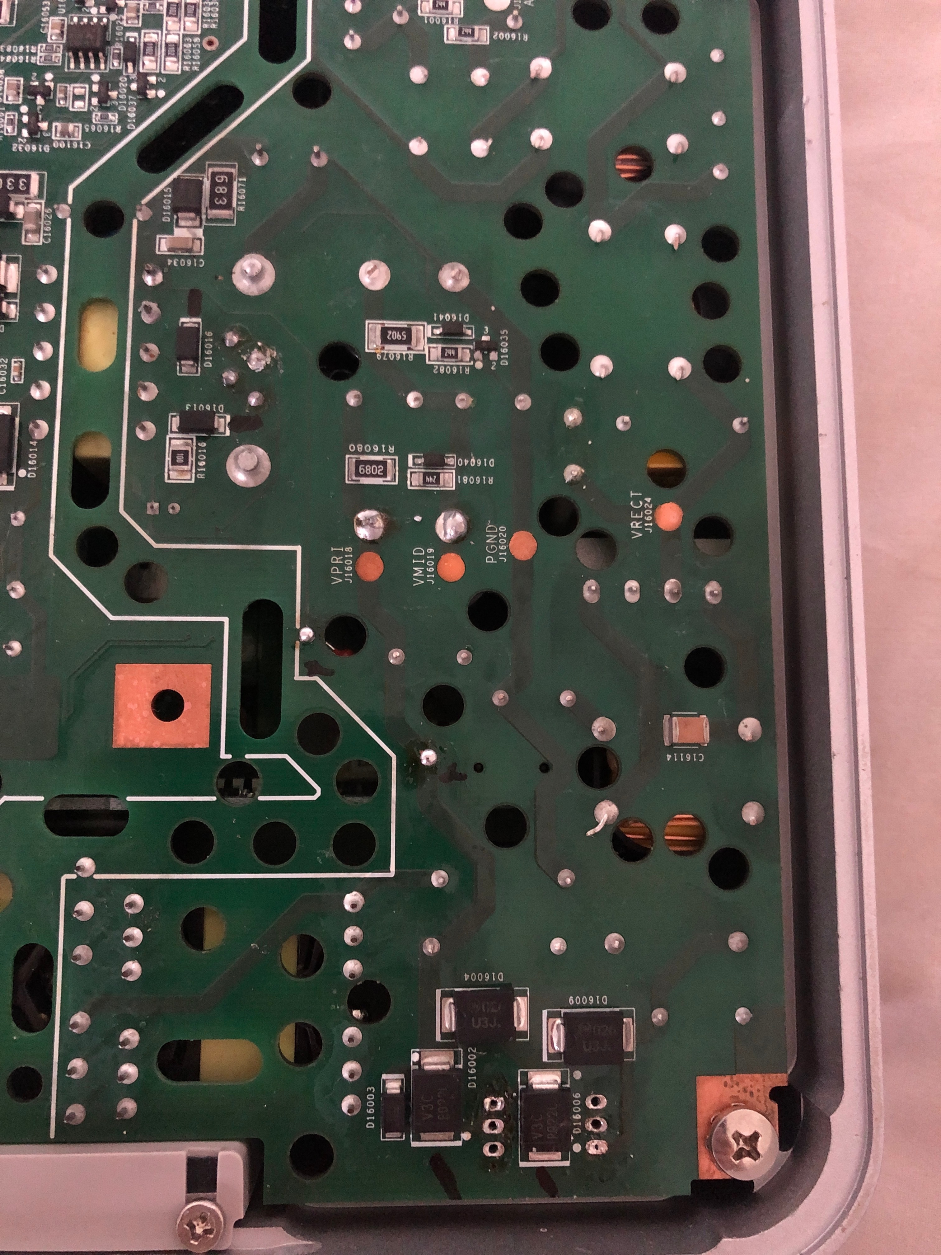
I have noticed that the 4 diodes (marked with black stripe) do not give any Reading on my multimeter.
- Lyricist III
- January 8, 2022
Update: removed almost all diodes from underside op primary side. Theyre all Good. Something I noticed is that all the 5 points of this winding in the secondary side are shorted together, is this right?
- Prominent Collaborator I
- January 13, 2022
Hello, im from Germany and need your Help.
These two capacitors are defective. do you know the data for these?
TH16001 and TH16002.
Thank You
Max
Hi guys, I own a connect amp that was plugged (by previous owner) in to 220v when switch was on 110 v.
I replaced the fuse, replaced the TVR14241 (mov) and i noticed that the TH16001 also cracked. I could not source the Sck054 needed to replace this part in my local electronics store, so I hardwired it for now, and everything works perfectly.
Questions are:
- with normal use (no power surge, no wrong voltage), will the unit get damaged if I keep it like that?
- is th16001 used in 220v setup, or is it for 110v only, and th16002 for 220v?
If it will Increase the lifespan of the unit, i will order the SCk054 online.
Thanks for this super interesting group discussion, got me already quite far!
The thermistors here are NTC (negative temperature co-efficient). These will have a higher resistance when cold than once they warm up. I’m not an expert but I think that the purpose is to limit the inrush current when the device is first plugged in. These are used in most sonos devices that drive speakers. Each of these has large capacitors that charge up, and which will draw large amounts of current quickly without the thermistors. You may notice your lights dim a bit when you plug in a device without them. I notice this dimming with the ZP120 Connect:AMP devices, and that’s with the thermistors working!
The thermistors are active in both 110v and 220v devices.
- Prominent Collaborator I
- January 13, 2022
Update: removed almost all diodes from underside op primary side. Theyre all Good. Something I noticed is that all the 5 points of this winding in the secondary side are shorted together, is this right?
The secondary winding has two separate coils. The first is across three pins with a centre tap. Within each coil (the first 3, or the second two pins), you should measure a very tiny resistance (under 1 ohm) between the pins -- this is normal for a transformer. The short between the two coils is not normal. You may have a short between the two secondary coils, or it could be ‘downstream’ of that.
I’ve fixed dozens of these devices and haven’t seen this particular problem before. You can try to remove the transformer and see if the dim bulb stays bright. If it does then the transformer is probably not the problem. Be warned though… Getting that transformer out and then re-installed is a pain to do.
- Lyricist I
- November 10, 2022
I replaced the fuse, replaced the TVR14241 (mov) and i noticed that the TH16001 also cracked. I could not source the Sck054 needed to replace this part in my local electronics store, so I hardwired it for now, and everything works perfectly.
If you cannot easily source a SCK054, there are similar devices available, eg:
- SCK054 Specs:
Zero power resistance at 25 deg C = 5 ohm
Max steady current at 25 deg C = 4 Amp
Approx resistance at 25 deg C = 0.18 ohm
Thermal dissipation constant = 17
Thermal time constant = 33 sec
- TDK B57235S0509M0 (RS Part number 467-614)
Zero power resistance at 25 deg C = 5 Ohm
Max steady current at 25 deg C = 4.2A
Approx resistance at 25 deg C = 0.11 ohm
Thermal dissipation constant = 9
Thermal time constant = 60
- Yageo NTD04-005M (Element14 order code 3770791)
Zero power resistance at 25 deg C = 5 ohm
Max steady current at 25 deg C = 4 Amp
Approx resistance at 25 deg C = 0.182 ohm
Thermal dissipation constant = 9
Thermal time constant = 48 sec
- Lyricist I
- December 1, 2022
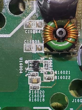
Сould you please tell me the value and marking of the resistor R16021?
- Prominent Collaborator I
- December 1, 2022
That looks like it is labelled “31B”. EIA-96 says that’s a 2.05k resistor: https://www.hobby-hour.com/electronics/eia96-smd-resistors.php
I measured in circuit, and got 1k. Perhaps it is in parallel with the one next to it.
- Lyricist III
- January 21, 2023
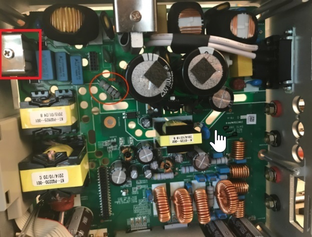
Hi! I found some time to work on this project again. I had a blown 10 ohm resistor and a bad PWM, switched both and blew again. I saw some black marks on one of the yellow caps between the two big caps and replaced those with a new PWM and now the light bulb goes out. Yay. Still no white light though. I did not measure anything on the measure points on the secondary side though. Also these 2 transistors were getting quite hot (but I suppose that’s due to the missing heat shield, case).
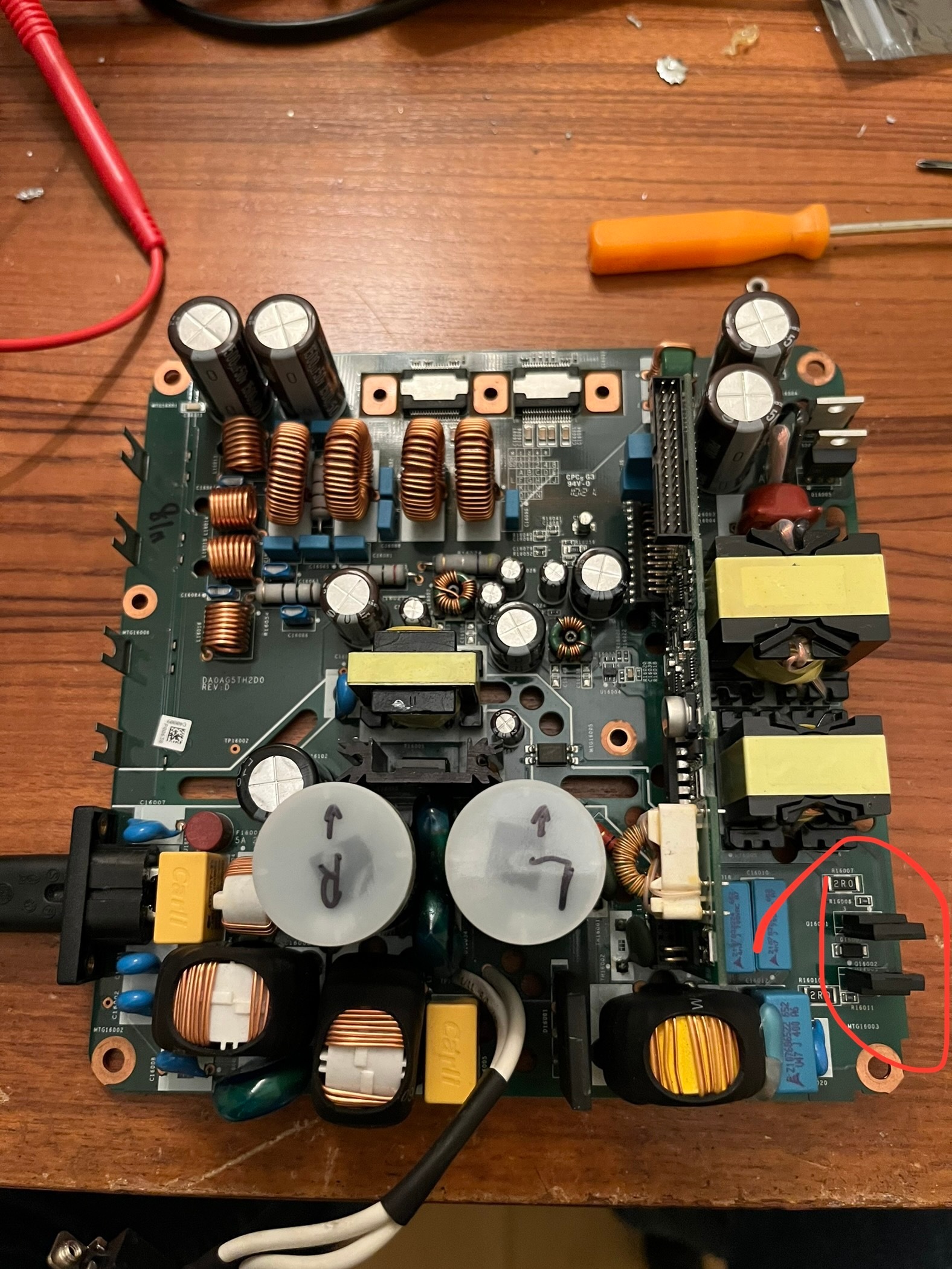
I think these are for the 36v which should not be on at that time? -Edit: I now noticed that the other diodes are for the 36v rail- I replaced these 4 diodes (2 pairs that are using case as heat shield). Rectifier is also good, amps don’t seem to be shorted. My only thought at this moment is the feedback unit. Do these even go bad? I would love to hear some thoughts. I will do further testing as I did not measure too much because noticed the diodes getting hot.
- Prominent Collaborator I
- January 21, 2023
Hi! I found some time to work on this project again. I had a blown 10 ohm resistor and a bad PWM, switched both and blew again. I saw some black marks on one of the yellow caps between the two big caps and replaced those with a new PWM and now the light bulb goes out. Yay. Still no white light though. I did not measure anything on the measure points on the secondary side though. Also these 2 transistors were getting quite hot (but I suppose that’s due to the missing heat shield, case)
I think these are for the 36v which should not be on at that time? -Edit: I now noticed that the other diodes are for the 36v rail- I replaced these 4 diodes (2 pairs that are using case as heat shield). Rectifier is also good, amps don’t seem to be shorted. My only thought at this moment is the feedback unit. Do these even go bad? I would love to hear some thoughts. I will do further testing as I did not measure too much because noticed the diodes getting hot.
I wonder if you’ve misidentified some components.
The two “yellow caps” located between the big capacitors are not actually capacitors. They are varistors (or MOV for metal oxide varistor). These have high resistance, but as voltage rises their resistance drops. In the event of a voltage spike, these shunt excess voltage away from the circuit, acting as protection devices. If they are dead then it is very possible your device suffered a voltage surge. If so then this is recoverable, but there may be multiple component failures.
You said that you replaced 2 pairs of transistors. The first pair are transistors and you need matching components (part number K13A60D). The second pair are not transistors - they are dual diodes (part number SBR10100).
When you say it ‘blew again’, how fast was that? Was it right away, or only after trying to play some music?
The first two transistors you mention are part of the 36V circuit. When the device is idle (or even playing at very low volume), the amplifier is run off of a 14V supply that comes from the central transformer (which is driven by the PWM). Once the volume is turned up, then the 36V circuit comes on. That is where these two transistors come into play. They are switched via signals that come from the mainboard, through the riser board, then out the small plug in connector on the end of the riser board. Since this is part of the 36V circuit, you should be able to get the device working (albeit perhaps without any audio being produced), even if these are damaged.
You need to know if the PWM and transistors are actually working or not. If you use a multimeter in diode test mode, you can look between each pair of pins (eg 1-2/1-3/2-3/2-1/3-1/3-2). You need to test all pin combinations in both directions. You want to see either an open circuit, or a small voltage like 0.6V. If you get any shorts then the device is bad.
Ideally, if you can get it running with the dim bulb, then you can check the back side for the various bias voltages. There are test points marked for GND, 5V, 3.3V, 14V, and GND36/36V (the 36V points may measure 15V and that’s ok). You don’t need the riser board or main board connected to test these voltages.
Enter your E-mail address. We'll send you an e-mail with instructions to reset your password.
Scanning file for viruses.
Sorry, we're still checking this file's contents to make sure it's safe to download. Please try again in a few minutes.
OKThis file cannot be downloaded
Sorry, our virus scanner detected that this file isn't safe to download.
OK