
The amp has no power. Is there an internal fuse for this unit?
Has anyone taken one apart?
Repair ZP120
- August 3, 2010
- 407 replies
- 46624 views
This topic has been closed for further comments. You can use the search bar to find a similar topic, or create a new one by clicking Create Topic at the top of the page.
407 replies

- Prominent Collaborator I
- April 23, 2020
That was it! I replaced the shorted diode with a 1n4148 as that's all I had on hand. No more orange light and she sings!
I have to thank everyone that participated in this thread, wouldn't have gotten her working without your help.
Congrats!
It looks like that component may be a zener with a working voltage of 2.1-2.3V (google philips bzx399). The 1n4148 is a switching diode, so it might behave a little differently. For example, the 36V section may be constantly ‘on’ rather than off during standby. If you get any more issues you may want to find a more similar part.
I had a quick look at my units that have been having similar issues, and sadly this part is fine on them.
Thanks for closing the loop on this.
- Lyricist III
- April 23, 2020
I'll check if the 36v turns back to 15v at standby. It's only temporary until I find the matching part..
Have you tried yours with a known working riser board and logic board? I'd like to still know more about the orange light error. Seems with all voltages correct the orange light refers to the riser/logic board or amp chips.
I have a Gen 2 Play 5 that has a short on the power supply. Doesn't seem to be much info out there on them.
- Prominent Collaborator I
- April 23, 2020
Here’s a similar issue that your info helped me solve (I’m 99% sure)...
This is the same board that I posted an image of a couple of days ago. I had replaced some damaged components, and after that it would do the white/off/yellow/off cycle when I tried to play.
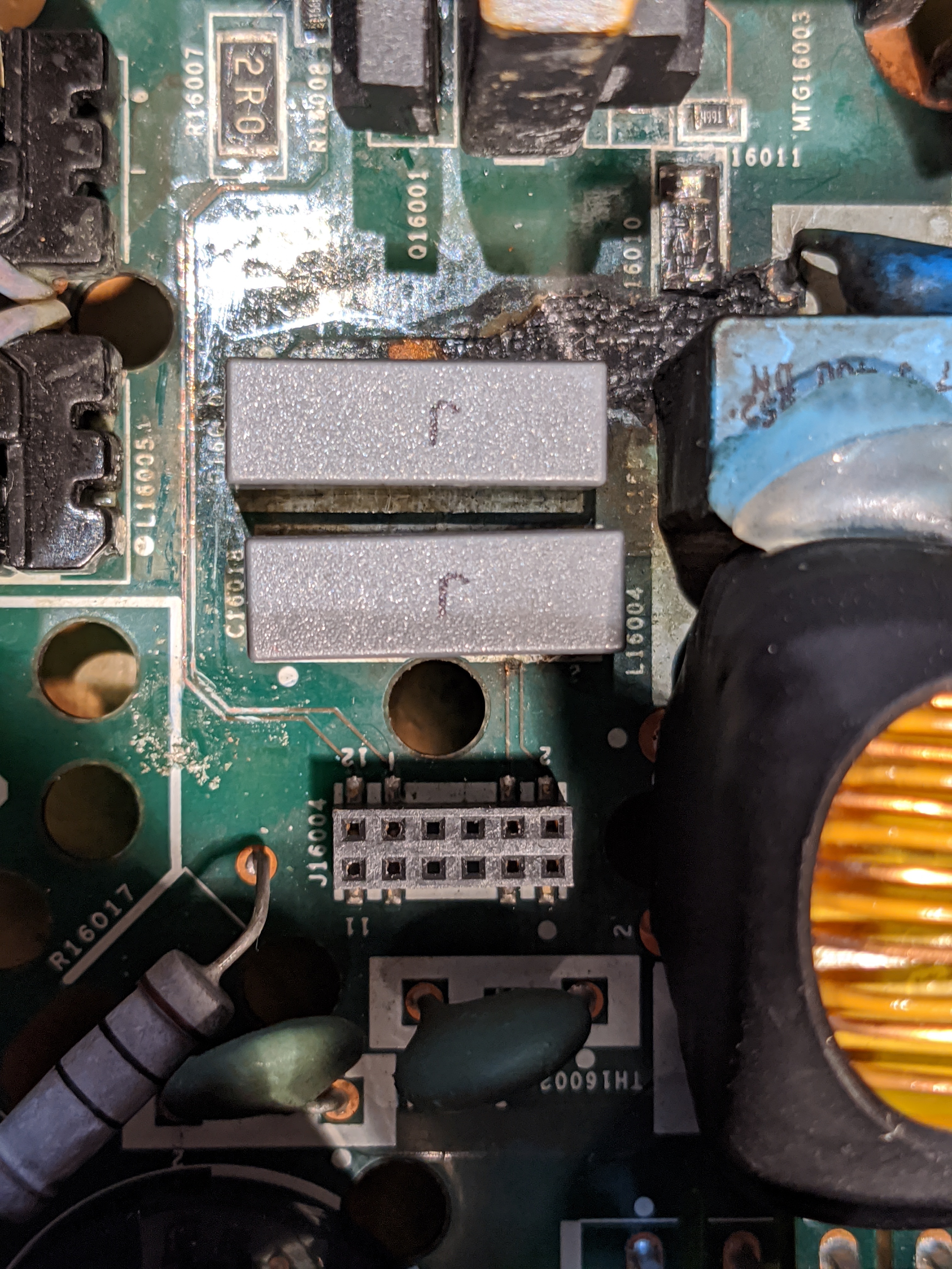
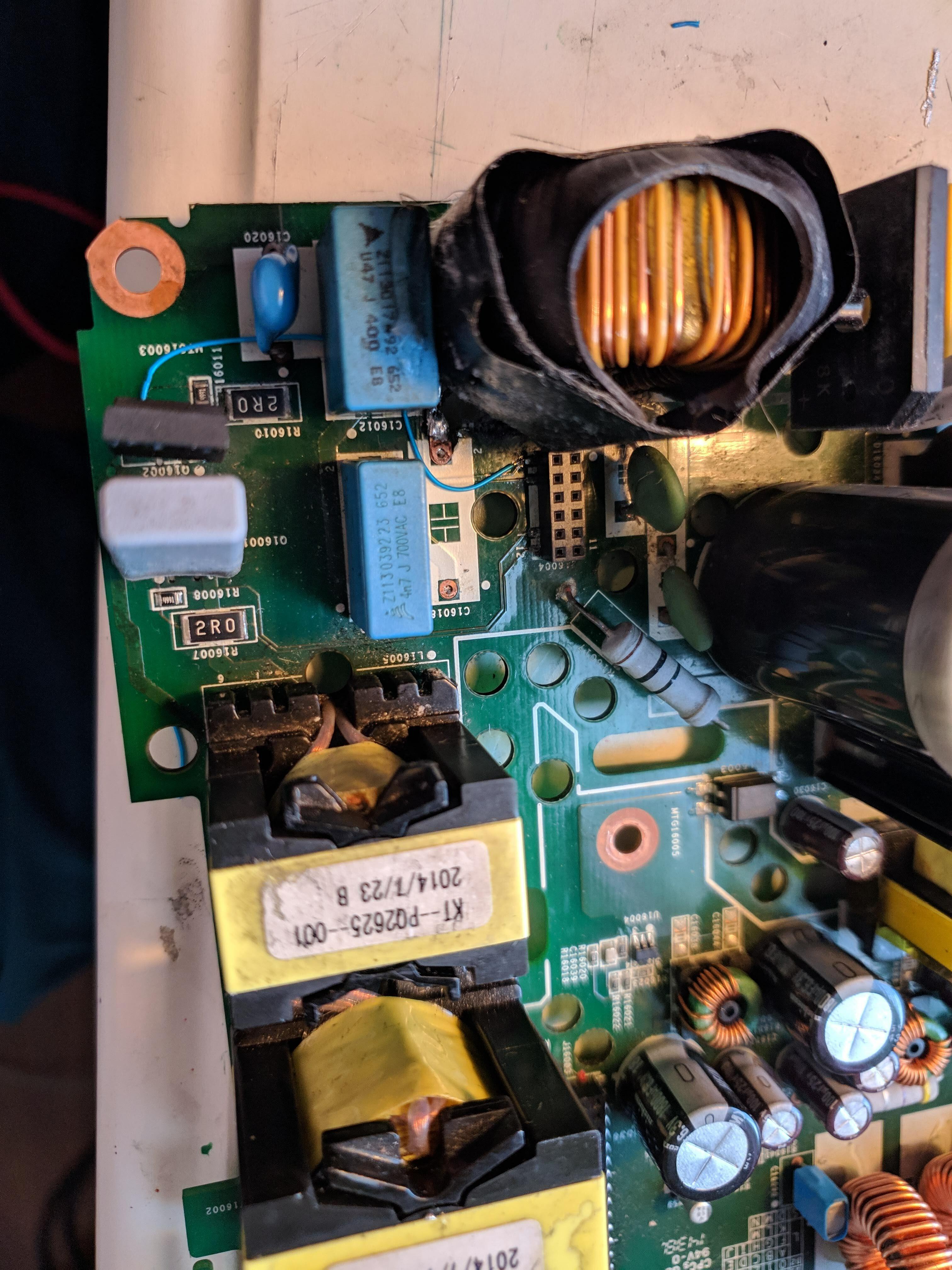
The 2 traces that run vertically between the transformer on the left and the two grey capacitors on the right connect two pins from the riser connector up to the MOSFETs above. They are damaged (confirmed with a continuity check) - it looks like the power surge the board suffered must have caused them to blow up.
I wouldn’t have found this so quickly without your success, shtnarg! I imagine I’ll have to replace that crispy looking R16010 on the top right as well -- it seems to be in the path back to the riser connector.
- Prominent Collaborator I
- April 23, 2020
I'll check if the 36v turns back to 15v at standby. It's only temporary until I find the matching part..
Have you tried yours with a known working riser board and logic board? I'd like to still know more about the orange light error. Seems with all voltages correct the orange light refers to the riser/logic board or amp chips.
I have a Gen 2 Play 5 that has a short on the power supply. Doesn't seem to be much info out there on them.
Yes I have seen the 36V fall back. It doesn’t happen immediately but it does eventually.
My issue is on the power/amp board - see my other recent post.
I have a few gen1 play:5s but no gen2. The gen1 play5s are actually pretty horrible to try to fix. There is a massive buildup of heat in them when they are in use, and it causes a variety of different failures. The enclosure is basically a box with only one small bass reflex opening -- not great for air circulation.
- Lyricist III
- April 23, 2020
Well done!
I put mine back into the shell to clear it off my desk. Forgot the volume/mute buttons, so I did that twice, including those F****** clips!
And of course the orange light is back.
sigh
- Lyricist III
- April 23, 2020
Be warned once again RE those terribly designed stubborn clips. I saw gruvs post about Bending the pins on the MOSFETs when putting the clips back on. When I reassembled, I didn't use the little condoms Sonos included and just had the clip on the metal of the shottkey diodes (D16005). guess that was shorting the 36V line again. back to fully operational.
- Prominent Collaborator I
- April 24, 2020
I put mine back into the shell to clear it off my desk. Forgot the volume/mute buttons, so I did that twice, including those F****** clips!
And of course the orange light is back.
Third time’s a charm!
- Prominent Collaborator I
- April 29, 2020
Here’s a similar issue that your info helped me solve (I’m 99% sure)...
Well, no joy - but oh so close…
I ran 4 jumpers where those traces should be (there are four total connections from the small power supply area to the riser - all four jumpers were destroyed. I replaced the dead resistor too. I also had to bridge the two grounds on the secondary side. This is all on top of having already replaced some capacitors, and the two mosfets.
It booted up ok, but when I hit play I still get the white/orange cycle.
The difference this time is that the 36V section of the secondary does ramp up to 36V momentarily after I hit play. Once the yellow comes on it falls back to 15V.
The real surprise (to me) is that there is only 280V on the primary side of the supply instead of the usual 320V. That tells me that there is either still something wrong there, or there is some kind of power draw on the secondary side that is preventing the primary from reaching 320V. I disconnected the 15v/8v section of the secondary and tried again -- this time the primary gets to 306V. I think that this means the primary isn’t generating enough power to drive the load properly… My logic is that if there was a short on the 3.3V rail, I should still get 280V, and if there was a short on the 15v/5v rails then I should get 320V.
I’ll keep looking but honestly I’ve been through this one pretty thoroughly so don’t know what to look for any more.
I have another ZP120 that is now showing similar symptoms (including 280V on the primary) but arrived to its condition via a different route. That one had a bad transformer primary. I removed the transformer and found that its winding connections had rusted away. I was able to get them reconnected, but it was microsurgery and I must have damaged something. When I reinstalled it, it now boots ok but also goes into the white/yellow cycle when I press play. I think that the primary winding got shorted and it just isn’t generating enough voltages on the secondaries to make it work.
The other possibility for both of these is that the amp chips are fried. I probably don’t have much to lose to try replacing those at this point.
- Prominent Collaborator I
- April 30, 2020
Well, no joy - but oh so close…
It booted up ok, but when I hit play I still get the white/orange cycle.
I’ll keep looking but honestly I’ve been through this one pretty thoroughly so don’t know what to look for any more.
Actually… I feel so dumb… I still had my dim bulb in the circuit. Once I removed it everything worked beautifully!
I fixed all four zp120s that I described 10 days ago: https://en.community.sonos.com/advanced-setups-229000/repair-zp120-17442?postid=16419707 .
This included one with multiple rusted traces, another with a rusted transformer winding, one with two bad schottkys, and one with a bad PWM. There was other collateral damage too (diodes, caps, etc) but those were the dominant issues on each.
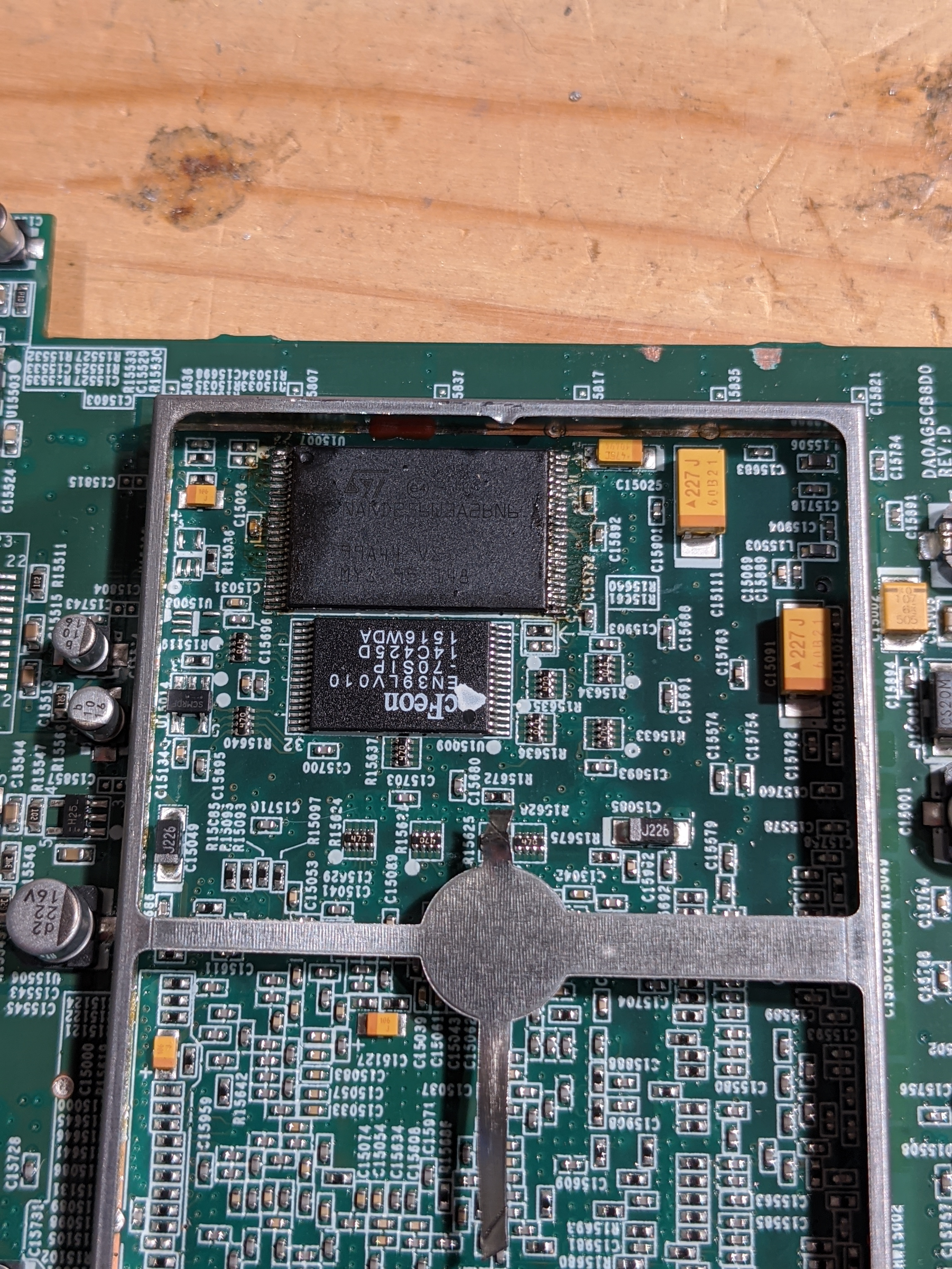
I also tried fixing a wifi/logic card, but was unsuccessful. I had one card that showed a dead short, and another that had a bad NAND chip. I moved the NAND chip from the card with the short to the other card, but it wasn’t recognized. It turned out that the good chip was ‘legacy’ and was a 64MB chip while the other NAND that it was replacing was ‘modern’ and was 128MB. It gave a message of ‘no NAND found’ in the UART, so I’m pretty sure it just doesn’t recognize the chip.
- Prominent Collaborator I
- May 2, 2020
I also tried fixing a wifi/logic card, but was unsuccessful. I had one card that showed a dead short, and another that had a bad NAND chip. I moved the NAND chip from the card with the short to the other card, but it wasn’t recognized. It turned out that the good chip was ‘legacy’ and was a 64MB chip while the other NAND that it was replacing was ‘modern’ and was 128MB. It gave a message of ‘no NAND found’ in the UART, so I’m pretty sure it just doesn’t recognize the chip.
I looked closer at the boards. The two boards did have different DRAM and NVRAM (with the ‘modern’ device having twice the capacity of legacy for both DRAM and NVRAM). However, they did have the same ROM chip (the 512k EN29LV040). So in addition to moving the NAND chip from the legacy board to the modern one, I moved the ROM chip too. After this, the logic card booted correctly!
U-Boot 1.1.1(1-16-3-0.9), Build: 0.9
MPC8272 Reset Status: External Soft, External Hard
MPC8272 Clock Configuration
- Bus-to-Core Mult 3x, VCO Div 4, 60x Bus Freq 16-50 , Core Freq 50-150
- dfbrg 1, corecnf 0x10, busdf 3, cpmdf 1, plldf 0, pllmf 3
- vco_out 400000000, scc_clk 100000000, brg_clk 25000000
- cpu_clk 300000000, cpm_clk 200000000, bus_clk 100000000
- pci_clk 33333333
CPU: MPC8272 (HiP7 Rev 14, Mask unknown [immr=0x0d10,k=0x00e1]) at 300 MHz
Board: Sonos Wembley
DRAM: 32 MB
DRAM test
Test complete - 0 errors, error pattern 00000000
Using default environment
In: serial
Out: serial
Err: serial
Net: FCC2 ETHERNET
Hit any key to stop autoboot: 0
NAND ID is 20:75
32M NAND flash (ST NAND256W3A)
S0 provisionally good, KP=1, G19
S1 provisionally good, KP=4, G18
Boot from partition 1
## Starting application at 0x00400000 ..▒TTTTTTTTTTTTTTTTTTTTTTTTTTTTTTTTTTTTTTTTTTTTTTTTTTTTTTTTTTTTTTTTTTTTTTTTTTTTTTTTTTTTTTTTTTTTTTTTTTTTTTTTTTTTTTTTTTTTTTTTTTTTTTTTTTTTTTTTTTTTTTTTTTTTTTTTTTTTTTTTTTTTTTTTTTTTTTTTTTTTTTTTTTTTTTTTTTTTTTTTTTTTTTTTTTTTTT...........................…
It is only recognizing 32MB of DRAM despite the card actually having 64MB, but that’s what I would expect given the ROM and NAND chips came from a legacy device that has only 32MB.
I’m definitely a happy camper, having salvaged a working logic card from two previously dead ones! here’s a pic of the board after I swapped the NAND chip (but before I swapped the ROM)

- Trending Lyricist I
- May 2, 2020
Hi All,
I wish all of you guys are doing OK. I am the one fixed the broken transformer about 1 year ago.
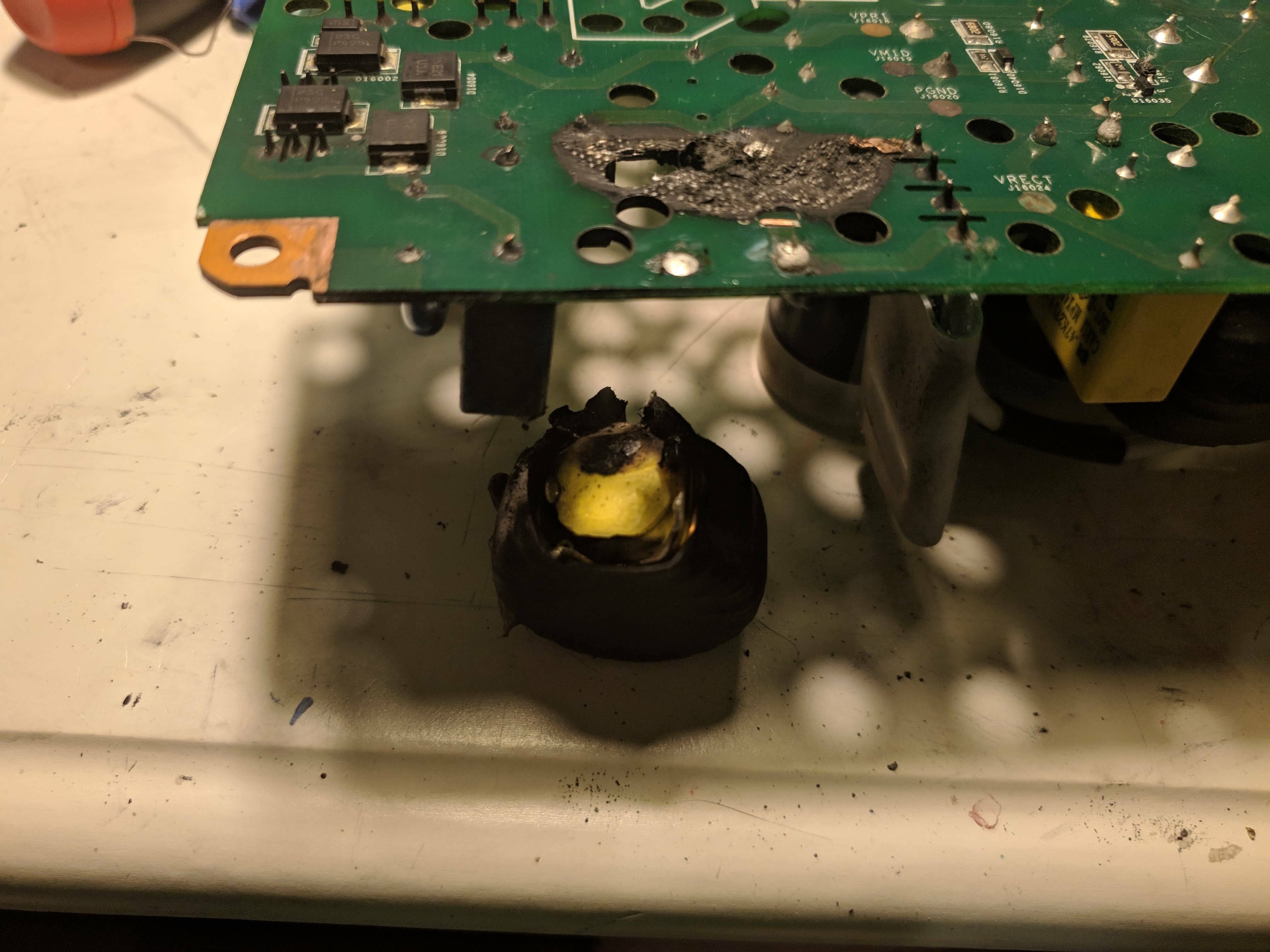
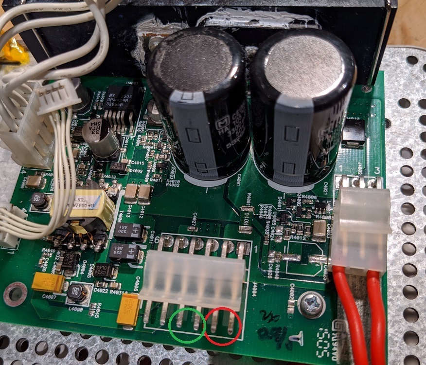
I figured I will try more repairs during this lockdown just for fun. I got one SONOS AMP off eBay with power up failure. After opening the AMP, I am shocked to see there is a black burn around the input rectifier. The inducter after is completed blown!
I managed to fix the inductor and now my Amp is back online in the SONOS AMP. Right after I start playing music, the LED turned from solid white to flashing white and amber! It indicates the AMP is bad.
I check all my voltages and everything is OK except the 36V stuck at 15V even after play starts. I think something is wrong for the 36V regulator. Any tip to diagnose that part of the circuit?
Thanks,
Benbendog
- Prominent Collaborator I
- May 2, 2020
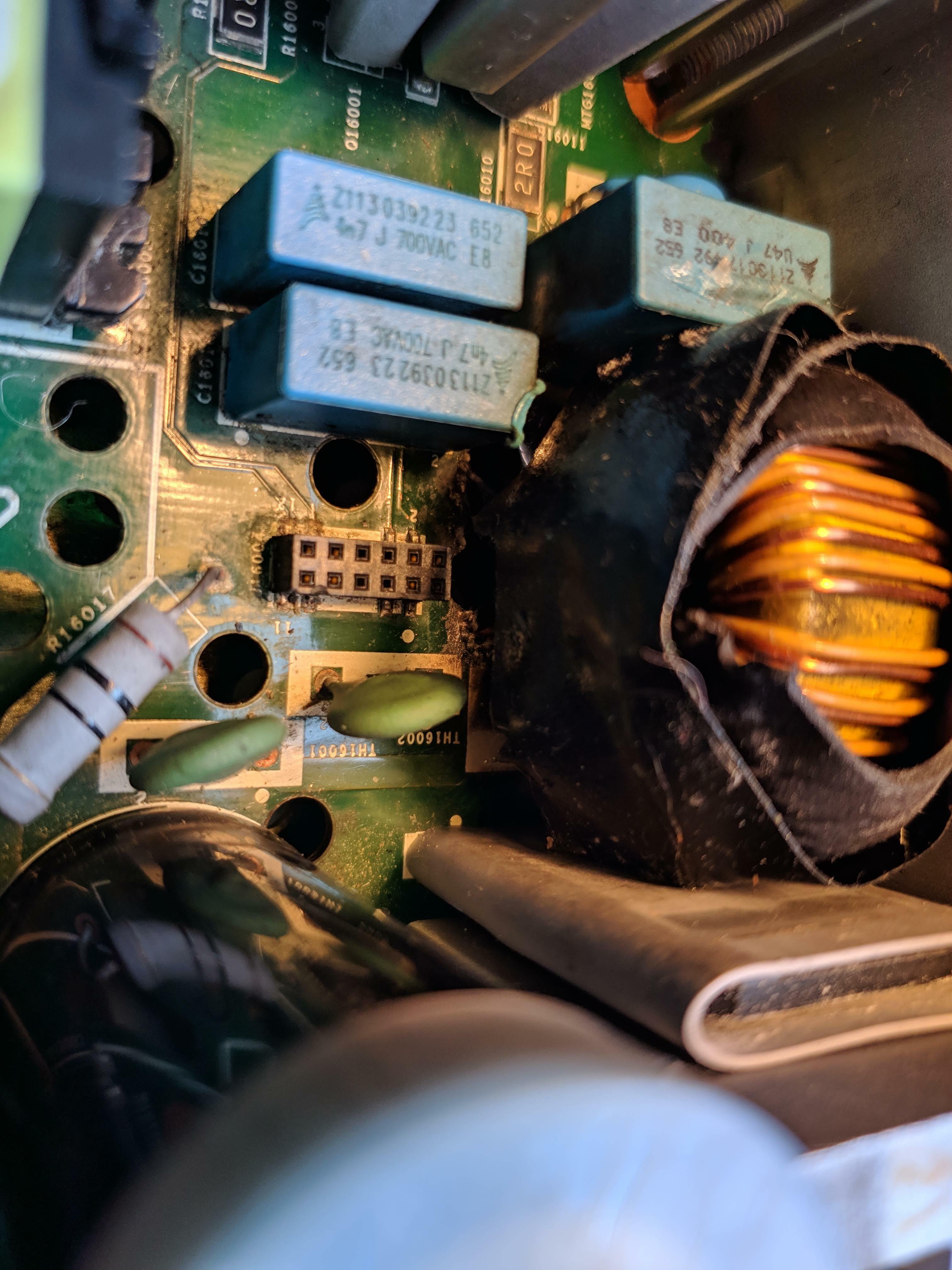
From the 36 volt test point, you can try to trace backwards. There are two schottky diodes behind one of those nasty clips towards the back of the board from the 36v point. The 36 volt and ground pass through an inductor before they reach those diodes. Each 3 pin schottky diode package has two diodes and all four of the diodes are in parallel. Check the diodes. Note that the 36 volts does not come on until you press play, so you can't expect 36 volts all the time.
I have found problems here, as well as these short connector on the riser board. The input to the 36 volt supply passes up on that riser connector are is processed on the riser. There are 8 henpins on the connector but only four signals (they are in pairs for amperage I think). When 36v is needed, that circuit that will pass it down through the riser board back to the main board.
- Trending Lyricist I
- May 2, 2020
I am glad that I figured out after reading all the other posts in this thread, it is really helpful:
It turned out the burned PCB indeed destroyed one of the traces from the rise card to the 3 pin diode. I could not really visualize it but the meter told the truth. I removed two capacitors and solder a thin blue wire as you can see in the picture.
With this fix and as soon as I start playing music, I did get 36V and the white/orange flashing is gone.
It is amazing with such bad burn in the inductor that the PCB got a hole underneath it but no other components were damaged including the fuse!
Thanks again for this informative thread.

- Avid Contributor I
- May 10, 2020
I have a ZP100 that I think took a power surge, perhaps through the RJ45 port. After that event, the unit would power up, the white light would flash forever & there was no network activity on any of the RJ45 ports.
I recently had another ZP100 go out, so I took the CPU board from that device and swapped it into the first one. I powered it up, RJ45 ports work, it gets an IP and shows up on the Sonos app (as the “donor” ZP, naturally). However, when I go to stream anything (local music or through a service) it tries for a while & then I get a message like “Can’t play this station” from the app. Is there something else I need to do on the player to get it to stream properly?
- Prominent Collaborator I
- May 11, 2020
I recently had another ZP100 go out, so I took the CPU board from that device and swapped it into the first one. I powered it up, RJ45 ports work, it gets an IP and shows up on the Sonos app (as the “donor” ZP, naturally). However, when I go to stream anything (local music or through a service) it tries for a while & then I get a message like “Can’t play this station” from the app. Is there something else I need to do on the player to get it to stream properly?
When you say that you had another “ZP100 go out”, how did that device fail? If you moved the logic board from that device to the one that had the blown ethernet, perhaps it is broken in another way?
Do other music sources work? Or does the device alternately flash white/orange? One easy way to test comms from your phone to the device is just to mute the device from your phone. If it is receiving messages then the mute light will come on.
- Avid Contributor I
- May 11, 2020
I actually don’t know why the donor device stopped working. One day it was just dead, no power/flashing light on reboot.
I don’t know that the donor board is good. But it seems odd that after replacing it into another ZP, which prior to the swap would just flash white mindlessly forever, now appears on the network and does everything up to tuning a stream, it just won’t play it out.
As I mentioned, the device shows up on my app, I can communicate with it via the app (mute/unmute, turn the indicators on/off, rename, select streams, etc.). It just fails to connect to the stream & play anything out. I get the same results if I try to play something from my local music library.
Also of note, if I go to Sonos.com & select “my system” it shows up there as well as “Online”. So I think connectivity is ok. What I’m wondering is does the ZP “engage” something else when it gets ready to play out? Does it for instance try to crank up the amp at that point, and if that fails for some reason is this the type of message I would get?
- Prominent Collaborator I
- May 13, 2020
Also of note, if I go to Sonos.com & select “my system” it shows up there as well as “Online”. So I think connectivity is ok. What I’m wondering is does the ZP “engage” something else when it gets ready to play out? Does it for instance try to crank up the amp at that point, and if that fails for some reason is this the type of message I would get?
It definitely seems like the logic board you moved is operational, but I have never seen this kind of persistent failure to play.
When you hit ‘play’, the device activates a different power circuit that is used to drive the amplifiers. This is the 36V circuit. (this circuit is in standby when the device is not in use to reduce power consumption). I have seen two common problems… One is that the 36V circuit doesn’t come on like it should, and the other is that the amplifier chips are blown or damaged. In both of these cases, the device starts to flash white-off-yellow-off, and the volume slider in the app is reduced to about 15% if it was above that level. Usually there is no sound playing, but within the app the source shows as playing.
Your issue does not seem to be a hardware problem (as you never mentioned the flashing light sequence).
It’s a long shot, but do you have a firewall or blocklist of any sort? I would think that at least your local sources wouldn’t be affected but perhaps there is some kind of issue connecting to the Sonos servers.
What you should do is contact Sonos. There is an option inside the app to send a diagnostic to them (they will walk you through when and how to do this), and then they can then diagnose what exactly is going on.
- Avid Contributor I
- May 13, 2020
Thanks for the reply, I’ll check the behavior again but I don’t remember the seeing the light sequence or the volume slider moving.
I’m wondering if it has something to do with the MAC(s) in the donor CPU board not being what the rest of the system expects or something (not sure what other parts of “the system” would care outside of the CPU board, though).
In terms of the network, both ZPs had been offline for many days so any ARP caching or other router MAC to IP associations should be aged out at this point. I guess I can try to auger out my router’s DHCP in case there’s something persistently munged up there.
Will Sonos support even acknowledge the existence of a ZP 100 at this point? :)
- Prominent Collaborator I
- May 13, 2020
The MACs are not an issue (I have moved the boards as you describe multiple times).
Support will still talk to you. I actually had them help me get a CR200 working less than a year ago, and that device hasn’t been sold for 8 years now. That required them to remotely log in to the device and provide customized update files, as the device was so out of date that it couldn’t be updated from the main site. I was very impressed.
- Avid Contributor I
- May 18, 2020
Working with Sonos tech support right now, but so far it’s been, “is it on? Move it to WiFi...connect it directly to the router...etc. so not hopeful for a solution from them at this point.
In the meantime, are there test points where I can check for this 36VDC and/or other voltages to see if my amp section is at least attempting to engage when I hit play?
- Prominent Collaborator I
- June 9, 2020
In the meantime, are there test points where I can check for this 36VDC and/or other voltages to see if my amp section is at least attempting to engage when I hit play?
I’ve forgotten where the switching on occurs in the unit. However, I did have a power board lying around and took some measurements. You should find 36V between the labelled pins.
- Trending Lyricist I
- December 8, 2020
Hey everybody! It’s been a while.
I just found something that is contrary to something i have said over and over in these forums. I have a AMP (1st gen version) that had the 36V transformer winding return shorted to the 5V winding return. I shorted them like i suggested in many posts in this thread.
The amp functions fine.
What i noticed was that in the time delta between the 36V coming on and the sound starting there was quite a bit of noise. Normally i use these things in noisy environments and i don’t hear that noise at all. But now in my quite home office that noise really bugs me. I removed the short and not only does the unit still function, but the noise is gone.
I am not sure how this thing works without the 36V and the low voltage biases returns tied together, but it does on mine.
Just my 2 cents.
Man how much does recycle mode suck?!?! LOL
Enter your E-mail address. We'll send you an e-mail with instructions to reset your password.
Scanning file for viruses.
Sorry, we're still checking this file's contents to make sure it's safe to download. Please try again in a few minutes.
OKThis file cannot be downloaded
Sorry, our virus scanner detected that this file isn't safe to download.
OK