The amp has no power. Is there an internal fuse for this unit?
Has anyone taken one apart?

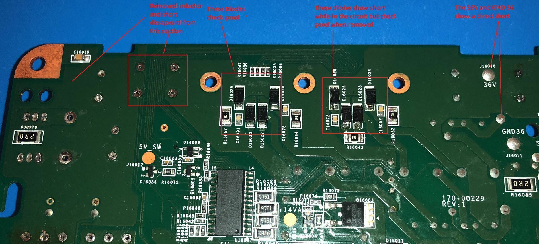
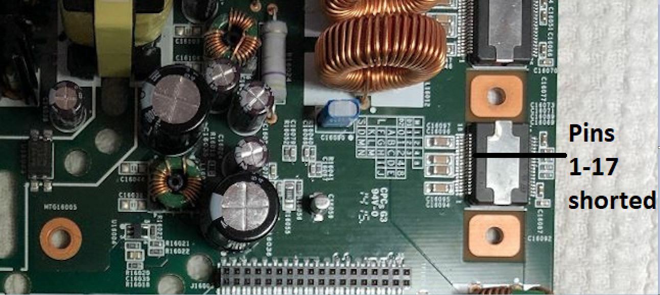
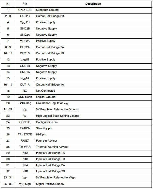
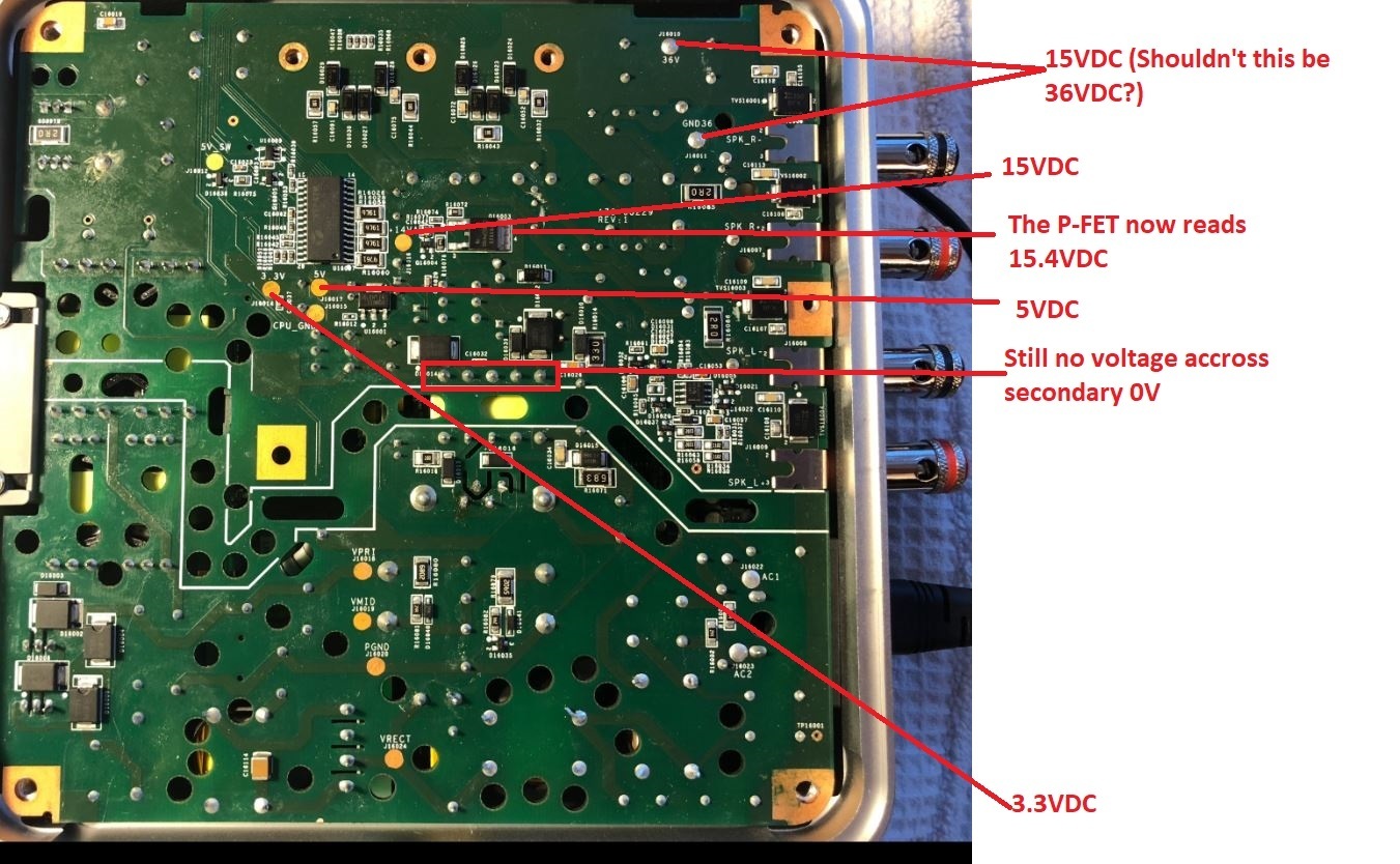
Repair ZP120
This topic has been closed for further comments. You can use the search bar to find a similar topic, or create a new one by clicking Create Topic at the top of the page.


Enter your E-mail address. We'll send you an e-mail with instructions to reset your password.