
The amp has no power. Is there an internal fuse for this unit?
Has anyone taken one apart?
Repair ZP120
- August 3, 2010
- 407 replies
- 48270 views
This topic has been closed for further comments. You can use the search bar to find a similar topic, or create a new one by clicking Create Topic at the top of the page.
407 replies
- Lyricist II
- January 27, 2021
Hi Im not tech enough to open and start fixing mine.
Could there be anyone that could fix mine?
Ive talked to Sonos, but no help there. It online and apparently “working” but no sound.
Cables and speakers working fine.

- Prominent Collaborator I
- February 26, 2021
Hi Im not tech enough to open and start fixing mine.
Could there be anyone that could fix mine?
Ive talked to Sonos, but no help there. It online and apparently “working” but no sound.
Cables and speakers working fine.
PM me - maybe I can help.
- Lyricist II
- February 27, 2021
Hi Im not tech enough to open and start fixing mine.
Could there be anyone that could fix mine?
Ive talked to Sonos, but no help there. It online and apparently “working” but no sound.
Cables and speakers working fine.
PM me - maybe I can help.
- Lyricist II
- February 27, 2021
Hi Im not tech enough to open and start fixing mine.
Could there be anyone that could fix mine?
Ive talked to Sonos, but no help there. It online and apparently “working” but no sound.
Cables and speakers working fine.
PM me - maybe I can help.
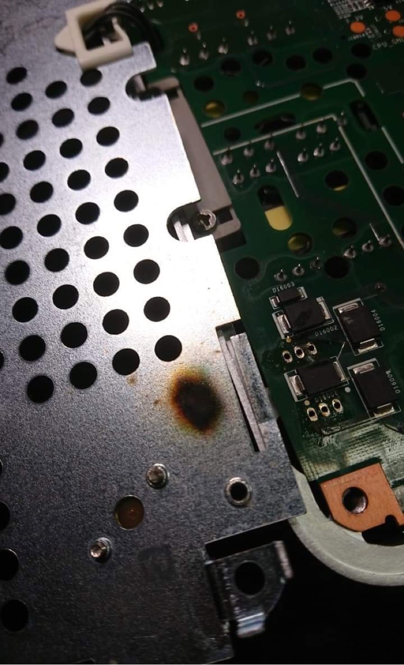
Looks like a lightning has toasted something?
- Prominent Collaborator I
- February 27, 2021
That is likely not beyond repair!
It’s hard to tell from the picture, but there are 6 components under that area and likely at least one of them is bad.
There are four large flat diodes. These can be tested with a multimeter to see what the forward voltage drop is across each. They should conduct power in one direction only.
The other two components are on the other side of the board. They have 3 legs each, and are power mosfets. (like this: http://www.datasheetcafe.com/k3797-datasheet-mosfet/). You can test like a diode between each pair of legs. You should not see any short circuits.
The mosfets are part of the circuit that provides 36V to the amplifier. That 36V is not actually required for the device to power up properly. The fact that you don’t have power means that there is another problem. It could be as simple as the fuse being blown. That is on the other side of the circuit board, and is a small short cylinder about 1cm tall (usually brown).
Do you have a multimeter to test, and have you ever done electronic soldering before?
- Contributor I
- May 31, 2021
I’m in the same boat as most of you (though I haven’t opened up my unit to see what’s going on - I wouldn’t know how to fix it anyway). My unit refuses to power on, and it happened I’m sure “coincidentally” right after I updated my app.
Here’s what it looks like to me: Sonos may have done away with their “recycle” program, but now they’re using “forced obsolescence”, and shutting down older units to force people into upgrading.
My unit - a ZP120 - had been used so infrequently that it should have lasted 40 years. And now, all of the sudden, and right as I updated my app, it goes bad for no reason? And Sonos is telling me that I can’t get another ZP-120 and I have to get one of the newer models.
That’s some sketchy business practices right there.
- Prominent Collaborator I
- June 9, 2021
Here’s what it looks like to me: Sonos may have done away with their “recycle” program, but now they’re using “forced obsolescence”, and shutting down older units to force people into upgrading.
Upgrade to what? The Amp isn’t available to ship until at least Sept. 3. My ZP-120 continues to work fine.
- Contributor I
- August 10, 2021
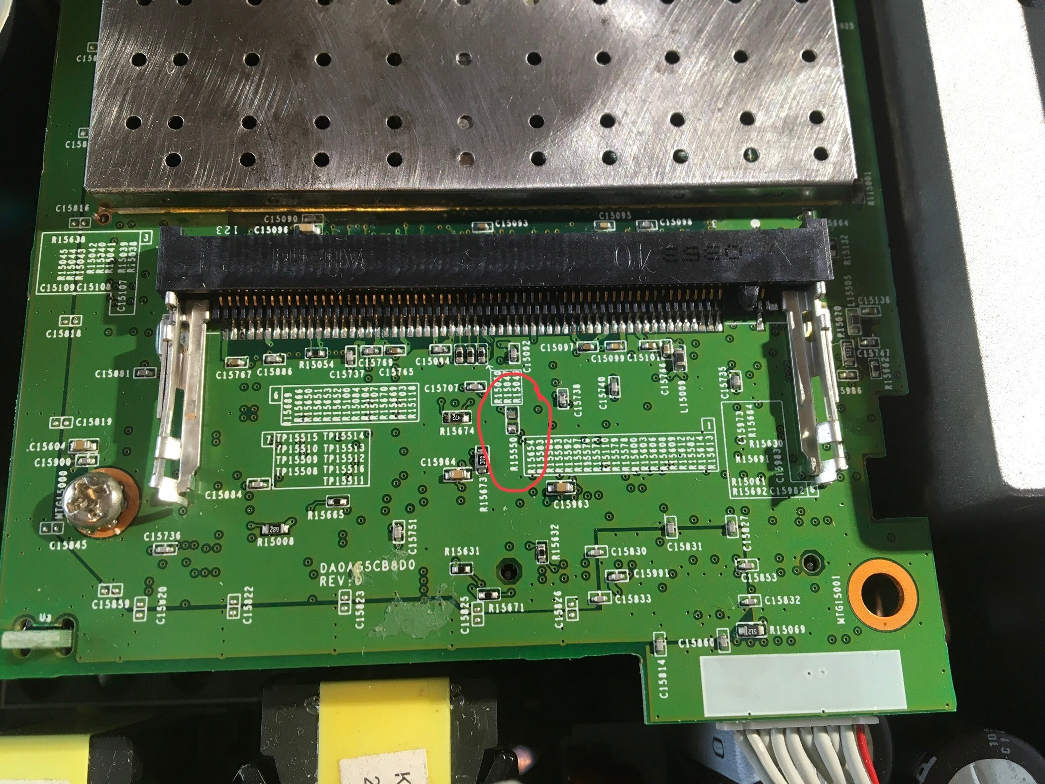
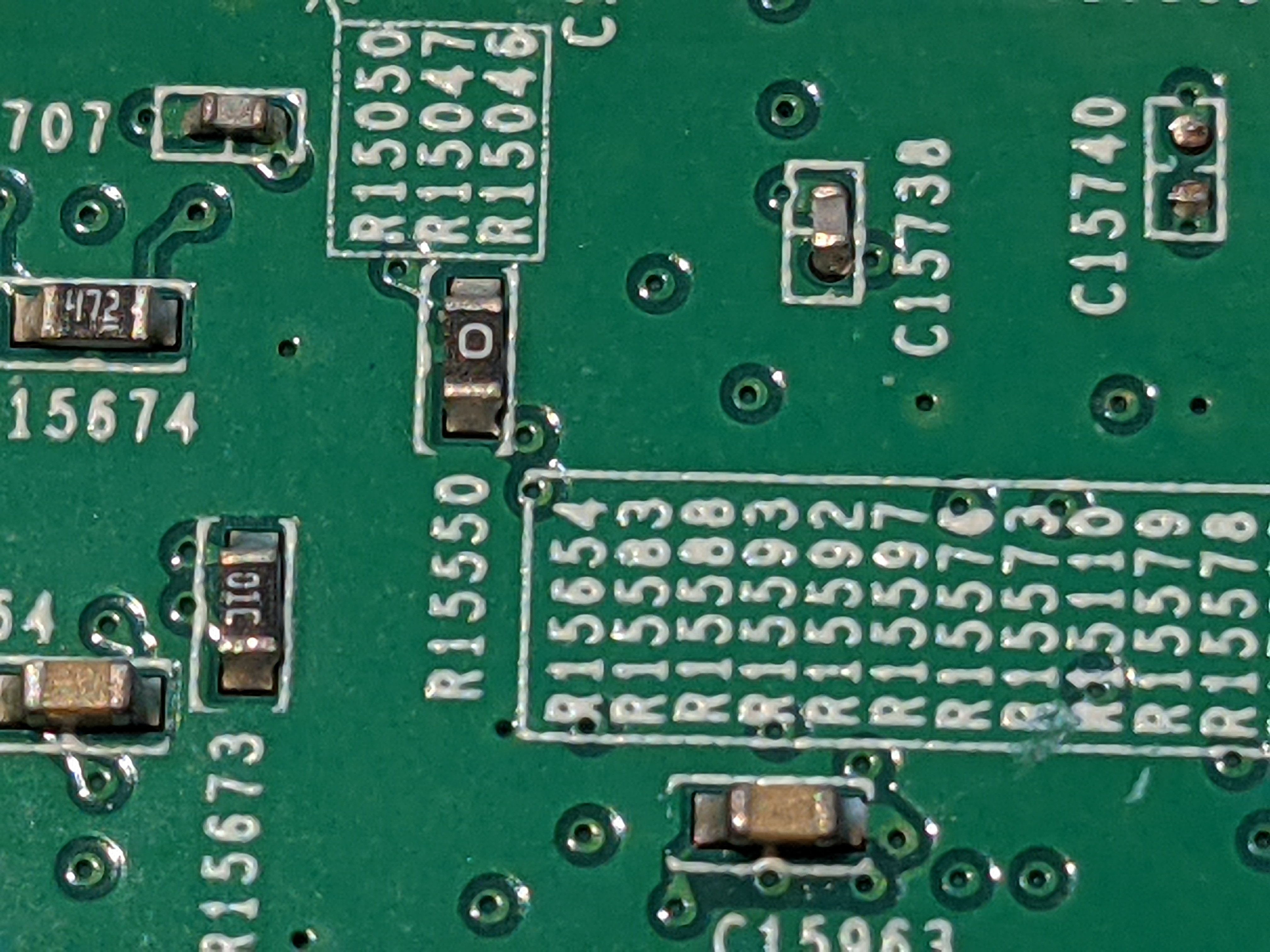
Hi, can anybody tell me the vale of resistor R15550, located under the WiFi module on the ZP120?
This component is missing on my board ( knocked off and lost by previous “repairer”). Oddly, the player still works, but I would like to replace it.
- Prominent Collaborator I
- August 10, 2021
Hi, can anybody tell me the vale of resistor R15550, located under the WiFi module on the ZP120?
This component is missing on my board ( knocked off and lost by previous “repairer”). Oddly, the player still works, but I would like to replace it.
You’re in luck! That’s a 0 ohm jumper, so no parts search required...
- Contributor I
- August 10, 2021
Fantastic, thanks Tim(?).
not often a cheap repair with Sonos!
i’ll go and find a bit of wire now!
Kindest regards,
Andy
- Prominent Collaborator I
- August 11, 2021
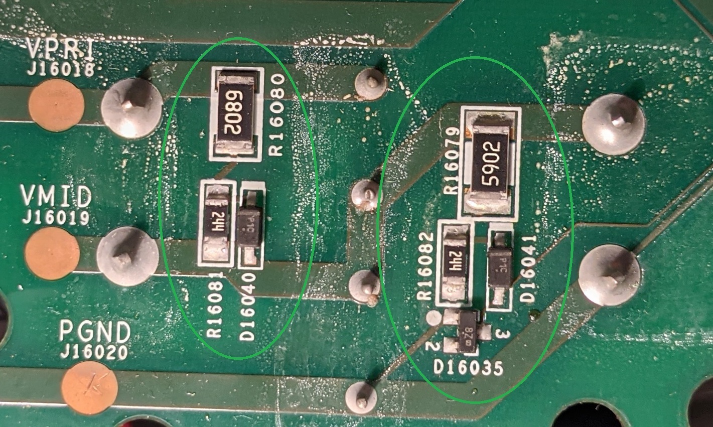
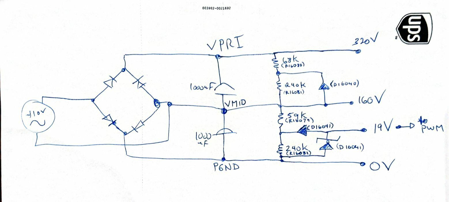
I’m a bit stumped on a ZP120 and am looking for help. The zp120 had a bad varistor, between VPRI and VMID), with lots of scorched bits when it caught fire. It took out the PWM chip, the fuse and a board trace. I’ve replaced those but still can’t get it working properly.
The attached image is from the underside of the zp120 board, below the large capacitors.
I have circled two small circuits in green. The one on the left looks like a bleeder resistor that is intended to discharge the large 1000uf capacitor that sits between VPRI and VMID (about 150V). The 68k and 240k resistors provide 308k of resistance across the capacitor. I thought the small “p1.c” diode is some kind of snubber diode, but I’m not so sure any more, based on what’s going on in the other circuit...
The similar circuit one on the right seems to bleed the 150V between VMID and PGND. That circuit also has the addition of D16035, which sits between the bottom legs of R16082 and D16041. This additional chip is a 19V zener diode in a SOT-23 package. (MMBZ5249B). Pin 3 of this zener diode (which is presumably supposed to be at 19v when the circuit is working property) is the voltage that drives the PWM chip.
My board reads 0V at that junction. I have replaced the zener with no luck. When I provide 16V from an external source, the PWM operates as it’s supposed to. The PWM chip needs 15V to get started, but operates ok with as little as 9V… if I remove my external 16V, the circuit continues to operate (and somehow the circuit now internally generates about 12.5V at the same junction of R16082 and D16041).
I can’t figure out how this circuit works. Specifically, the junction between R16079 amd R16082 reads about 110V when powered up (this seems right given the resistor divider created by R16082 and R16079). I understand that the zener is supposed to clamp that to 19V, but what is the P1C diode (D16041) doing? If it is a regular diode then it wouldn’t pass any voltage to the zener. If it isn’t a vanilla diode, then what is it? I’m guessing D16041 isn’t working but I don’t know what to replace it with. It does not read a voltage drop in either direction when tested (the other P1C reads 0.68V). I can’t find a reference to that marking anywhere.
- Contributor I
- August 11, 2021
Hi, can you sketch the circuit around these diodes out for me?
I would imagine if the other one gives .68v, then it is probably a general purpose silicone diode.
As I say, sketch it out and I'll have a think.
Kind Regards,
Andy
- Prominent Collaborator I
- August 11, 2021
Sure. The attached is how I think the circuit is organized. I don’t quite ‘get’ how the 19V zener is providing 19V in this, but working devices do in fact read 15-18V when running.
D16040 reads with 0.68 forward voltage drop. I wonder if there is a reverse voltage avalanche breakdown property that is allowing some current to pass to the cathode of D16041.
- Prominent Collaborator I
- August 12, 2021
I had a typo: I mislabelled the zener. It is D16035 on the board (not D16041).
- Prominent Collaborator I
- August 12, 2021
So I gave up on trying to solve the problem with the existing circuit. I ended up replacing the 240k resistor at R16082 with a resistor divider network. I used 15k+4.7k+100k, with one leg of the 100k tied to the 59k resistor, and one leg of the 15k tied to GND. The junction between the 4.7k and 100k resistor should then end at about 18V (ie approx (15+4.7)/(15+4.7+100+59)*sqrt(2)*115). I tied that to the VCC input of the PWM. I used ¼ watt resistors for all three of the resistors. The lower resistance at R16082 (~120k instead of 240k) drops the voltage at the junction between R16079 and R16082 to 109V. The current flowing through the resistor divider is 0.9 milli-amp when the PWM draws no power, and <1.1mA when it acts as a short circuit. As a result, power dissipation for the largest resistor (100k) in the resistor network is under 1/10 watt (making the ¼ watt resistors overkill)
The circuit works fine now. I didn’t time it, but it may take a couple of seconds longer to boot up. There is a 100uF capacitor on the PWM VCC, and that needs to charge up before the PWM VCC line exceeds the 16V it needs to start oscillating. Otherwise, there is no issues with the circuit.
Maybe this only works so well since the PWM chip is tolerant of voltage fluctuations on its input (it needs to start up with >16V, but then will operate with any voltage from 8-24V). The original circuit may have provided a more stable VCC, but it’s just not needed given there is only one chip drawing less than a milliamp.
- Contributor I
- August 16, 2021
Hi, sorry for not coming back sooner.
looks like the 4 resistors are acting as a voltage divider off the 320v rail. The 19v zener is then just working in the normal way. If any of the resistors in the chain is out you wont get 19v. I thin d16041 is there to stop feedback once the pwm chip is providing its own supply.
if you got it working ok as you described, then i guess thats fine. If not, then check the resistors.
Kind regards,
Andy
- Lyricist II
- October 2, 2021
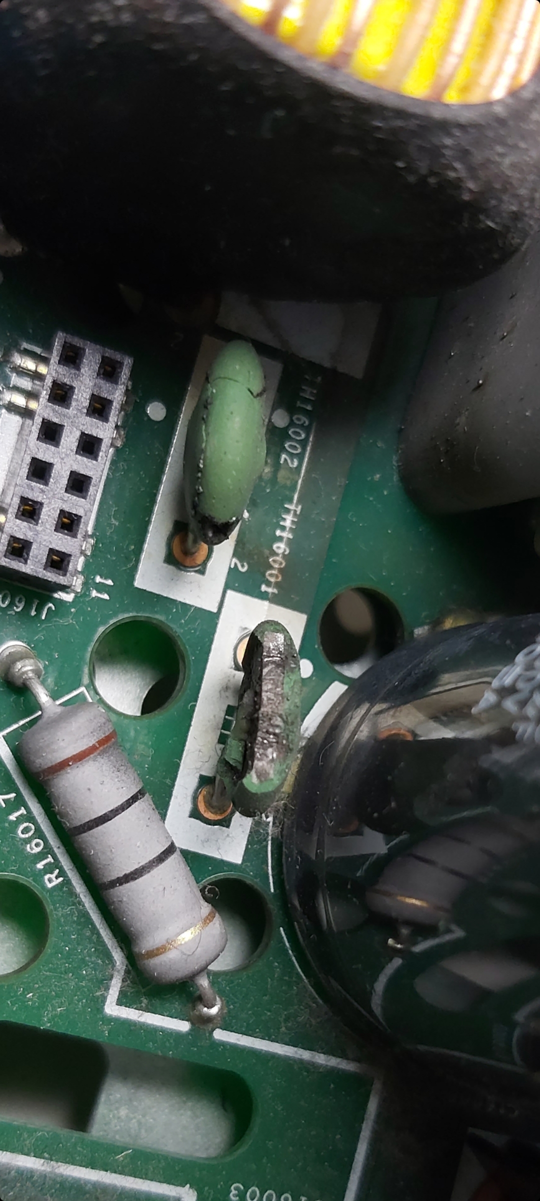
Hello, im from Germany and need your Help.
These two capacitors are defective. do you know the data for these?
TH16001 and TH16002.
Thank You
Max

- Contributor I
- October 3, 2021
Hi Max. Those are both NTC thermistors (not capacitors). They can be replaced with part # SCK-054.
They act as 5 ohm resistors at room temperature. As they warm up, their resistance drops. This prevents a large amount of current inrush at power up.
In a pinch, you could try replacing them with jumpers, but I would only do that if you are powering the board with a dim-bulb (as described earlier in this message thread). In that case, the incandescent light bulb will limit inrush current.
- Lyricist II
- October 3, 2021
Hi Tim, thank you. I have now ordered two of them. Can I destroy them by changing the AC voltage from 230V to 115V on the 230V grid?
- Contributor I
- October 3, 2021
Hi Tim, thank you. I have now ordered two of them. Can I destroy them by changing the AC voltage from 230V to 115V on the 230V grid?
Yes that could cause a lot of damage. The usual rectification generates the input times the square root of 2 as DC voltage. SO 115V input translates to about 162V. The switch on the back adds a voltage doubler to the rectifier circuitry. With a 115V input, that produces 320V internally, which drives the high voltage circuitry. If 115V is selected but the input is 230V, then it would internally generate 640V DC. That could break a lot of things. All of the power passes through the thermistors, and they blew up in protest of the voltage. The question is if they went before anything else ‘downstream’ died or not. It is possible that there was also damage to the PWM chip. This is the four pin device on a heatsink next to the transformer. You can check if it’s pins are shorted or not. If there are short circuits between pins then it is dead. If there are no shorts, it doesn’t mean that it isn’t broken though.
- Lyricist II
- October 9, 2021
Hello, I replaced the components and it works again. Thanks very much
- Contributor I
- November 11, 2021
I have no idea what kind of solder that Sonos uses, but it is insane. In order to get it to melt, I had to get my Hakko iron up to 900 degrees. 700 (its default) would barely get it to melt. Getting it off components was a chore. That PWM and heat sink took a good 45 minutes to get off along with about 2 feet of desoldering braid. I am surprised I didn't destroy contacts as I really had to put that iron on for a while to get that solder to move. I tried a desoldering pen too, but to no avail. The best way to get it off was keep cracking at it with desoldering braid. I would love to hear if anyone has any hacks or ways to deal with such a problem. ...
🙂
- The solder was no doubt lead-free, which has a much higher melting temperature than lead-content solder. The solder that is touched directly by the iron will melt but due to temperature drop further away from the iron, some solid solder will remain. Use a solder sucker to get as much solder off the joint as possible. There will probably be some solder remaining in hidden areas which makes it impossible to pull the component out. The heat from the solder iron does not get conducted to those hidden remnants of lead-free solder; so add some leaded solder* to the joint and let it flow in. The leaded solder will mix with the lead free solder and alter the alloy to lower the melting temperature. The added solder provides a better heat conduction path. Suck it clean again. Repeat a few times if needed.
Apply the iron to the component lead, not to the pcb pad. The copper clad of the pc board will peel away from the fiberglass if it get heated too much.
*Rosin core solder can get messy, and the rosin flux is not really needed since the copper has already been tinned. Find a spool of lead solder without a flux filled center in the plumbing department.
- Lyricist III
- November 14, 2021
I hope someone in this thread can help me as it’s been a while since this thread was created. I have a ZP120 from a friend of mine. I opened it up and immediately saw the blue 10 ohm 2W resistor was blown near the pwm (I think it’s called) with the black heatsink attached to it. I replaced both of these components as I thought the resistor had blown due to the pwm being bad. After replacing these components, the resistor blew again after 30 seconds or so. Anyone has an idea on where the short could be? I also removed the clips of the transistors and the diodes to their heatsinks and those show a small sign of black burn marks.
- Contributor I
- November 15, 2021
I hope someone in this thread can help me as it’s been a while since this thread was created. I have a ZP120 from a friend of mine. I opened it up and immediately saw the blue 10 ohm 2W resistor was blown near the pwm (I think it’s called) with the black heatsink attached to it. I replaced both of these components as I thought the resistor had blown due to the pwm being bad. After replacing these components, the resistor blew again after 30 seconds or so. Anyone has an idea on where the short could be? I also removed the clips of the transistors and the diodes to their heatsinks and those show a small sign of black burn marks.
I’ve fixed a lot of the zp120, but this is one that I don’t know of a definitive fix for, and I haven’t been 100% successful trying to fix it. 90% of the time, when there is a blown 10ohm resistor, just replacing it gets the device working again. Similarly, replacing a bad PWM usually does the trick.
You should look at info earlier in this thread (or just google it) for how to build a dim bulb tester. This has a huge advantage in this kind of case. On a broken device, the bulb will glow brightly, but it won’t dim back as it should (once the power supply capacitors are charged). It serves to limit current, and will prevent more components from failing every time you test something. Without this, you may end up replacing the 10 ohm and pwm multiple times.
You can check the PWM device by testing each pair of pins using a diode tester (test in both directions). You should get either infinite or ~ 0.6V between pins. If you get a 0V reading between two pins, your PWM is bad again.
If you remove the PWM, try powering up the device without it. If it doesn’t draw a ton of current (ie: the dim bulb goes out), then that confirms that the problem is ‘downstream’ of the PWM.
Check the transformer. There are 5 pins on each of the primary and secondary sides. They are organized as one group of 3 with a centre tap, and a separate (isolated) group of 2. That makes 4 separate windings on the same core. You should get low resistance across each coil within each winding, but no continuity between any two different coils. If you find continuity between two different coils, then you have a short (hope that makes sense). Also, with a good multimeter, you should find 0.1 or 0.2 ohms when measuring a coil. If you get 0 ohms, then you may have a short within a coil.
Here is a less likely bit that you can check which is easy to check… There are 4 largeish surface mount diodes near one of the corners of the board on the underside (across from the power input). Check these 4 to see if any have failed using a diode tester. (You can do it in circuit) I don’t think it would cause your issue, but these do go fairly often in my experience.
Enter your E-mail address. We'll send you an e-mail with instructions to reset your password.