
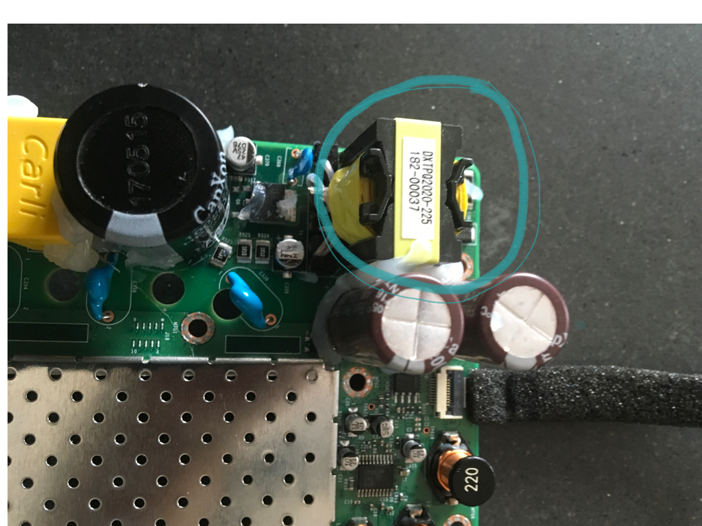
Hello, last week Ive found my Sonos 1 without any light, so I started to troubleshoot and the yellow part in the picture is damaged, plastic and wires are cuts.
DXTPQ2020-225, didnt find any parts info for replacement, any idea ?
Thanks
This topic has been closed for further comments. You can use the search bar to find a similar topic, or create a new one by clicking Create Topic at the top of the page.
Hello, last week Ive found my Sonos 1 without any light, so I started to troubleshoot and the yellow part in the picture is damaged, plastic and wires are cuts.
DXTPQ2020-225, didnt find any parts info for replacement, any idea ?
Thanks
I have a dead Play1, and I think the transformer may be bad. How did you determine that yours was broken?
I find about 155VDC on the primary (yes, DC - I presume that when it's working, it is cycled via the opto-isolator), but 0V on the secondary side. I don't have continuity across the primary coil, which is why I think I have a problem transformer.
Did anyone ever find a replacement?
I guess that I can take apart another (working) Play1, and try to determine the characteristics of the transformer, but that's not ideal for obvious reasons.
Thanks,
Tim
Does anyone know where i can find a detailed list of all the parts on the play1 motherboard?
It doesn't exist. There are no authorized repair services -- the only 'sanctioned' way to get a device repaired is to return it to Sonos. As a result, Sonos has never provided any repair guides or parts lists.
[quote=timc995]Hello, last week Ive found my Sonos 1 without any light, so I started to troubleshoot and the yellow part in the picture is damaged, plastic and wires are cuts.
DXTPQ2020-225, didnt find any parts info for replacement, any idea ?
Thanks
I have a dead Play1, and I think the transformer may be bad. How did you determine that yours was broken?
I find about 155VDC on the primary (yes, DC - I presume that when it's working, it is cycled via the opto-isolator), but 0V on the secondary side. I don't have continuity across the primary coil, which is why I think I have a problem transformer.
Did anyone ever find a replacement?
I guess that I can take apart another (working) Play1, and try to determine the characteristics of the transformer, but that's not ideal for obvious reasons.
Thanks,
Tim
I FIXED my dead play1. :D
I removed the bad transformer. From a good play1, I determined that the transformer was converting 155 VIN to (I think) 18V, which was then converted to 24VDC on the board. There are hundreds of transformers on mouser, but rather than try to find a replacement and then wedge that into the space, I went another route. Using my bench power supply, I was able to feed 24VDC in to the board and everything worked. I measured a peak draw of about 350mA, which works out to about 8 watts. I then purchased an AC/DC power module. This was mouser part 709-30-24ST (they also have 709-30-24, but that has pins instead of screw terminals). It was a mean-well IRM-30-24ST "ac/dc power module 31.2WQ 24V 1.3A Screw terminal style". I chose a 30W unit just to be safe. You may be able to use a smaller rated unit, but I figured that this would fit the space, and it was pretty inexpensive (about $15USD).
By feeding connecting the inputs of this to the 155V pins from the transformer primary side (the outermost 2 of the 6 provided on the board), and connecting the 24VDC output to the two 24V storage capacitors, the device worked great. My next challenge was to get it all back into the enclosure. I was able to gently bend the speaker terminals out of the way, and put the module right behind the tweeter. However, the two tall storage capacitors needed to be moved to allow me to put the control board back in place. I removed them and laid them flat against the board. I taped in place with tuck tape (which is very tolerant of temperature swings and does not dry out). I wired the capacitors in series and reconnected them to one of the formerly occupied pairs of through holes. I then wired the 24VDC module output to the other pair of through holes. I also included several layers of foam insulation to make sure that there would be no vibrations caused from within the enclosure due to vibration of either then new module or the repositioned capacitors.
It's been running for a week with no issues. Some pictures are attached.
I hope that this helps others with similar problems!
I fixed mine today! It lost power about a week ago. We had a power surge and my kitchen cabinet lights went also. There’s a decent video on YouTube that explains how to dismantle the Sonos 1 Play. I found the fuse and replaced it, put it back together and it works again. I’m no expert and this is the first time I’ve ever done this but I saved over £100 of repairs so I am well pleased. The fuse is T2A Antisurge 2A 250V and cost £2.44 for 3. I was able to borrow a soldering iron so was lucky in than respect.
In my case, the TH301 thermistor had burnt even without any problem in my electrical installation. One or two days before my Play:1 went dead, its back side was getting extremely hot.
I’m not shure, but I guess the failure had something to do with the fact that for 4½ years, I always powered it off by a single pole switch, when not listening to it. Maybe power peaks at each startup wore out the TH301.
And MOV301 didn’t look very well neither.
After replacing both of them, my Play:1 works well again, and stays much cooler at the back side.
Hello, good people. Im a little desperate. Bathroom humidity completely destroyed my Sonos One top control board and flex cable. Logic board is surprisingly works, I even still able to listen to music with it.
Does anybody knows a source for spare parts? Or, maybe has such parts for sale? Ebay has been no luck for quite some time...
Thank you!
I have just opened I to find the same problem. The 2 burnt components in Lazarov’s pics are 1 Ohm 1/2w 1% 1206 smd resistors, (here’s another just above them)
You will also find the black square component next to them (Q6) is a SPD03N60C3BTMA1N 3.2A 650V MosFet which will be shorted, also check R517 resistor next to the right hand leg should be 100R resistor which comes from pin 8 (Gate Drive)of the IC on the bottom side marked 6751MR (FAN6751MR), the bridge rectifier DF1506S-T (1.5A 650V) and lastly the fuse near the AC i/p connector (2A 152V)