Hi
Play:5, manufacturing date sometime around 2009, is completely dead. No light in LED.
Found several cases of this online, but no solutions.
Does anyone have any knowledge about the problem, og better yet, schematics..
I mainly suspect problem in switch mode power supply. Have only done very basic measuring, but I find 220VAC on primary side, no power on secondary side. I think about ordering a mosfet, and/or a diode I suspect, but if I had schematics I could do some more pinpointing..

This topic has been closed for further comments. You can use the search bar to find a similar topic, or create a new one by clicking Create Topic at the top of the page.
Page 2 / 9

Hi,
how much power needs play5? I found a power supply. If it is fits (physical and electrical) I will buy and install it.
Size: 16 * 10 * 4cm
Can you tell me which pins should I connect 24 and 12 volt in play5 mainboard?
This one is at amazon.de 14€, I think it is fair price.
That power supply looks like it should work. I don’t know what the maximum rated power of the Play:5 is, but that one looks like 70 Watts… For me that’s more than enough volume.
As far as connections… There is a triple inductor between the power supply and the downstream electronics. The purpose of that inductor is to filter noise. You could hook up to either side of the inductor (since your power supply will have filtering in it), but I would hook up to the inductor on the power supply side. This way, the outputs from your supply will pass through the inductor and be filtered. I’ve annotated the 12V, GND, and 24V in the attached image.
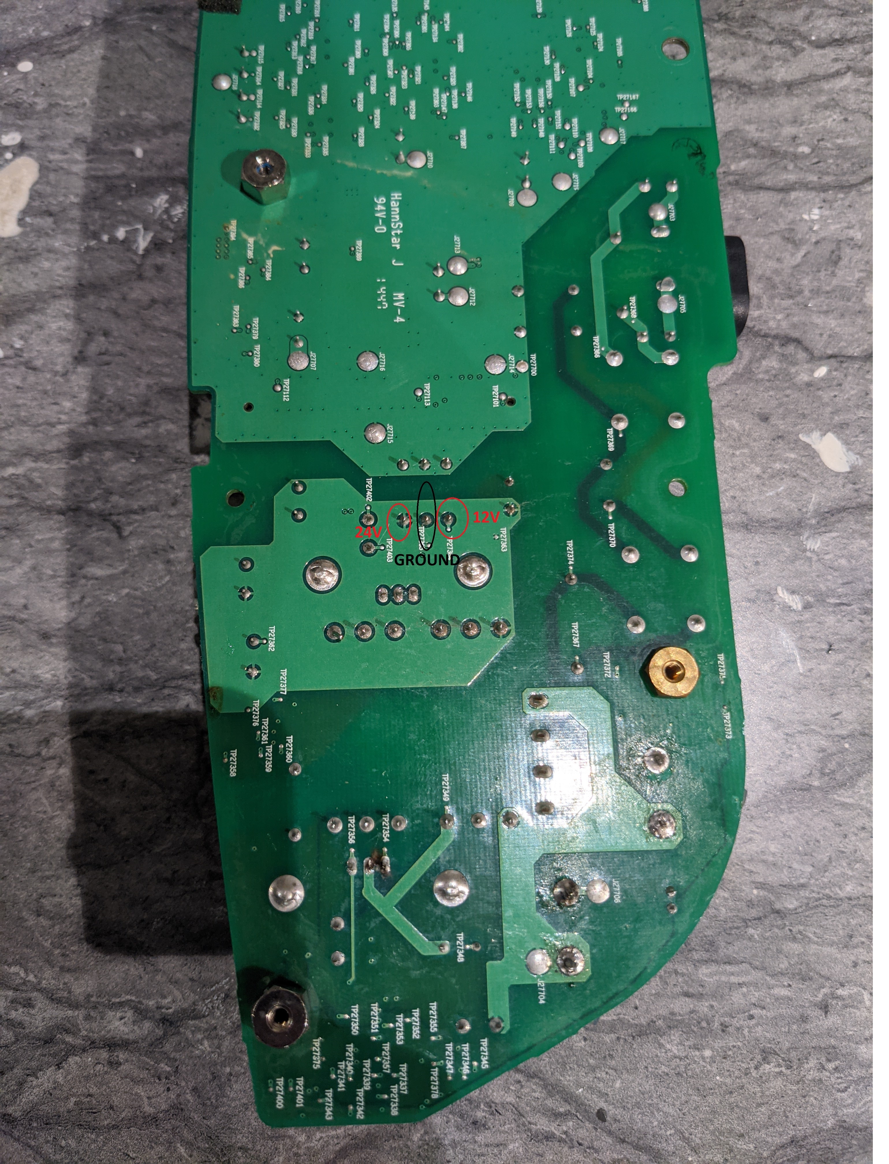
There is a small chance that the problem with the power supply circuit will prevent just adding power to the board. In this case, you would need to separate the built-in power supply from the downstream components. I would do that by just removing the inductor (desolder it, or cut the legs of it off and remove it). If you do this, then you will need to connect to the three connection points directly above the ones that I marked (the order is the same as I labelled).
Good luck!
E48 9558 or something like this.
It is blurred, so i cannot read ut as well.
Can someone help me and can tell me, what part it is?
It looks to me like it is “E43” and 955B or maybe 95513… that last bit doesn’t really seem to be a B or a 13, but it looks even less like an 8 to me.
Having said that, I’d be a bit surprised to find a 170 volt zener diode in this circuit…

Hi,
I have a new problem with my play 5.
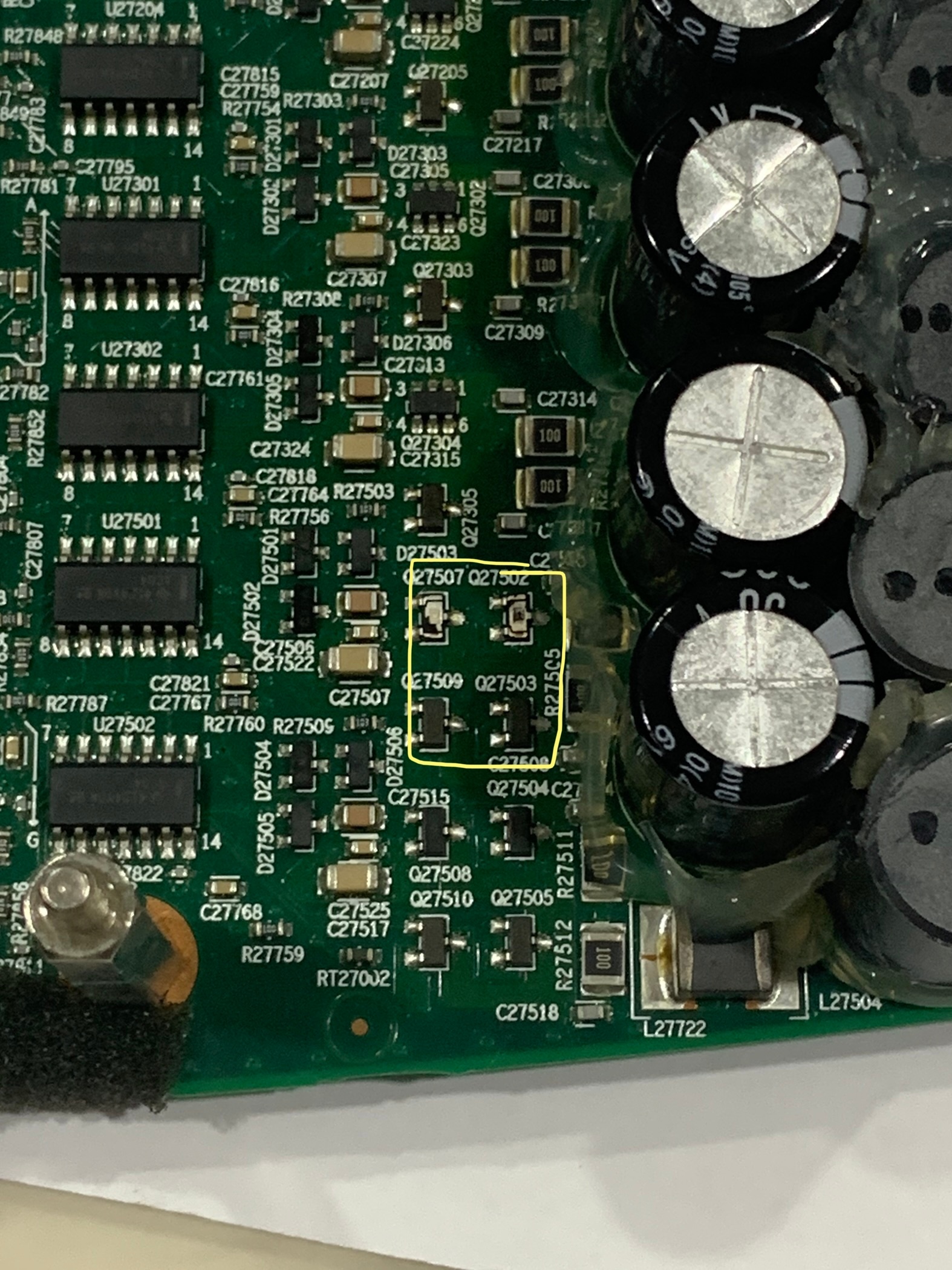
2 components were blown Q27507/Q27502.
2 components shorted, Q27509/27503.
I think the part numbers are 34N B1. What are these? Mosfet? Appreciate it if anyone can share the part numbers of that 4 components in yellow box. Thks!!
 +1
+1
And can someone tell me, what size of smd resistors they are, I can't measure up this size
Hi guys,
can someone tell me, what parts are the following and what I need to replace?
R27817
C27852
C27855
They are burned.
100ohm
0.1nF(maybe)
2.9nF(maybe)
So what does it mean "maybe"? Can't I measure up an SMD capacitor or what?
For what it’s worth, I tried measuring these in circuit with my Fluke 87V. I got 0 for C27852, and 2.0nF for C27855. I imagine that the 0nF reading is due to the measurement being done in circuit.
Anything with this low a capacitance is going to be a filter cap, and I’m pretty sure you can just go with a low value (or maybe even no capacitor) and it would be fine. I had a look at the eval board application note, and I don’t even see these caps in that circuit diagram https://www.infineon.com/dgdl/Infineon-ApplicationNote_EvaluationBoard_80W_SMPS_QR_PWM_Controller_ICE2QS02G%20-AN-v01_00-EN.pdf?fileId=db3a30431a5c32f2011abefae1533bcd
Hi there,
I have the same problems (sorry for my bad english). One of the 120K smd resistors was defect, i place a new one but nothing happens.
On the 2 big elcos i measure 319 vdc but the little one of100uF is charging up to 19v en then back to 5v and thats repeating. When i measure with my scope i see the elco is charge and then recharge. I also replaced the 8p ic on the prim side. I checked al the components on the primair side but nothings wrong??
+1
Ok I understand. So you mean that I could only use one capacitor with 2 or 3nf instead of the 2 SMD capacitors?
I’ve just been repairing one of these, using many of the tips here. Some observations for those following in the footsteps of many:
I had a blown fuse, then needed to track down what else was faulty. Replaced fuse with same type. I thought the DC measurements were suggesting a problem with the MOSFET switch, so I changed that out with another N-Channel of similar value I had on hand. The Dim Bulb Tester indicated there was still something wrong, but interestingly I was getting some useful DC voltages. My DC measurements of the bridge rectifier didn’t suggest it was faulty, so I pressed on. Decided to try plugging directly in to the mains. Big mistake. Loud explosion as the fuse self-destructed.
So stepping back I decided to use a process of elimination. I removed both 100uF charge capacitors. Replaced fuse, connected Dim Bulb Tester, still showed excess current. I then removed the bride rectifier and replaced with another I had on hand. Success: no more large current drain.
I intend changing out the 100UF caps with high quality brand, as well as the electro caps on the cold side.
But this failure of the bridge rectifier is a weird one. I fix Switched Mode Power Supplies a fair bit. Bridge rectifiers either go short or open circuit. It’s as if this is failing under mains voltage?
Anyway, that bridge rectifier is a bugger to get out. Removing the two 100uF caps gave better access to be able leverage it out whilst hitting it with the soldering iron (after having previously used a desoldering gun on those terminals).
+1
I look all the time for the spare part, I've also looked at another box of mine, it says "E43 955B". So apparently this 955B is a kind of article number. And when I look at these numbers and add onsemi as the manufacturer, according to their products I always come to 1SMB5955B, with the first 5 probably indicating the tolerance.I don't know a lot about electronics and their spare parts.Am I doing something wrong with my search or what would happen if I put this part in and it's the wrong one?
Great, i will try to measure the voltage and see if the result could guide me.
Short circuit Player 5.
Dr Phil, your latest Post. Sorry I can’t find a “New Post” button on this page. Have to ride on yours.
Dead Player 5. Blown fuse. Installed larger fuse - tripped kitchen supply. Tested 8ohms across mains input. De-soldered/pulled one leg of the 2nd right-hand green filter coil (facing mains plug). Short cct now moved to bridge-rectifier. Meaning: replace the blown fuse but don’t waste time checking onward components to rectifier. It’s the 4-pin big black rectangular bastard behind the fat capacitor to the right.
Do not be dissuaded, have patients. Detach hot-glued components with drips of Isopropyl Alcohol bit by bit with screwdriver, easy-peasy. Firstly remove fat capacitor (notice white -ve polarity position). Second: the 4 rectifier legs. High class Sonos pcb (board) needs high temp narrow soldering iron bit. De-soldering braid and solder flux if you have it. Medium screwdriver leverage of component against board.
Yes, ESR tested both fat caps OK. Others too. Gonna replace bridge rectifier and fat caps. Awaiting delivery. And Comments / advice.
+1
What part is the Oscillator?
Userlevel 7
 +23
+23
For me, both mids and highs were also without function. I replaced all the capacitors, after that no more problems.
Ahh if only it were that simple for me. While indeed the caps may be also an issue…..there are so many other blown components on the board 😌
How about buying a “for parts only” P5 as usually its the power supply that fails, and swap the amp board from that into this one?
Short-circuit Player 5
Dead Player 5. Blown fuse. Installed larger fuse - tripped kitchen power supply. Tested 8ohms across mains input. De-soldered/pulled one leg of the 2nd right-hand green filter coil (facing mains plug). Short cct now moved to bridge-rectifier. Meaning: replace the blown fuse (small brown cylinder behind power input socket) but don’t waste time checking onward components to rectifier. It’s the 4-pin big black rectangular bastard behind first fat capacitor to the right of power input socket.
Do not be dissuaded, have patients. Detach hot-glue from components with drips of Isopropyl Alcohol bit-by-bit with screwdriver, easy-peasy. Firstly remove fat capacitor (notice white -ve polarity position). Second: the 4 rectifier legs. High class Sonos pcb (board) needs high temp narrow soldering iron bit.
Use de-soldering braid and solder flux if you have it. Medium screwdriver leverage of component against board.
Yes, ESR tested both fat caps OK. Others too. Gonna replace bridge rectifier and fat caps. Awaiting delivery and, your Comments / advice.
I look all the time for the spare part, I've also looked at another box of mine, it says "E43 955B". So apparently this 955B is a kind of article number. And when I look at these numbers and add onsemi as the manufacturer, according to their products I always come to 1SMB5955B, with the first 5 probably indicating the tolerance.I don't know a lot about electronics and their spare parts.Am I doing something wrong with my search or what would happen if I put this part in and it's the wrong one?
That matches the labelling I had found, so I guess it is the right part.
How do you actually know it’s broken? It can be hard to confirm bad components when in circuit. You might want to try removing it and then check it for continuity, and test using diode mode on your meter in both directions.
Hi,
I have a new problem with my play 5.
2 components were blown Q27507/Q27502.
2 components shorted, Q27509/27503.
I think the part numbers are 34N B1. What are these? Mosfet? Appreciate it if anyone can share the part numbers of that 4 components in yellow box. Thks!
On my board, all 4 of those components are the same, and are labelled DMB B8. That is a DMP3098L (P-CHANNEL ENHANCEMENT MODE MOSFET https://www.alldatasheet.com/datasheet-pdf/pdf/405103/DIODES/DMP3098L.html?)
The really weird part though is that “34N” is a different device! That’s an N-channel mosfet: https://www.diodes.com/assets/Datasheets/ds31787.pdf
Good luck!
Thanks Tim. You are truly helpful. Looking thru the datasheet, the Q27509/Q27503 on my board is indeed 34N B1, same marking placement as well. I am guessing those 2 blown would be the same.
Looking at my board again, only Q27515/Q27504 are labeled as DMB AN.
The rest like Q27203/Q27205/Q27303/Q27205 are all 34N B1
Fingers cross, thanks.
Hi,
Thought I would add some information to this thread since it helped me resurrect a dead play 5 gen 1.
A few months ago my father informed me that one of his two play 5 speakers was completely dead. After browsing the internet we found that the fuse and rectifier could be possible causes. We opened the speaker and found that fuse was still intact. Some more browsing led us to this thread with other possible causes for a dead speaker. None of the earlier mentioned resistors etc. seemed to be the issue in our unit. Then after randomly measuring resistors with a multimeter I found R27793 near one of the big capacitors being open. 1203 is printed on the resistor and according to this page that means 120 kΩ.
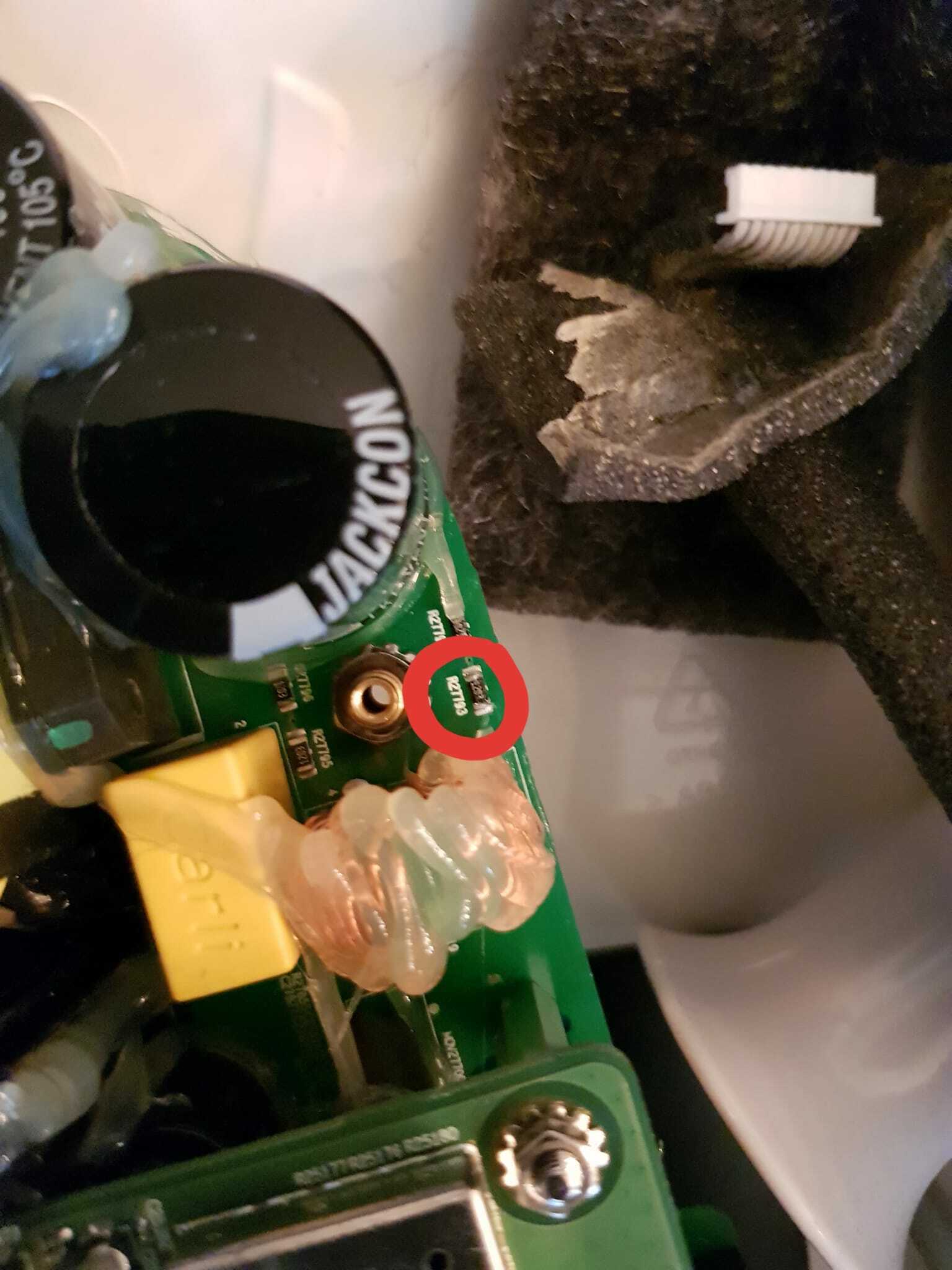
A new 120 kΩ resistor was then soldered to the board and now the speaker is working again. ![]()
Hopefully this can be of some help if someone else would have the same issue. ![]()
I get a range of voltages supplied to the PWM chip from 9-20V. Oscillating at roughly a 4 second frequency.
There are few examples in this thread about finding various broken components, where replacing/repairing them fix similar symptoms to what you have. However, I have seen some bad Play:5 boards that I was never able to find the bad component and was unable to fix.
I’d recommend replacing the power supply. It’s pretty cheap to install a 24v DC power supply (either external, or inside the case if you can get one to fit). You would need a 24V->12V converter to provide the 12V supply too. All of this is probably under $30. This is described on this forum (I think in this thread but not certain).
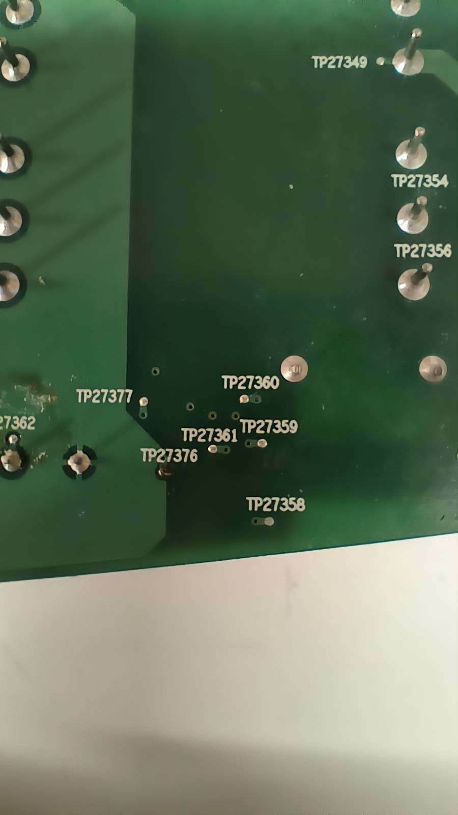
Again, this only works if it's resistor R27842 that's dead. You can verify this by putting your ohmmeter between TP27376 and TP27377. I was seeing an open circuit there. I soldered my new 1,000 ohm resistor between those two points. I left it laying flat against the board to leave plenty of room when putting everything back together.
Good luck!
Hi,
I have a new problem with my play 5.
2 components were blown Q27507/Q27502.
2 components shorted, Q27509/27503.
I think the part numbers are 34N B1. What are these? Mosfet? Appreciate it if anyone can share the part numbers of that 4 components in yellow box. Thks!
On my board, all 4 of those components are the same, and are labelled DMB B8. That is a DMP3098L (P-CHANNEL ENHANCEMENT MODE MOSFET https://www.alldatasheet.com/datasheet-pdf/pdf/405103/DIODES/DMP3098L.html?)
The really weird part though is that “34N” is a different device! That’s an N-channel mosfet: https://www.diodes.com/assets/Datasheets/ds31787.pdf
Good luck!
Thanks Tim. You are truly helpful. Looking thru the datasheet, the Q27509/Q27503 on my board is indeed 34N B1, same marking placement as well. I am guessing those 2 blown would be the same.
Looking at my board again, only Q27515/Q27504 are labeled as DMB AN.
The rest like Q27203/Q27205/Q27303/Q27205 are all 34N B1
Fingers cross, thanks.
I opened up another PLay:5.
The two on the right are 34n, and the two on the left are DMB. When I read the first board, I had confirmation bias as I was expecting to see DMB, and I was looking through a bunch of glue residue. Those are indeed 34N as well.
This actually makes a lot of sense -- there should be both N and P channel to drive the speaker.
Sorry I misled you. I hope you see this before ordering parts!
Thank you
Thanks Tim. I have not order the parts yet. 😀 will place an order for both 34N and DMB. Cheers!!
Hi all
im gunna jump on this thread and ask for some from all you fellow fixerupers
my play had a blown fuse and rectifier which i replaced. however its still dead. i have measured around the board but im not 100% what im looking for.
so the big ass caps have 86 volts across them. the ac pind of the rectifier has 90 + volts
is there any test point i should be looking for that anyone knows of?
thanks all in advance
theres also high possibility i have broke somthing replacing that rectifier. is there any test points i can test to between the rectifier and wherever.
thanks again
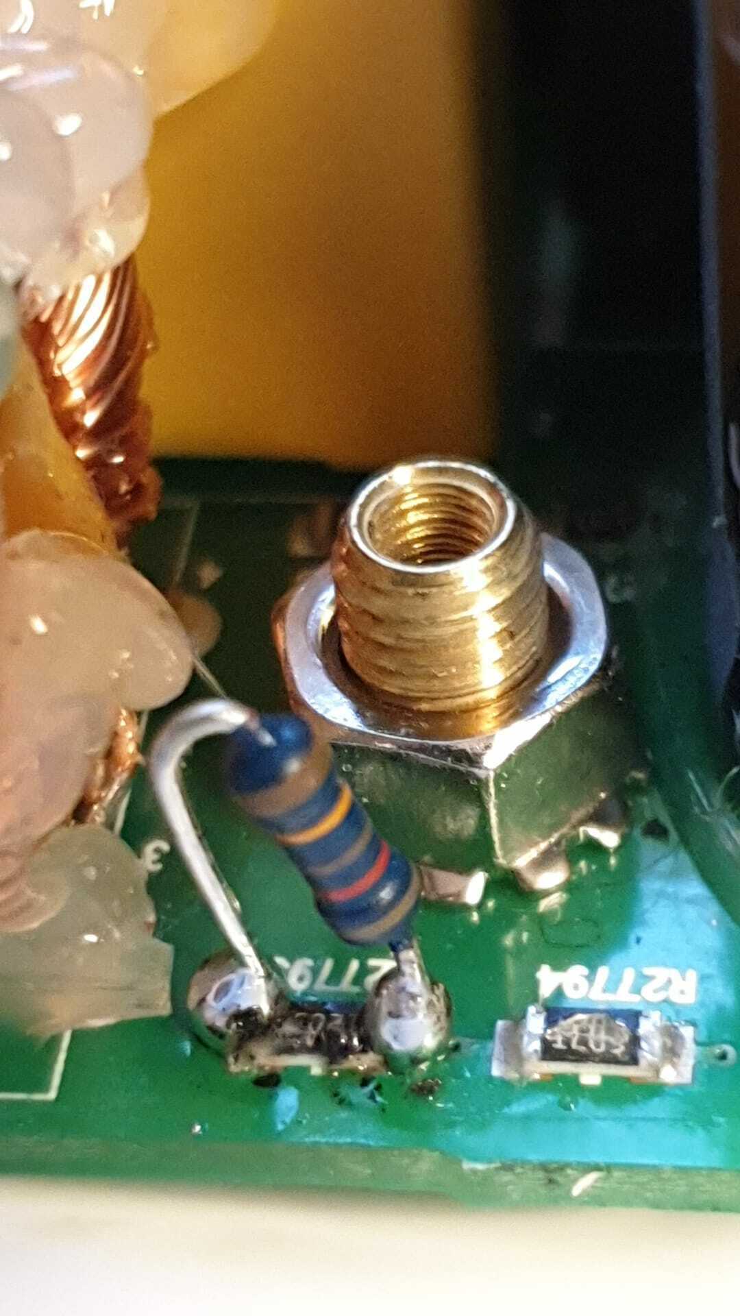
Can someone tell me the value of resistor R27842? Looks like it starts with “01..” but can’t be sure and I definitely can’t make out the last digit. It’s reading open. I think I scraped off some of the markings trying to get the glue off of it.
R27842 - 01b - 1kohm - 1000 ohm
Hello, thanks for the picture.
I have-it fixed finally but I do not know the cause. Here it is in words and pictures:
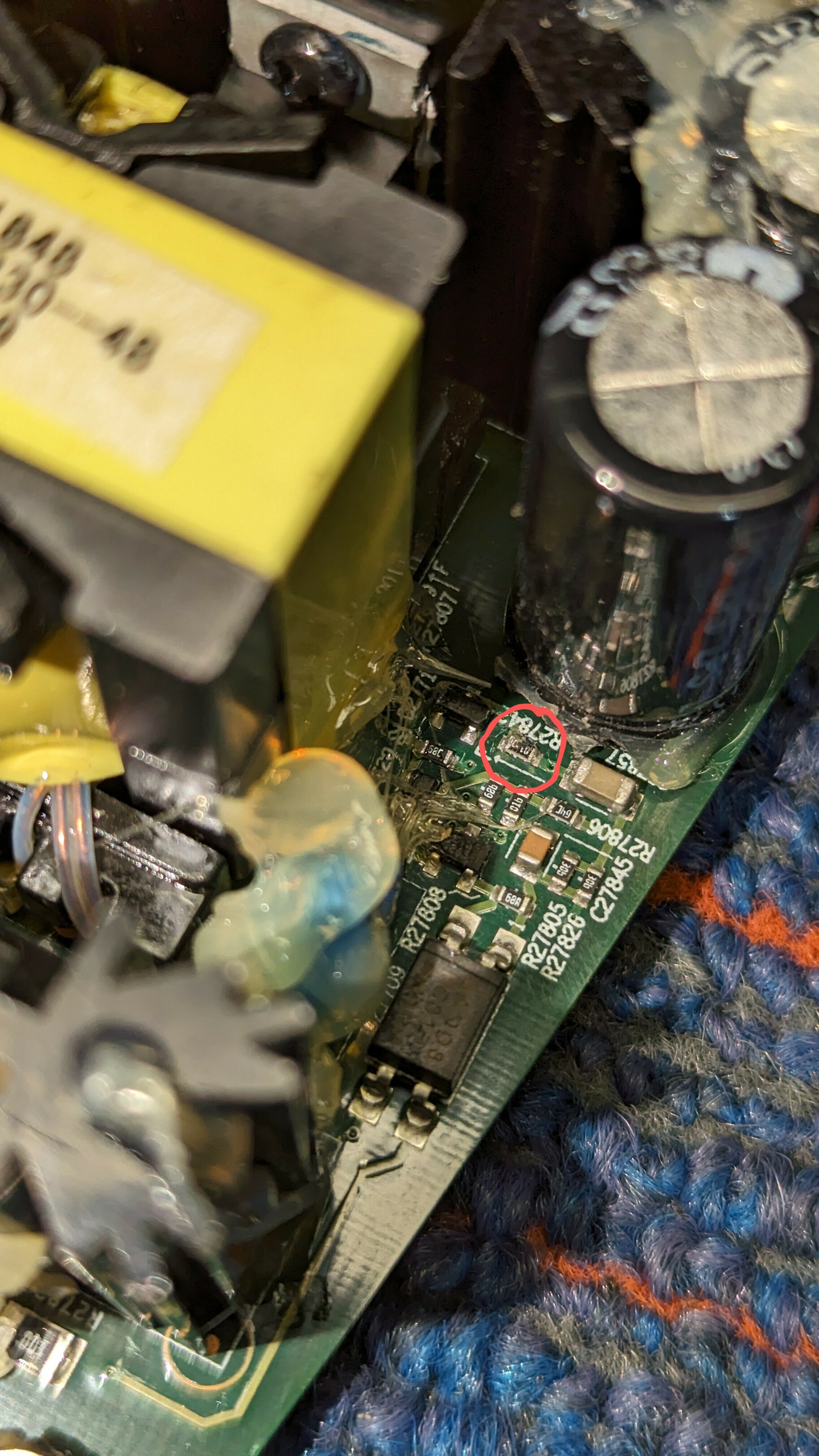
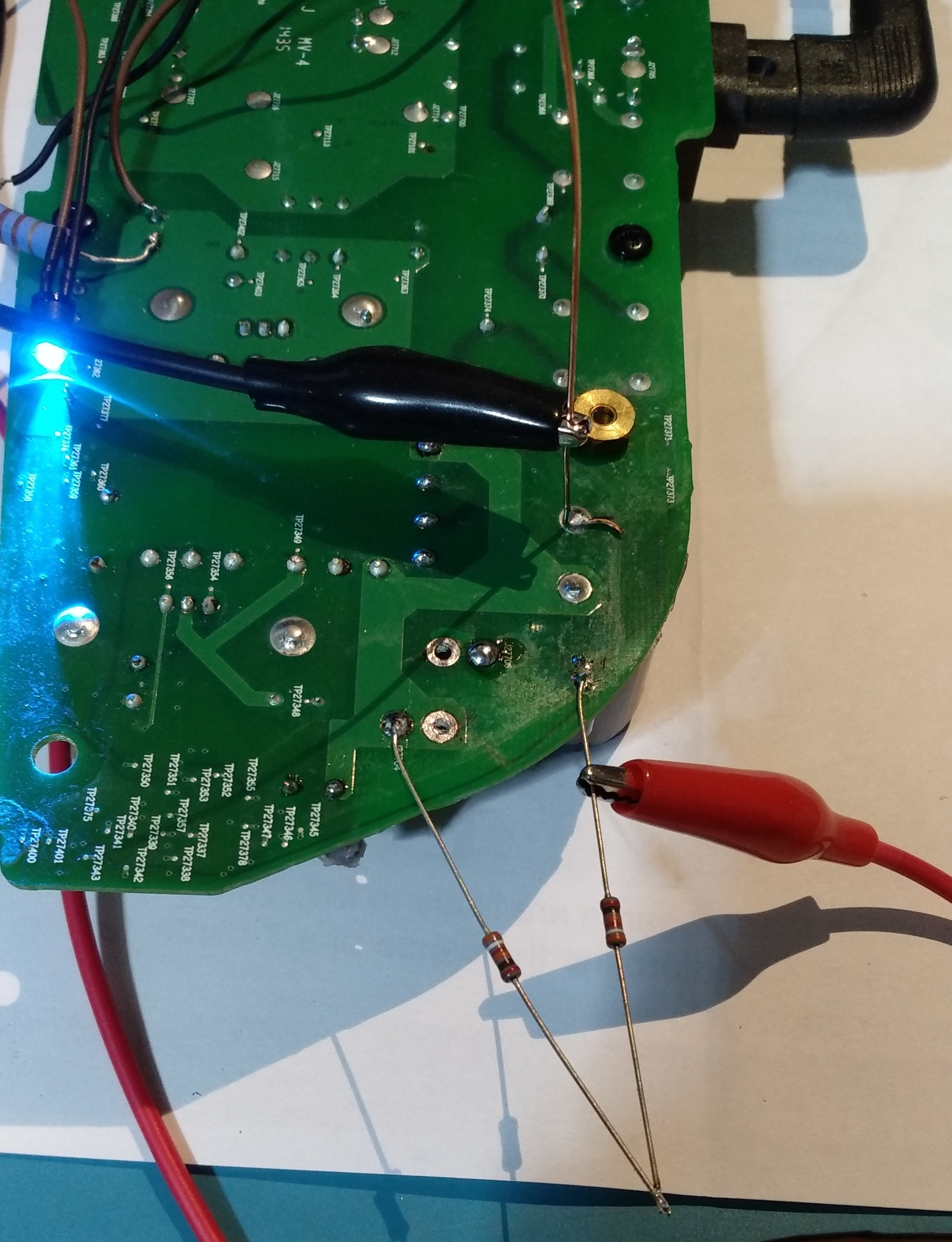
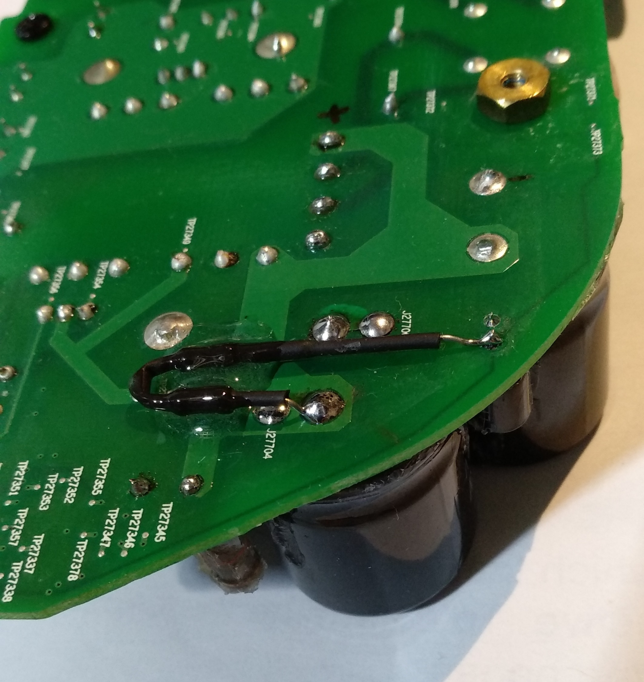
First, small cap (C27854) is not charging from the AC side, those are probably discharge resistors to the remaining capacity in the filtering caps. It’s another mechanism I could not figure out. The C27854 is providing power to the ICE2QS02 driver chip. It goes thru all those small diodes and caps on the edge of the board. The normal behavior on the voltage for C27854 is that is charging up to around 20V slowly and then ( some of those diodes and transistors do that) turns on the power on the ICE2QS02.
Once the chip is starting the voltage is self sustaining to around 13 V, I do not understand from where, maybe from the fly back transformer winding itself.
So for me the challenge was to produce the charging of the C27854 up to 20 to start up the IC. I did this by putting 2 390Kohm from the + on the big caps. I monitor the voltage and it’s ramping up slow, like a second or two. After it reaches 20V the IC starts and it self sustain to 13V. It’s 3 days already and still works! meaning there is no other fail. There was no problem in the fuse or rectifier, nothing burned. As you can see the LED turns on with the 2 resistors soldered. This is the story of this fix.
I have no power on pin 7 on ICE2QS02 and when i measure on C27854 it goes from 9 to 18 VDC in a 2-3 second loop, is this the same behaviour as you had?
Page 2 / 9
Enter your username or e-mail address. We'll send you an e-mail with instructions to reset your password.