Hi
Play:5, manufacturing date sometime around 2009, is completely dead. No light in LED.
Found several cases of this online, but no solutions.
Does anyone have any knowledge about the problem, og better yet, schematics..
I mainly suspect problem in switch mode power supply. Have only done very basic measuring, but I find 220VAC on primary side, no power on secondary side. I think about ordering a mosfet, and/or a diode I suspect, but if I had schematics I could do some more pinpointing..

This topic has been closed for further comments. You can use the search bar to find a similar topic, or create a new one by clicking Create Topic at the top of the page.
Page 5 / 9

A definite maybe.
- You need to worry about wattage as much as voltage. You would want to use a supply with enough wattage. 95% of music I play is not so loud that I can’t have a conversation around it… That kind of level would be fine with 20 watts. I just looked at a Lenovo laptop adapter. It is marked output 20V 2.25A. That works out to 20*2.25=45 watts (before anyone jumps in to say this isn’t right -- it’s close enough for this conversation). Most laptop adapters should have enough wattage to work
- Most amplifiers will operate with a range of input voltages. You may get clipping or dropouts if you try to turn the volume up to a point beyond what the power supply can manage. Below that level it would work ok. If something is designed to work with 24V, and you feed it 20V, then you can expect a maximum output wattage of about 70% of the designed output. (This is calculated as (20/24)^2 ).
- Sonos is not necessarily “most amplifiers”. I have done a ton of work with ZP120 repairs. Those operate with several internal voltages. In particular, the audio section works at about 15 volts, until you turn the volume up... then a 36 Volt circuit comes on. The ZP120 has a voltage sensing circuit in it, and if the 36V circuit does not activate properly, it reports an error and ramps the volume down to about 10%. My experience is that this circuit must be 36V -- not 30V and not even 40V.
- I don’t know if the Play:5 has the same kind of voltage detection as the ZP120 or not. I was once able to disable the voltage sensing circuit in a ZP120 and drive it with a different voltage, but it isn’t really a practical fix for the ZP120, let along the Play:5
So the upshot is that you won’t damage anything by hooking it to a 12V and 20V supply (instead of 12V and 24V). The worst is that it doesn’t work (but it won’t do any permanent damage)
Some more on wattage…
Sonos speaker wattages are not (as far as I know) published. It’s also hard to reverse engineer, since it is not driving 1 or two simple speakers. There are 5 separate amplifier circuits for the 5 speakers. I have measured the 5 speakers, and they seem to be 7 ohm tweeters, 3 ohm mids, and 3.6 ohm bass. There is also some crossover and equalizer circuitry. If I make some very coarse assumptions, then I calculate a maximum wattage of 200 Watts. Paring this back for crossovers, as well as frequency impedance curves, I’d be surprised if a 70 Watt supply wasn’t more than sufficient. (and if you’re using a 20 Volt supply, then apply the above 70%, and you’d be ok with a 50 watt adapter). This seems to me to be more than reasonable from another angle… when I look at the circuitry of the power supply, it ‘seems’ to match these kinds of numbers based on its physical size.
Hi guys,
can someone tell me, what parts are the following and what I need to replace?
R27817
C27852
C27855
They are burned.
100ohm
0.1nF(maybe)
2.9nF(maybe)
 +1
+1
How mich W must have the resistor or doesnt care?
It's just a damn psu.
Strange that none of you 'tronics boffins have risen to the challenge of reverse engineering the Play 5 psu schematics.
A hand-drawn scribbled diagram, that ain't gonna offend our masters. SONOS might even
appreciate the good-will benefit of allowing it in these pages. Otherwise we're all still buzzing around like flies circling meat in plastic film, cursing their product brand telling others to avoid it.
How mich W must have the resistor or doesnt care?
maybe 0.1w or below,i guess
Hello,
i have another Problem with my Play 5 Gen 1.
One of the Middle Speakers is Not working. I have buy the speaker as "completely dead", repared it and i dont know if the speaker is working before. Is there any idea what i habe to check? The rightmiddle speaker is Not working.
Hello,
My play 5 Gen 1 is acting a bit strange. when i power the speaker up it is working fine. when i restart (unplug an replug) the play 5, to move it for example. it won’t boot up. no lights no sound.
if i wait a couple hours it will boot up again. can this be a capacitor fault or a thermistor somewhere?
I desoldered all the capacitors and measured them, they seem te be okay. (capacity measurement only, no ESR)
my voltages are similar to Anders J. Instead of 0V i get between 0-2 volts which should be 11-12 and 24V. so i think the problem should be somewhere on the HV side.
Since the speaker wont turn on for a while could this mean the capacitors have to be empty first?
(picture from Anders J.)
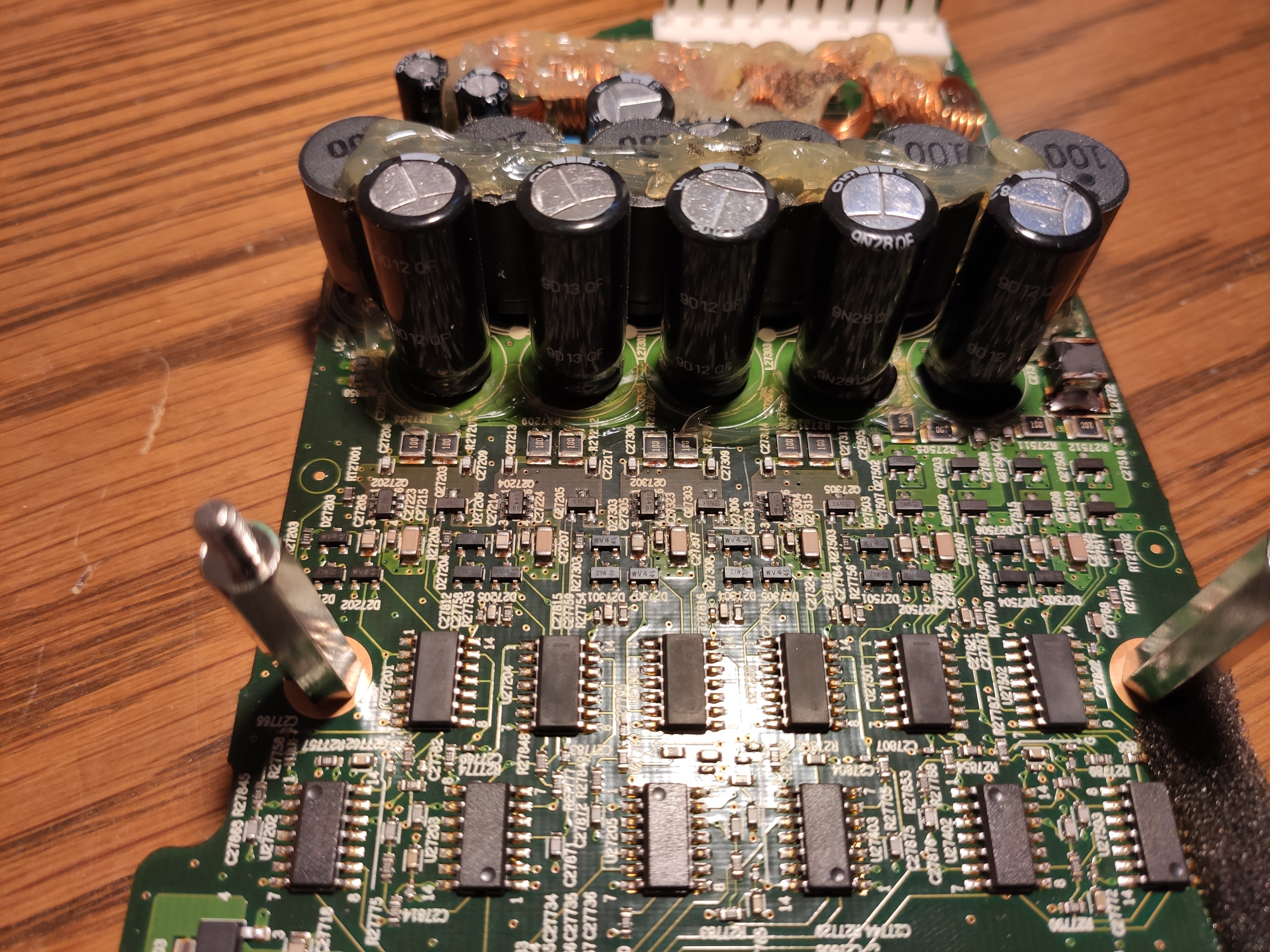
Hi, First post here and I’m asking for help with my Play 5 1gen. Bought used and claimed to be working. It powers up fine and connects to WiFi, also streams music fine, so power supply and networking components all working. Problem is both the left and right mids have gone and bass sounds questionable. Now in opening it up it has been worked on before, I can see older style resistors added and think bridge rectifier replaced. There is clear evidence that the main amplifier capacitors have been looked at...probably de-soldered and tested and refitted, this is judging by the flux stains on the back of the board. So I’m assuming speaker failed for power supply issue but when that was fixed the sound issue was discovered, capacitors checked but no solution found.
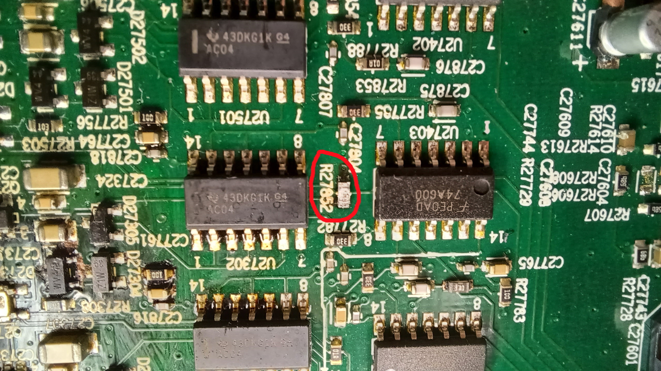
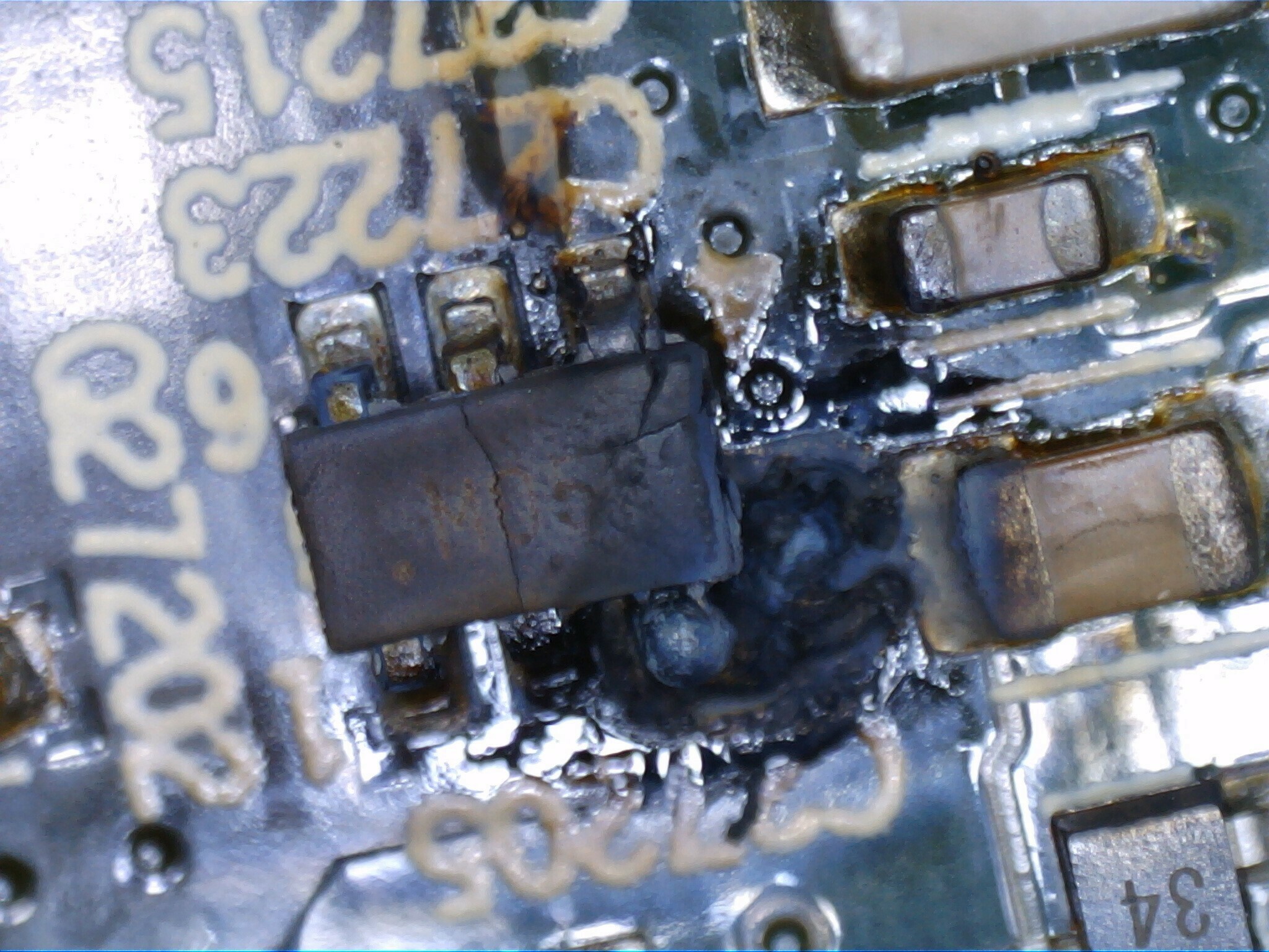
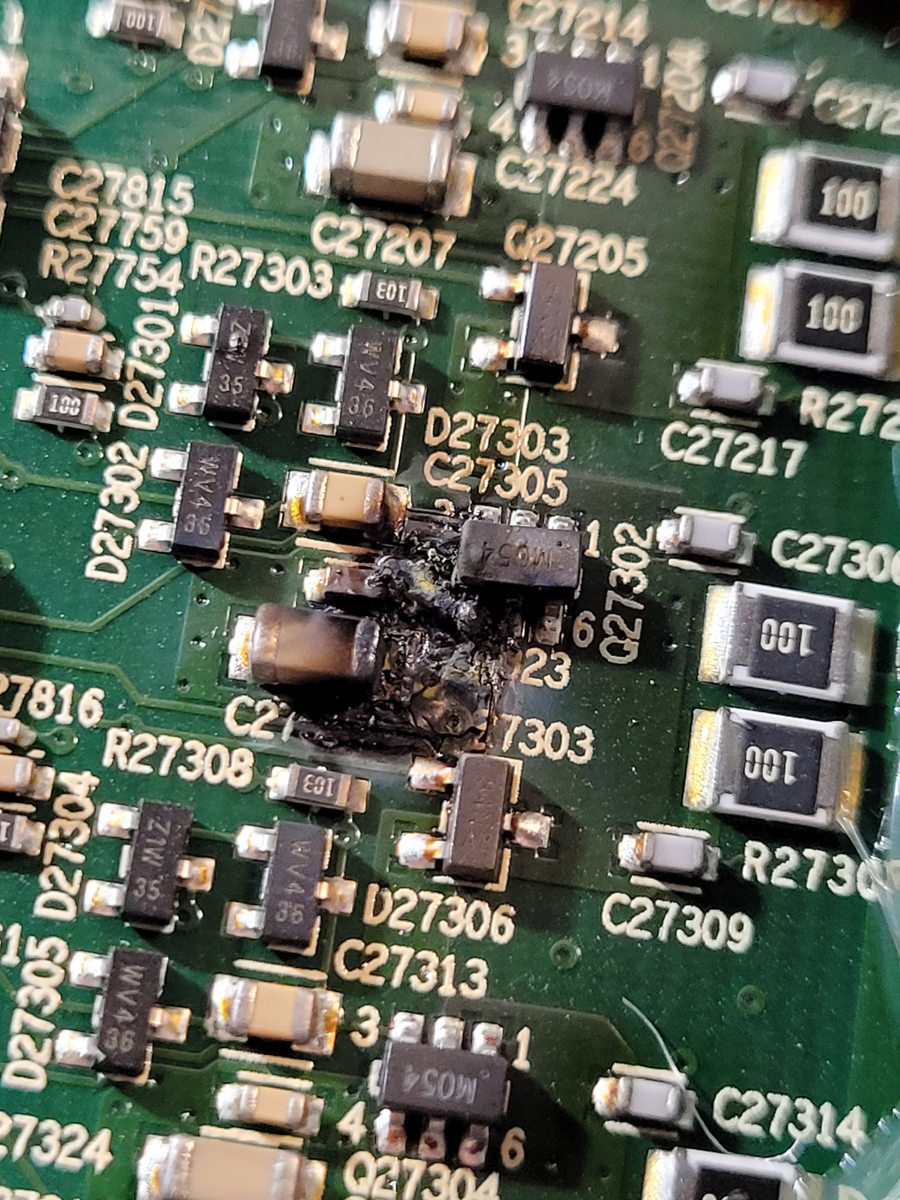
Now when I visually check board at the amplifier section there is carnage with what looks like multiple failed components. See pics:
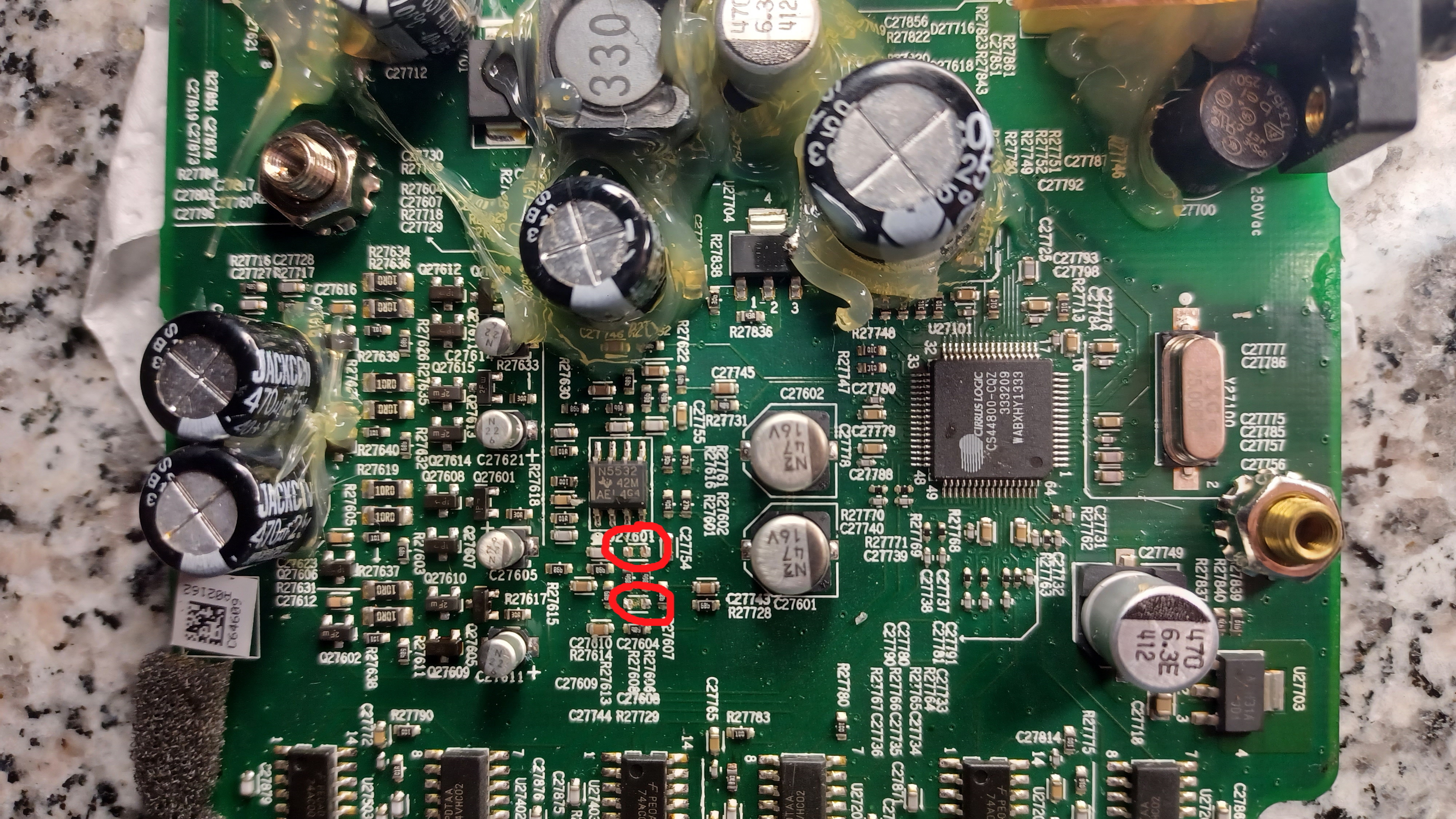
The capacitors C27604 & C27608 were barely attached by one leg and fell off as soon as I touched them, They look OK (tiny) one measures 3.5nF, the other 0.24nF...don’t know if this means good or bad? The fact that they were hanging off must mean they have blown?
Resistor R27852...looks bad and measures 2.7Mohms
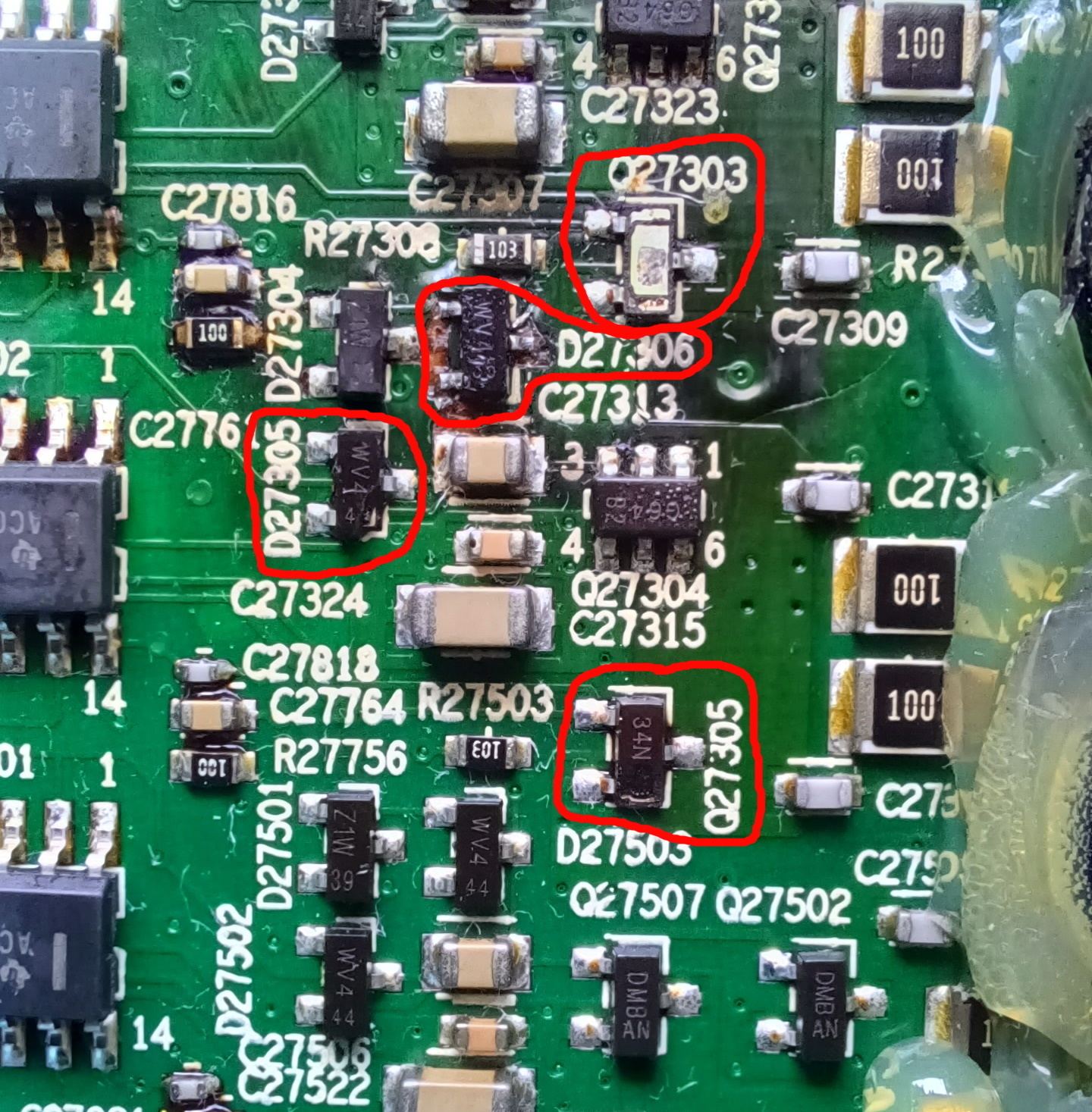
This is the biggy…..Q27303 has exploded, Q27305 and diode D27305 have split casing which I assume means they must have failed? Diode D27306 looks OK but board around it looks a bit cooked?
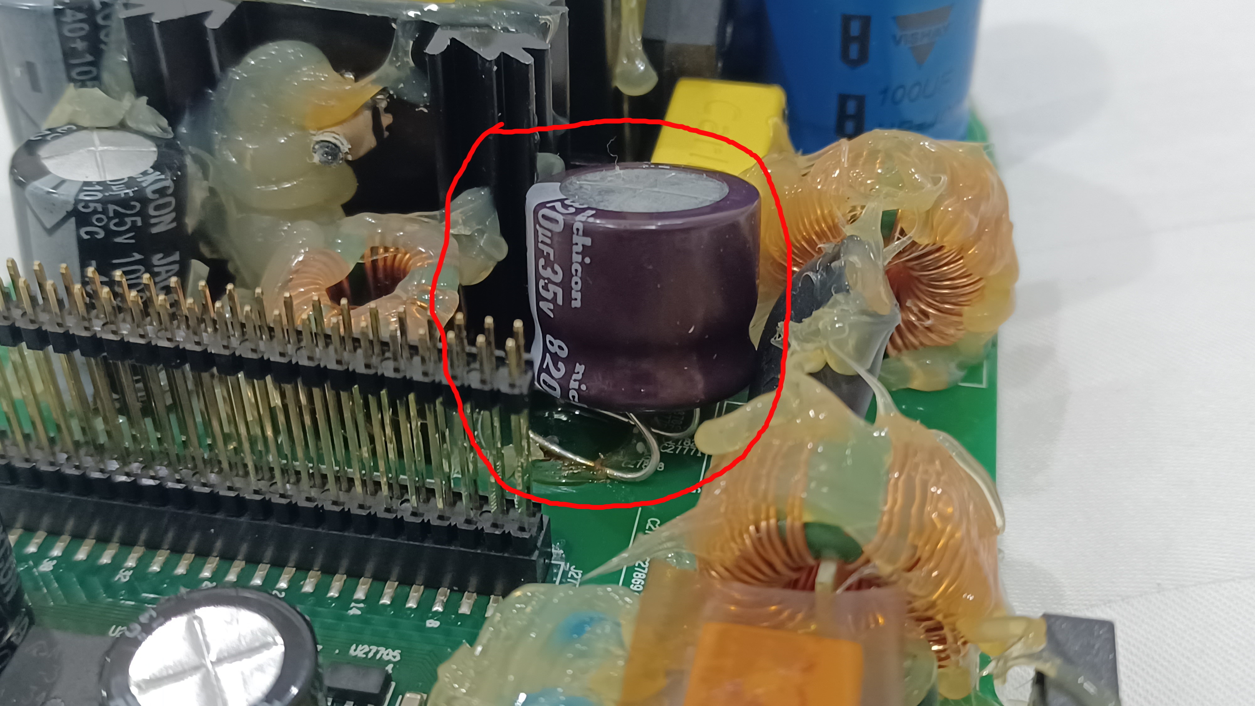
Lastly and this I’m assuming is nothing but this capacitor on the power section of the board is not connected, legs are just bent over and glued to board. Any idea what this is about. Its capacitor C27881.
So question….is it even worth or rather possible attempting to repair? I have no experience of surface mount electronics like this but do have a soldering station so…..happy to give it a go and see it as an interesting project. Bigger issue I’m guessing is identifying component and their availability.
So what do you think guys any and all thoughts gratefully received!
Hi there,
My sonos play 5 power board had some overvoltage and some parts are blown.
I managed to bring it back to life bij mounting a new PCB fuse3.15A and 2 capacitors 47K275V-X2
2 other components are broken and i cant determine what type they where.
Its about TH27700 at the inlet AC current side, i asume this is a NTC or PTC.
Also MOV27700 is broken, this should be a varistor after the first filter coils.
Does anyone know the partnumbers of these 2 components? You would realy help me out.
Thnx a lot!
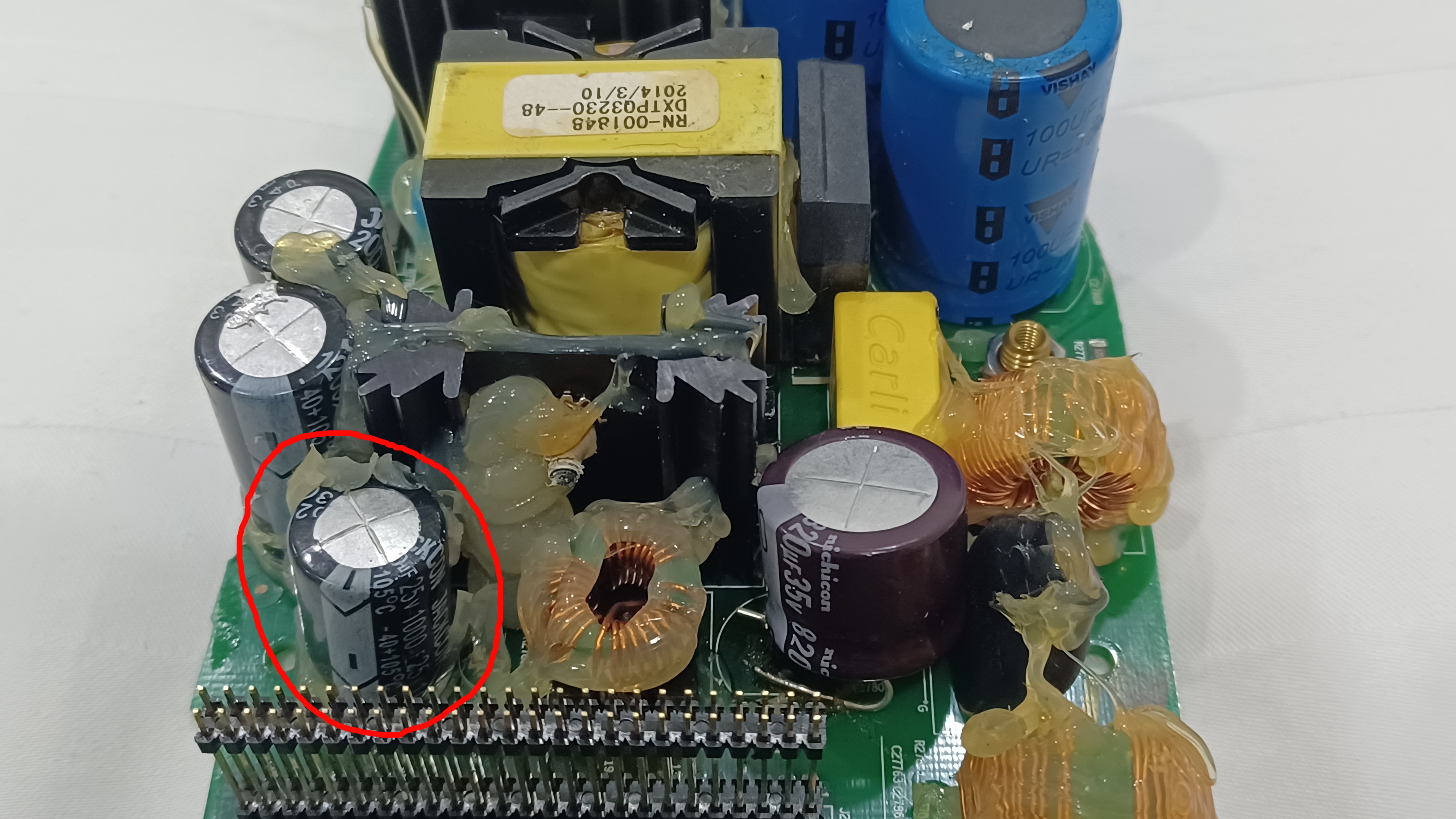
U definitely have capacitor issues. I would fix bad capacitors first and also mount that glued cap properly. The cap next to it have a bulge on top so its bad. Probably more caps.
Probably an Texas instruments SN74AC04 or 74AC04
U definitely have capacitor issues. I would fix bad capacitors first and also mount that glued cap properly. The cap next to it have a bulge on top so its bad. Probably more caps.
Thanks for that quick reply Ken. Now that you’ve pointed it out….yes capacitor next door does have a bulging top indeed well noted. I’ve looked in detail at all other big capacitors and that’s the only one with bulging top. That cap was one that has been previously removed and refitted. So that needs replacing but your also saying that the the one with the bent legs glue to board should be properly installed….wonder why anyone would leave it this way?
For clarity this is the cap with bulging top:
Yes thats the one thats bad. The other glued on...is it also soldered? Could be that track is broken on the other side of board so they mounted it like that.
Hi together.
I managed to repair a play 5 with power poroblems. Fuse, Rectifier and Caps were good, so i checked the whole thread here and found the problem. R27794 and R27796 were open.
Now i purchased another one. Poor speaker quality.
Sub and one middle speaker are working. So i opened it up and found it pretty easy.
unfortunately, i don´t find those parts. Maybe someone could help?
Q27202 and Q27204 are done. some caps too.
Thanks
Seems to be repairable but there is alot of work, skill and correct tools to get it right.
Yes thats the one thats bad. The other glued on...is it also soldered? Could be that track is broken on the other side of board so they mounted it like that.
Now that I look at it closely the furthest away leg is soldered on...just but the front leg is not, just glued! It looks...because this capacitor is maybe bigger diameter than the original, they thought it was quick and easy just to bend legs and fit in this way…..clearly very badly! So sorting out these easy to fix capacitors on the power side of the board will give me a bit of practice!
Seems to be repairable but there is alot of work, skill and correct tools to get it right.
mmm skill I don’t have...tools I can acquire. From somebody with no experience these tiny capacitors look the most difficult...is there any way I can find out what they actually are?

For me the voltage on that pin grows slowly, then falls to 5-10v or so, then starts climbing again and repeating the cycle. Even when I inject 13V to that spot from a bench supply it doesn’t help.
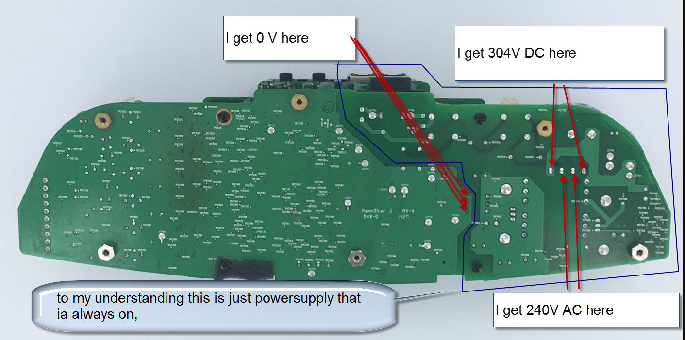
Typical SMPS supplies switches a high voltage via a MOSFET into the primary side of the transformer. That switching is controlled by the 2QS02G. I tried replacing it with no luck, and couldn’t find anything else off around it. What I did find though, was that the high voltage was 160V. I measured it as marked in the attached image. This is a problem for me, since when I measured a known good device, the voltage was 274V. The 160V seems to just be the rectified AC, and is not boosted to 274. I can’t figure out the mechanism that is causing the 274V to be produced, so am stumped. Any ideas?
Hello,
From what I understand now, your board does not start, when the voltage on 2QS02 goes up to 20 and the chip powers on, there must be an error that makes the chip to shut down immediately, thus not self-sustaining to 13V. The power on the caps is simple rectified by the bridge, try to measure on another type of switch power supply. Me I got-it from 110V AC so it goes around that 160V I believe ( I did not wrote down the value. Yours if it is 220VAC so it might be 274 or a bit higher rectified. Maybe your rectifier bridge is broken ( one diode is interrupted, so it’s half of the voltage. This driver chip checks for the voltage, locks for undervoltage. The rectifier is your problem. Check for that.
Regards
I don't think that’s right. My input is 113V, and the rectifier is producing 160V (as expected … ie: 113*1.414). If I had 220V, then I would expect to see 320V coming from the rectifier.
The 274V that I measured was from a working unit… not the one that doesn’t work. It could be that when the system is oscillating properly, my meter is getting a bad reading due to the high frequencies present and some kind of induced voltage into the supply. SMPS oscillators often oscillate well above 100kz, and perhaps my meter isn’t giving an accurate measurement at this kind of frequency. If my broken board isn’t oscillating, I’m just getting the 60hz rectified output, and hence the 160V.
I just checked for the undervoltage condition. According to the datasheet, there is a resistor divider network. That seems to be set with Rvins1=1.5M, and Rvin2=20k. With the internal Vref of 1.25V, the shutoff voltage would be 95V (1.25*(1520000/20000)). I never see my rectifier output drop below 160V so I don’t think that’s the problem.
I think that my next step may be to check for an overload condition. The output on the low voltage side of the transformer is fed through a dual inductor. I may try to remove that and see if that stabilizes the input.
Yes, you are right I was not right… Got carried away with the 220V possibility.. It must be then an overload condition somewhere since the under voltage part is fine. The excessive current detection is thru one of the vertical big resistors I believe. It sucks there is no schematic to do precise measurements, maybe it’s value changed… Hope you will find the cause of this and let us know the fix for the future.
Regards
Hello,
Maybe someone here can help me With my problem With my Play 5.
I have Some exploded smd capacitors/resistors/transistors on my board.
Might someone know the values of the following components:
C27852/C27855/D27714.
I found a helpful picture on this forum to know what the resistor values are.
Hoping someone can help me.
Thanks in advance.
CNS
My right middle Speaker is not working. What can i check? I dont find the fault
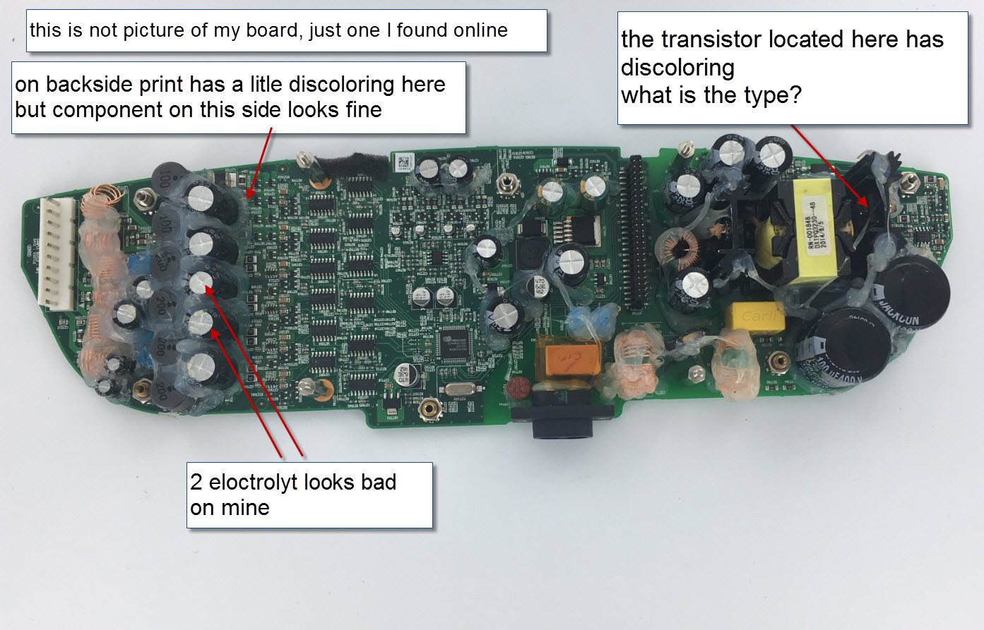
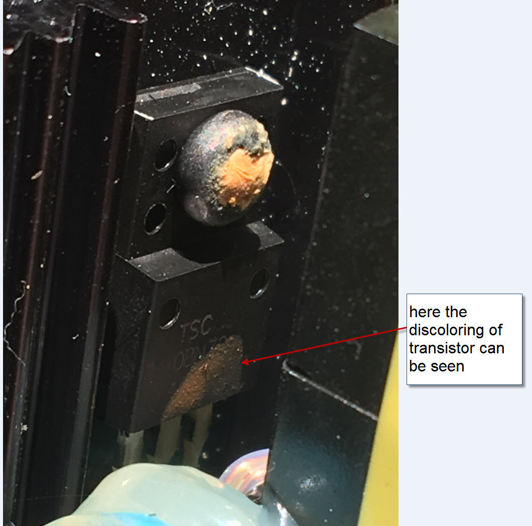
Hi I have not done more work yet
I am not sure that the transistor is the fault. The dis coloring could be rubbed off
I am not sure that the transistor is the fault. The dis coloring could be rubbed off
Hi guys!
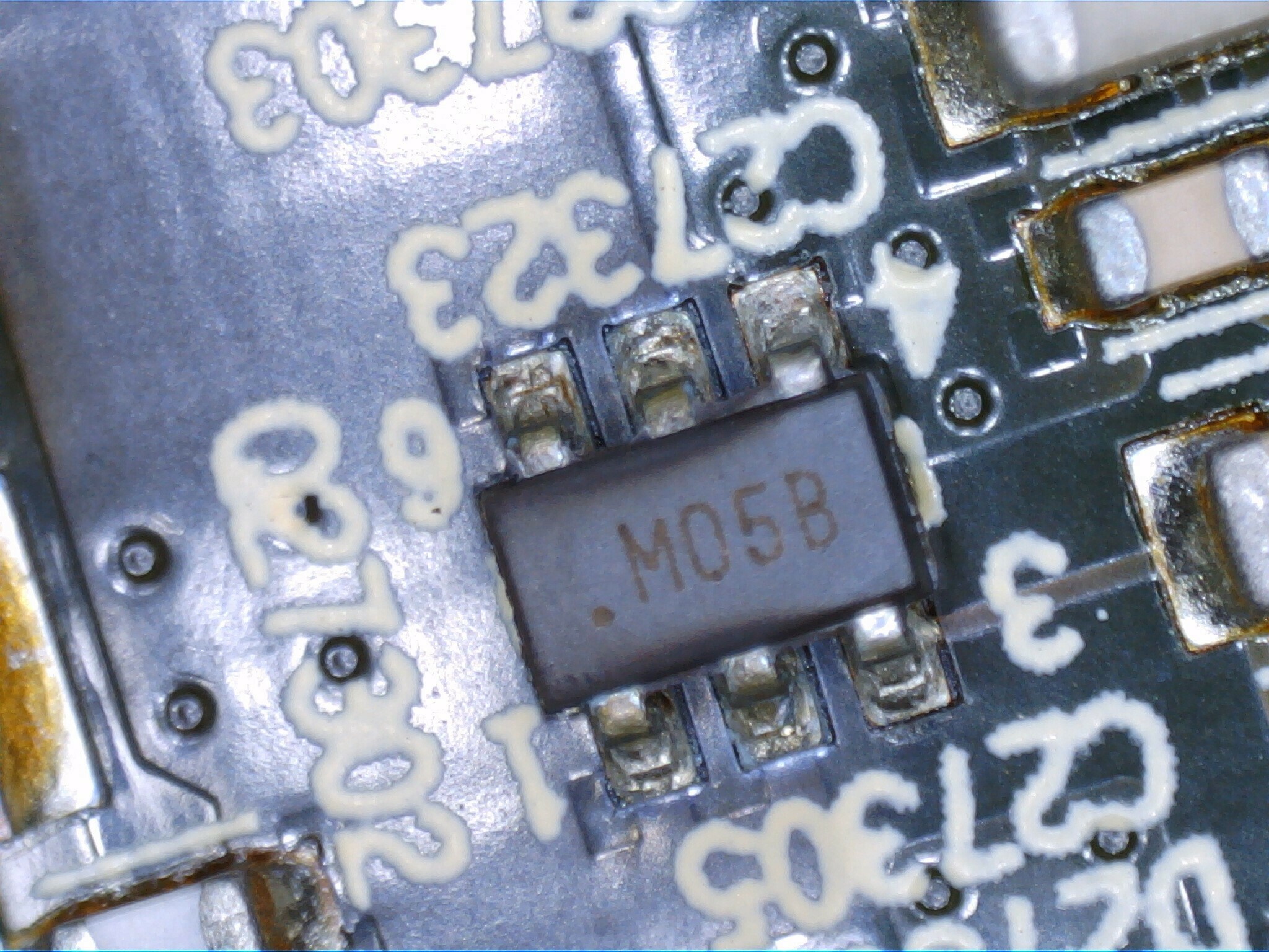
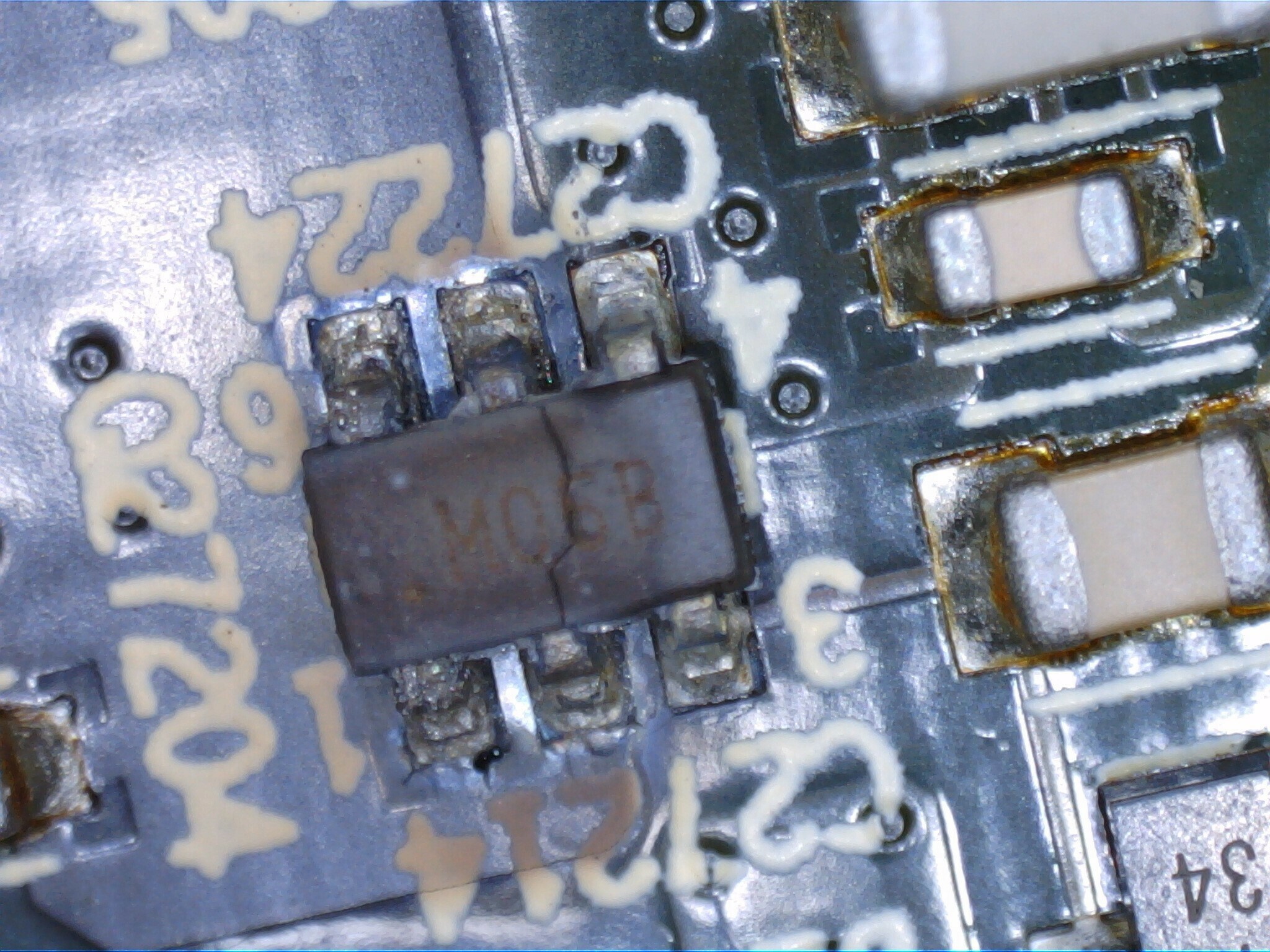
A component called “M054” seems burned at my Play 5 gen 1.
Do I need to replace more than this, I mean did it burn because of some other fault?
Anyone have an idea where to buy a “M054” from?
thanks!
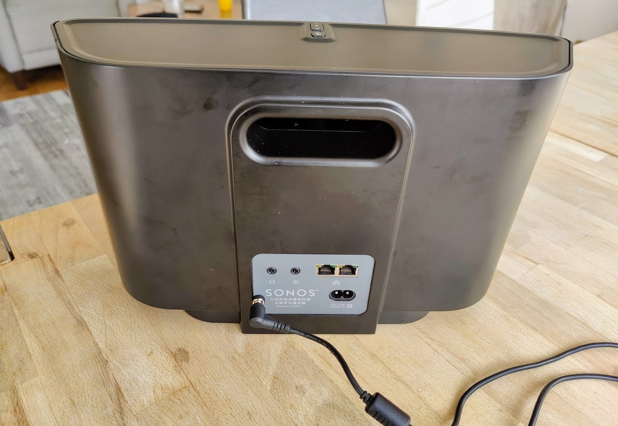
My Play:5 working again. If nothing helps you can power it with an external adapter.
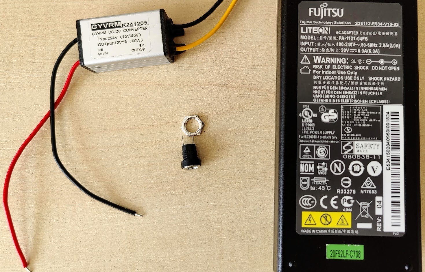
My setup:
- A laptop power adapter (20V - 6A)
- DC-DC converter (24-12V)
- DC connector (female)
The power is enough for max volume and there is no problem.
Thanks for the advice.
You beat me to it by a few hours! Nice job!
I just repaired mine too. I ordered a 24V/4A power supply very cheap on AMazon… $18CAD https://www.amazon.ca/gp/product/B08NYHM4J9/ref=ppx_yo_dt_b_asin_title_o00_s00?ie=UTF8&psc=1 . I chose this one because it was 250 grams, approximately 95 watts, and the size seemed like it would fit -inside- the case.
I had a few DC-DC converters on hand like this: https://www.amazon.ca/gp/product/B07Y88RTXJ/ref=ppx_yo_dt_b_search_asin_title?ie=UTF8&psc=1
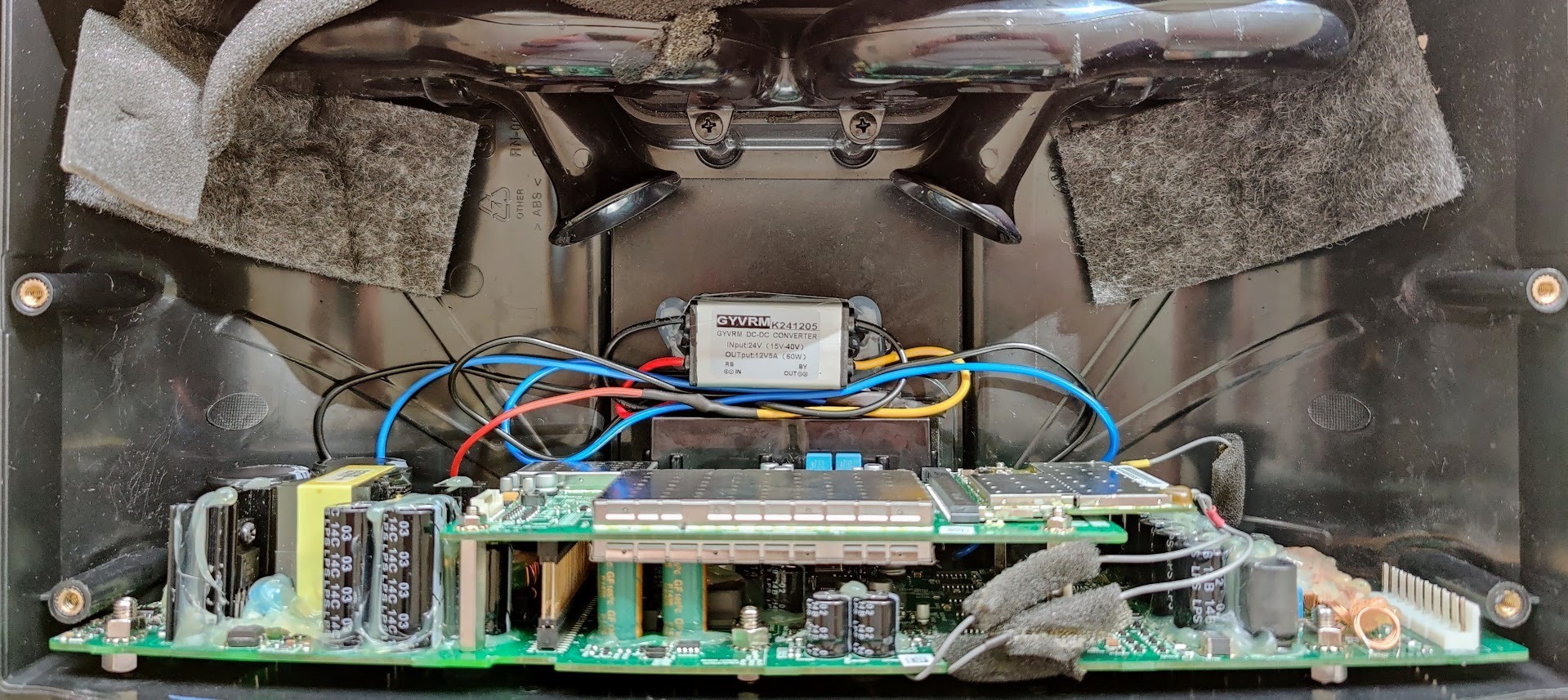
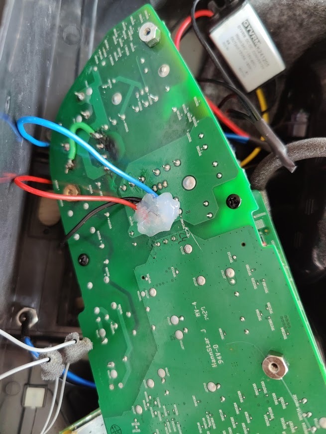
I was fortunately able to fit everything inside the case. I piggybacked the 120V supply to the AC-DC supply from the existing socket, and connected my DC-DC converter at the triple inductor like I had suggested a week or so ago. I opened the power supply case, removed the existing wires, and soldered it all in directly. I had to trim the two bass reflex ports about an inch, and was able to position the brick just below those centered between the two mid speakers at the back of the case. I wrapped the PS brick it in a sheet of foam to avoid vibration. It’s a snug fit, but everything went together perfectly. There is no vibration, and I can’t tell the sound difference between this and an unmodified speaker.
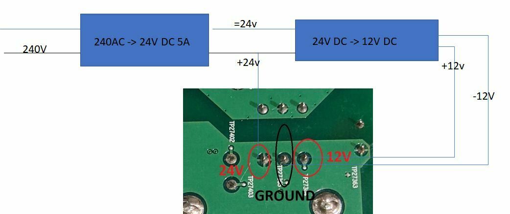
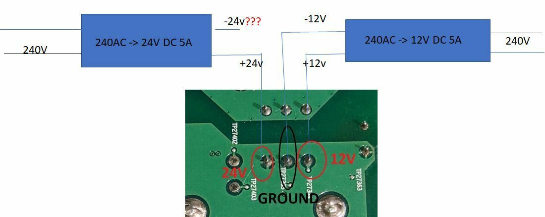
Can anyone help clarify if the below diagrams look correct, completely unsure where the -12 V and -24V lines go to,? both to ground?
hi my 7 years old play 5 has also now stopped working. opened it up hoping it was the fault decribed with fuse and rectifier, but they are both fine,
have anyone fixed this error.
have anyone fixed this error.

Page 5 / 9
Enter your username or e-mail address. We'll send you an e-mail with instructions to reset your password.