Hi
Play:5, manufacturing date sometime around 2009, is completely dead. No light in LED.
Found several cases of this online, but no solutions.
Does anyone have any knowledge about the problem, og better yet, schematics..
I mainly suspect problem in switch mode power supply. Have only done very basic measuring, but I find 220VAC on primary side, no power on secondary side. I think about ordering a mosfet, and/or a diode I suspect, but if I had schematics I could do some more pinpointing..

This topic has been closed for further comments. You can use the search bar to find a similar topic, or create a new one by clicking Create Topic at the top of the page.
Page 8 / 9
Which ones broke on yours? Nevertheless none of them seem to be damaged..
Mine did work right after i replaced the broken fuse&rectifier, the first time it broke. It then stopped working AGAIN 6 months later - but this time there was nothing wrong with the rectifier or fuse, so i don't think the problem has anything to do with the rectifier breaking...
Mine did work right after i replaced the broken fuse&rectifier, the first time it broke. It then stopped working AGAIN 6 months later - but this time there was nothing wrong with the rectifier or fuse, so i don't think the problem has anything to do with the rectifier breaking...

Here is the best I’ve found on debugging Sonos Play:5 hardware issues:
https://sites.google.com/site/sonosdebug/power-topology
The author includes reverse-engineered information about jtag, serial port, connector, and the power supply (including a very helpful partial circuit diagram)!
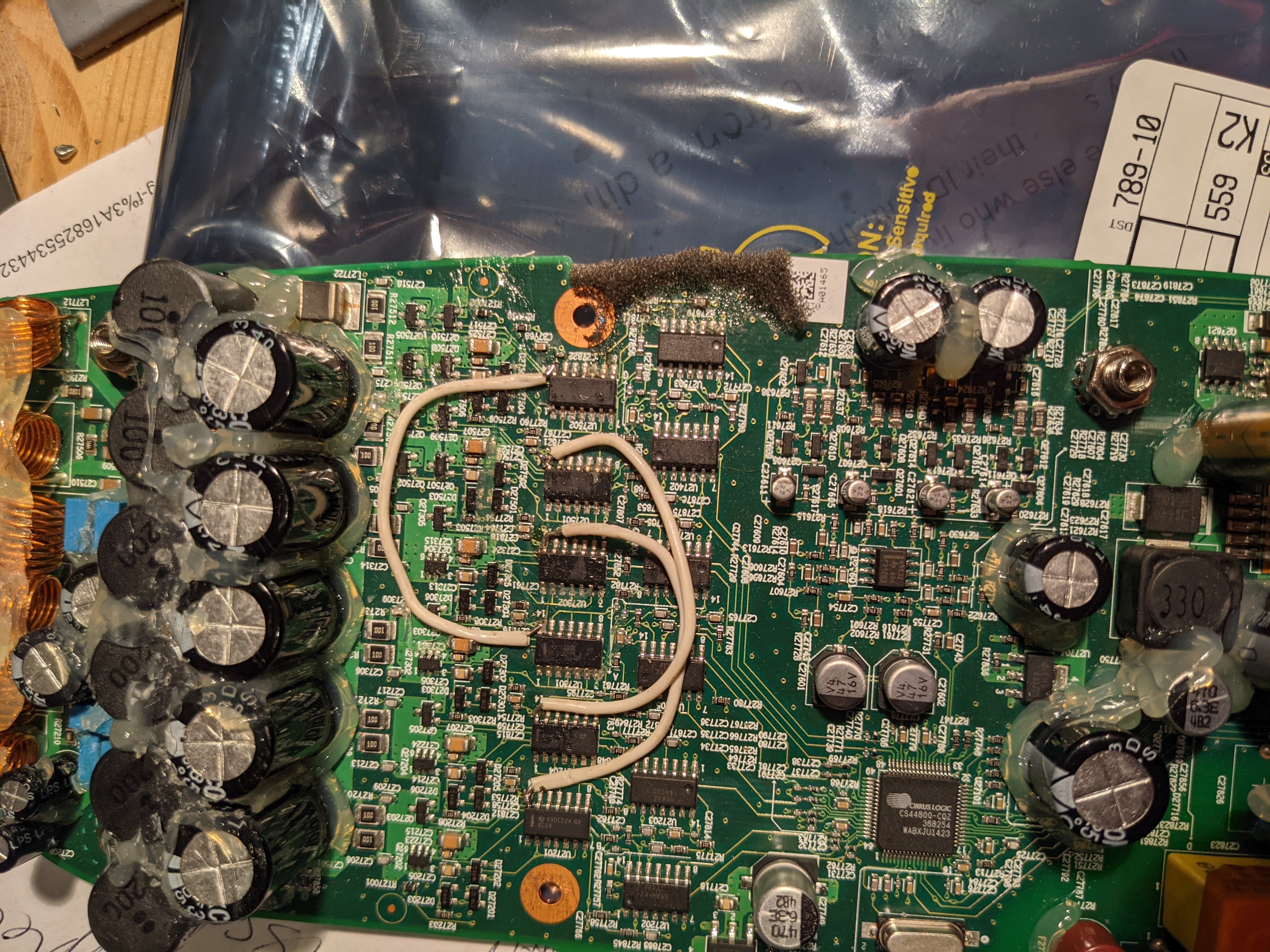
There is nothing about the actual power amp. I have seen a few of these go bad and had only marginal success fixing them. One finding I did have was that a unit with missing bass had some of the driver ICs not having power. It turned out that some of the internal traces had burned out between the driver chips. I jumpered all of the power pins of the 6 ICs together (and all of the grounds too, for good measure), and it solved the problem.
If you have NO sound from the amplifier, then check the biases identified on the schematic and make sure that all of them (12v, 3.3V, 11.1V, 5V) are working.
Hi Tim,
Is your play 5 having issue of very soft volume? Then you jumpered the traces and that fixed it?
Hi. Sorry for the late response. I was locked out… Can't log in
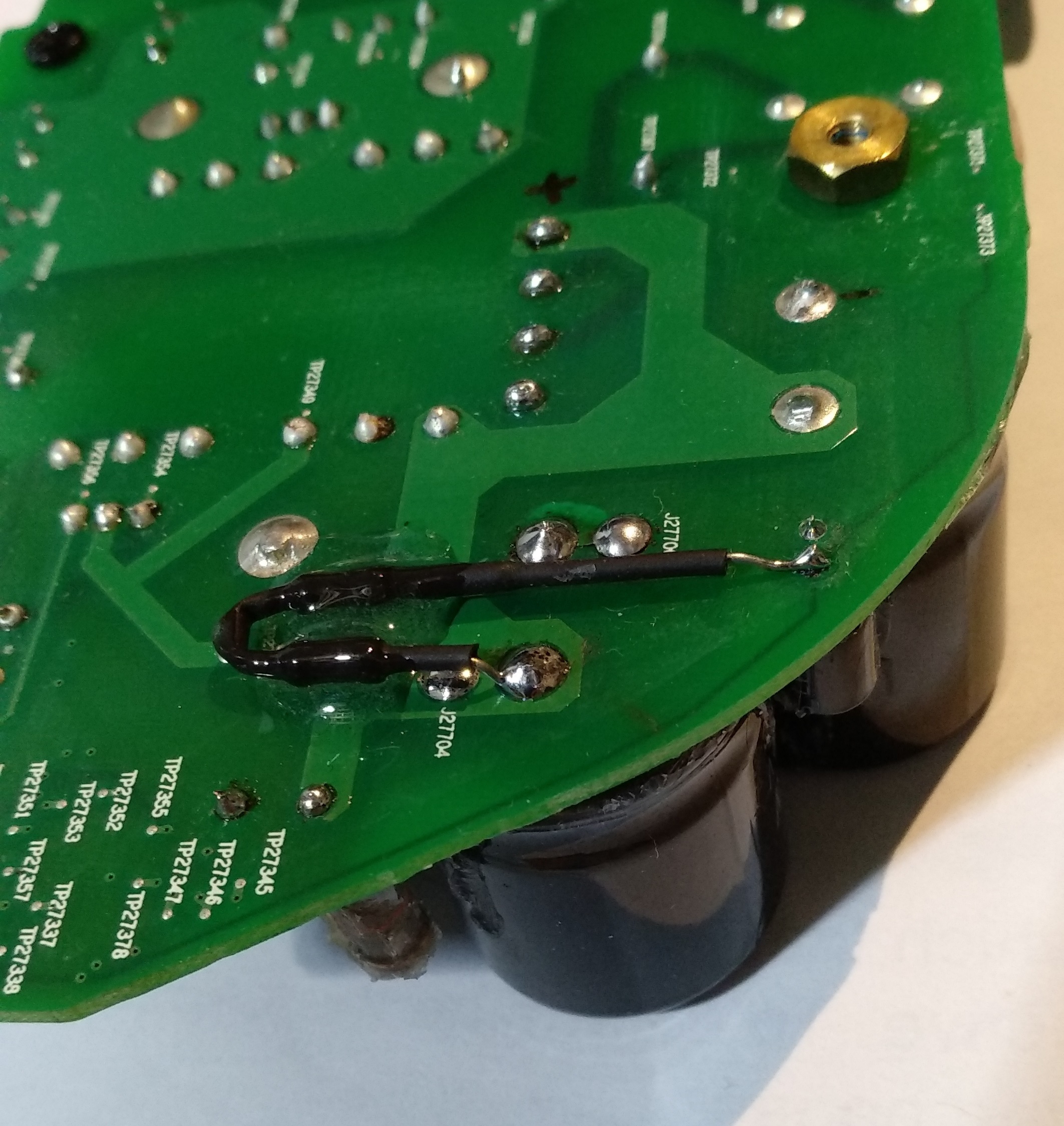
The problem that I had was that of the 5 speakers, some were working and others were not. I found that some of the driver chips did not have power and was able to add power to them… after which it all worked again. Here is a picture of what I jumpered. I think that this was not the complete job… but you should get the idea from here.
Thanks Tim. Unfortunately my play 5 issue is not the same issue. All the pins have 5V to it. Headphone out is working fine, just the all speakers have a very faint sound.

For me the voltage on that pin grows slowly, then falls to 5-10v or so, then starts climbing again and repeating the cycle. Even when I inject 13V to that spot from a bench supply it doesn’t help.
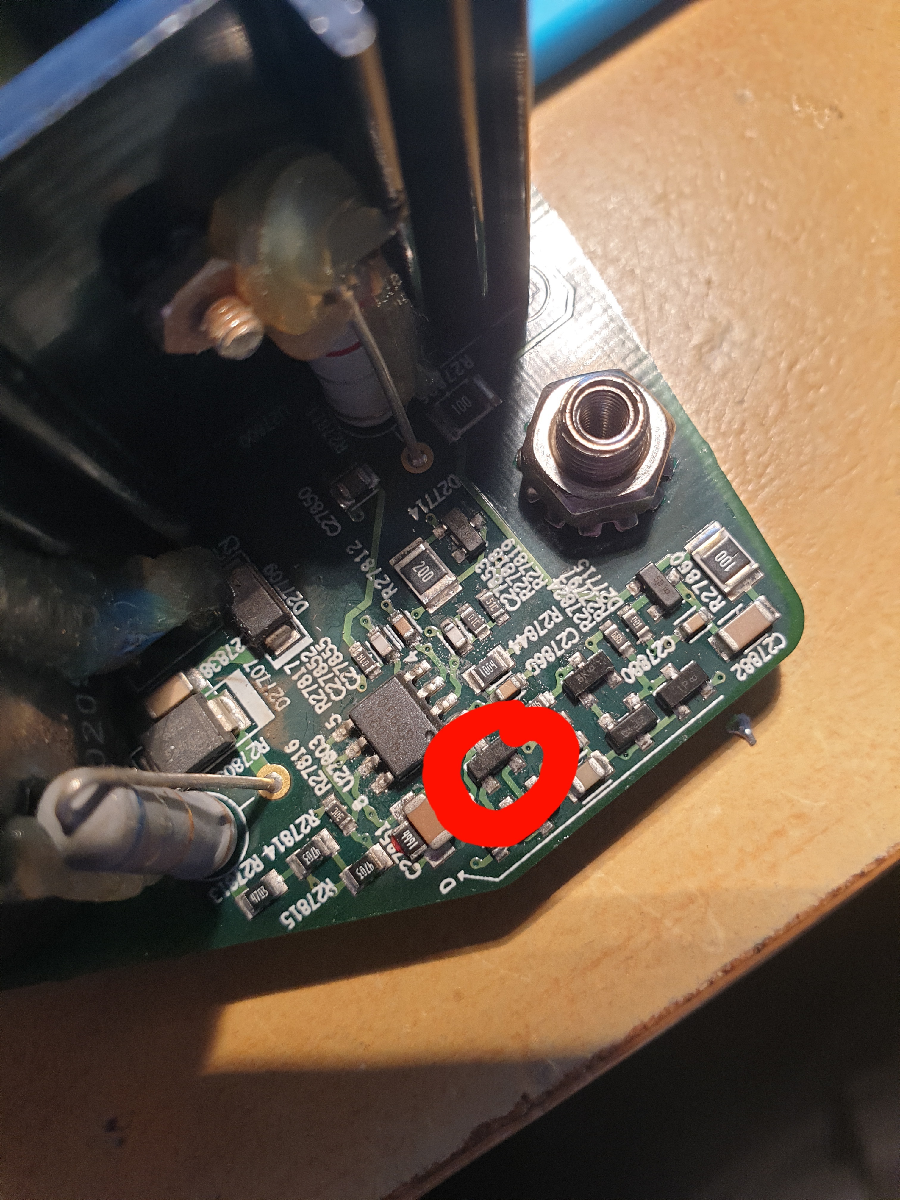
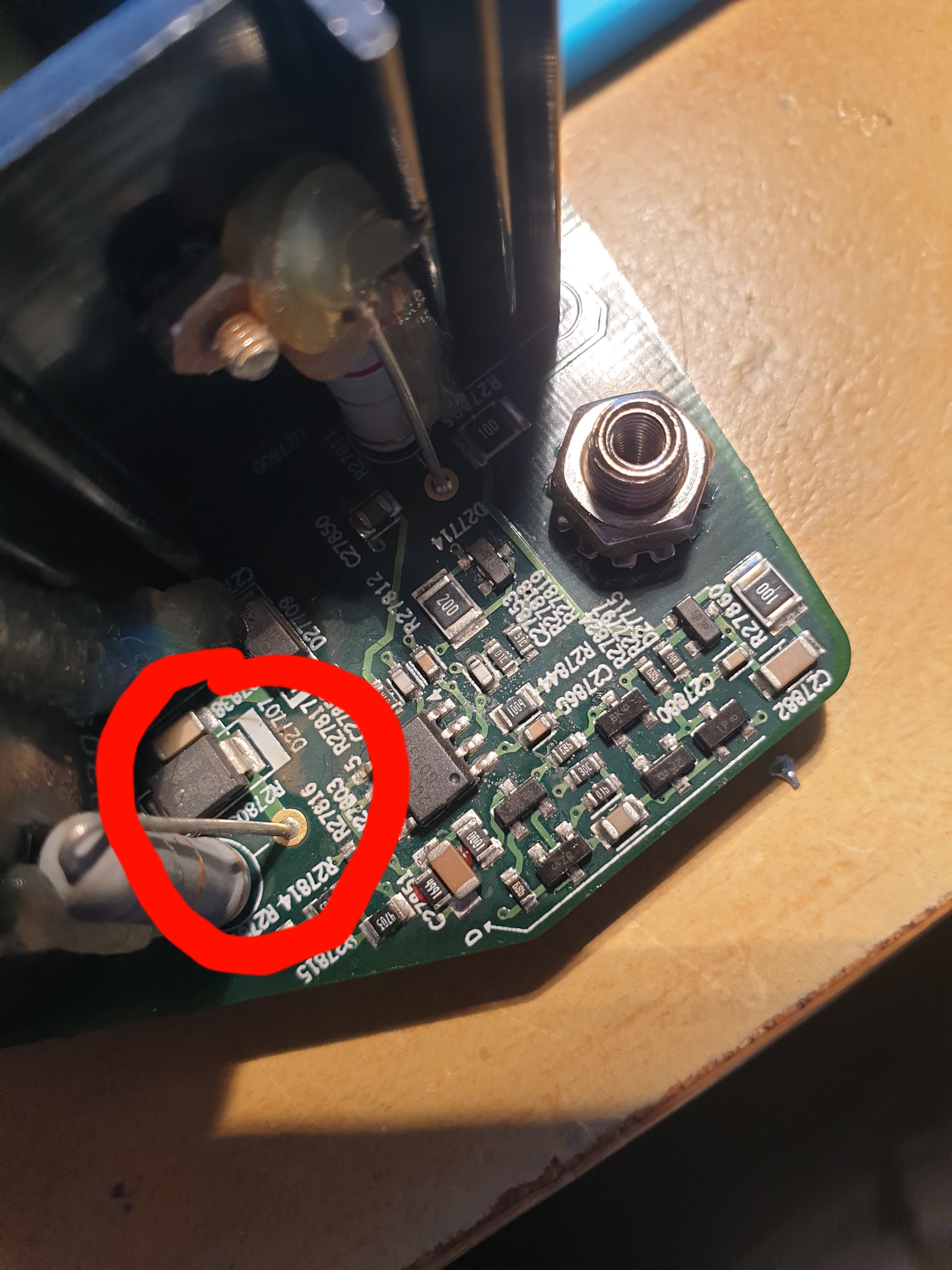
Typical SMPS supplies switches a high voltage via a MOSFET into the primary side of the transformer. That switching is controlled by the 2QS02G. I tried replacing it with no luck, and couldn’t find anything else off around it. What I did find though, was that the high voltage was 160V. I measured it as marked in the attached image. This is a problem for me, since when I measured a known good device, the voltage was 274V. The 160V seems to just be the rectified AC, and is not boosted to 274. I can’t figure out the mechanism that is causing the 274V to be produced, so am stumped. Any ideas?
Hello,
From what I understand now, your board does not start, when the voltage on 2QS02 goes up to 20 and the chip powers on, there must be an error that makes the chip to shut down immediately, thus not self-sustaining to 13V. The power on the caps is simple rectified by the bridge, try to measure on another type of switch power supply. Me I got-it from 110V AC so it goes around that 160V I believe ( I did not wrote down the value. Yours if it is 220VAC so it might be 274 or a bit higher rectified. Maybe your rectifier bridge is broken ( one diode is interrupted, so it’s half of the voltage. This driver chip checks for the voltage, locks for undervoltage. The rectifier is your problem. Check for that.
Regards
I don't think that’s right. My input is 113V, and the rectifier is producing 160V (as expected … ie: 113*1.414). If I had 220V, then I would expect to see 320V coming from the rectifier.
The 274V that I measured was from a working unit… not the one that doesn’t work. It could be that when the system is oscillating properly, my meter is getting a bad reading due to the high frequencies present and some kind of induced voltage into the supply. SMPS oscillators often oscillate well above 100kz, and perhaps my meter isn’t giving an accurate measurement at this kind of frequency. If my broken board isn’t oscillating, I’m just getting the 60hz rectified output, and hence the 160V.
I just checked for the undervoltage condition. According to the datasheet, there is a resistor divider network. That seems to be set with Rvins1=1.5M, and Rvin2=20k. With the internal Vref of 1.25V, the shutoff voltage would be 95V (1.25*(1520000/20000)). I never see my rectifier output drop below 160V so I don’t think that’s the problem.
I think that my next step may be to check for an overload condition. The output on the low voltage side of the transformer is fed through a dual inductor. I may try to remove that and see if that stabilizes the input.
 +1
+1
I have no idea, but can tell me somebody, what part it is,it is brocken. There is writtrn "2F8".
Hi all,
I would love some help debugging my unfortunately broken play 5 gen 1. I got off the phone with sonos and the best they can do is repair it for the same cost as basically buying a brand new one. I really don’t want this to go to landfill but I’ve exhausted my expertise on this device.
symptoms:
AC side of the device: OK - I get roughly 320V DC from the bridge rectifier.
I get a range of voltages supplied to the PWM chip from 9-20V. Oscillating at roughly a 4 second frequency.
the output side of the transformer is sitting at 2V roughly. I think this means that the mosfet is okay which switches the transformer. Pointing me back at the PWM chip.
Current attempts at solving the problem:
I’ve poked and prodded at all the small resistors but wasn’t able to find any broken ones next to the PWM chip or on the feedback loop to it. I can’t work out what type these transistors are so I can’t test them.
ive replaced the PWM chip and get the exact same functionality as before.
Does anyone have any advice on how to verify these transistors? Or anyone fixed a device with similar problems and have some debugging advice on how to break the problem down into smaller search area.
Thanks!
Yay it lives... wired only. It worked out 2 of the traces imside the pcb was damaged tbat bles the fuse cap and rectifier.
So nee problem. Basically the guys who bukld these poxg the sma to the board.. they are no bustdd so im relyinv on some solid core cable as replacement to the positive pin which is still present on all 3
Yer rhere is thats the next component. But i have pulled this box out and im unabke to vet any reading from it. So im changing this then keep working backwards.
What voltage should i get on botg of those ac pins... across the pair 240 v ac or 2r0v ac on both ?
So the plot thickens. I repla ed the box cap with a new one that tests ok.. the old is ol. Howerver i still only get around 100 v dc on the rectifier.
Confused .com
You should have the full mains voltage, 240V AC on the rectifiers AC pins.
Start at the input jack and measure and see where the voltage disappear.
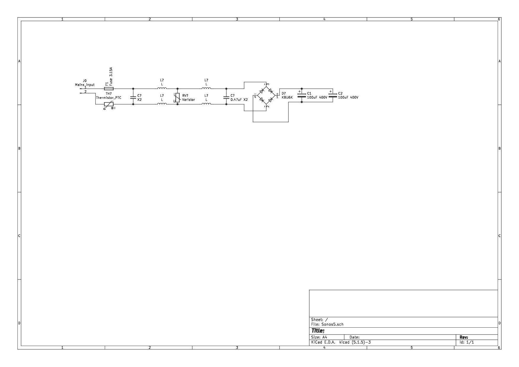
I did a quick and dirty schematic over the incoming power section,
I don´t have a Play5 with me so I can have missed something
Hi, The KBU606 is available on Digi-Key and other distributors.

Hello, first of all sorry for my bad English. I have the following problem, my play 5 gen1 only outputs sound over sub and high. Midrange is dead. I'm already disassembling the play5. You can't see faults with the eye. Which components are responsible for the center? I would be very grateful for tips.
I would start checking the power amp (where there is a row of 5 capacitors). Top of the cpacitors should be flat. Are you sure yours are not bulged? I had 7 bad caps, the row of 5 and 2 smaller ones next to it.
Yay it lives... wired only. It worked out 2 of the traces imside the pcb was damaged tbat bles the fuse cap and rectifier.
So nee problem. Basically the guys who bukld these poxg the sma to the board.. they are no bustdd so im relyinv on some solid core cable as replacement to the positive pin which is still present on all 3
That´s good that you find where the problem was.
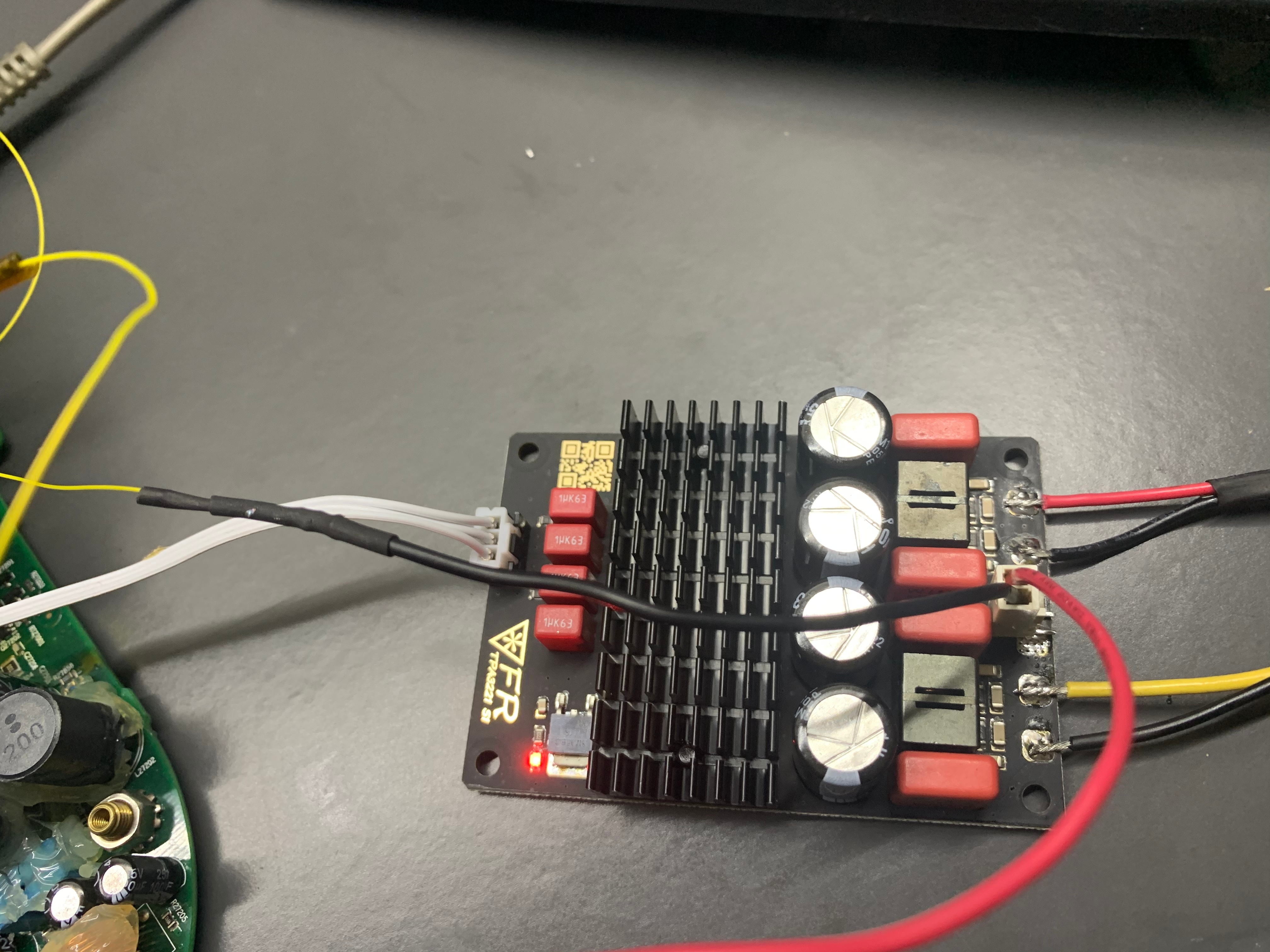
Last resort is to add in a class D amp to it. Not ideal at all, but at least, sound is back.
There are a fair number of play:5 units for sale on ebay from time to time - many of which are in recycle mode. If you pick one of those up, the power/audio board is often in good working condition, and you can swap that into your unit. There’s a bit of risk to this, as the play:5 may have had an audio problem before it was bricked, but perhaps the seller can tell you the history, or you can take a bet on the purchase.
Thank you for your reply. I removed the 7 caps today and am waiting for the new ones. I hope it will work again.
Hello, thanks for the picture.
I have-it fixed finally but I do not know the cause. Here it is in words and pictures:
First, small cap (C27854) is not charging from the AC side, those are probably discharge resistors to the remaining capacity in the filtering caps. It’s another mechanism I could not figure out. The C27854 is providing power to the ICE2QS02 driver chip. It goes thru all those small diodes and caps on the edge of the board. The normal behavior on the voltage for C27854 is that is charging up to around 20V slowly and then ( some of those diodes and transistors do that) turns on the power on the ICE2QS02.
Once the chip is starting the voltage is self sustaining to around 13 V, I do not understand from where, maybe from the fly back transformer winding itself.
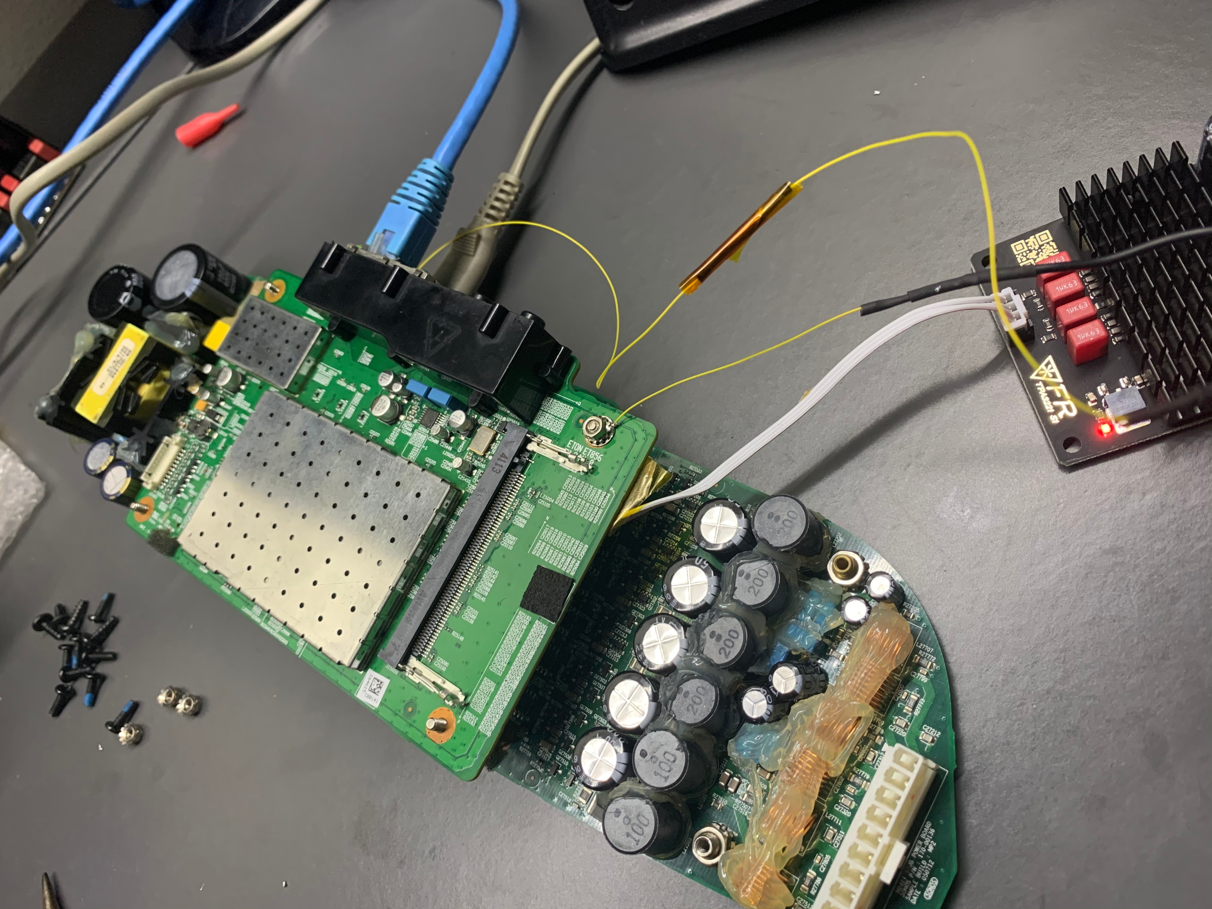
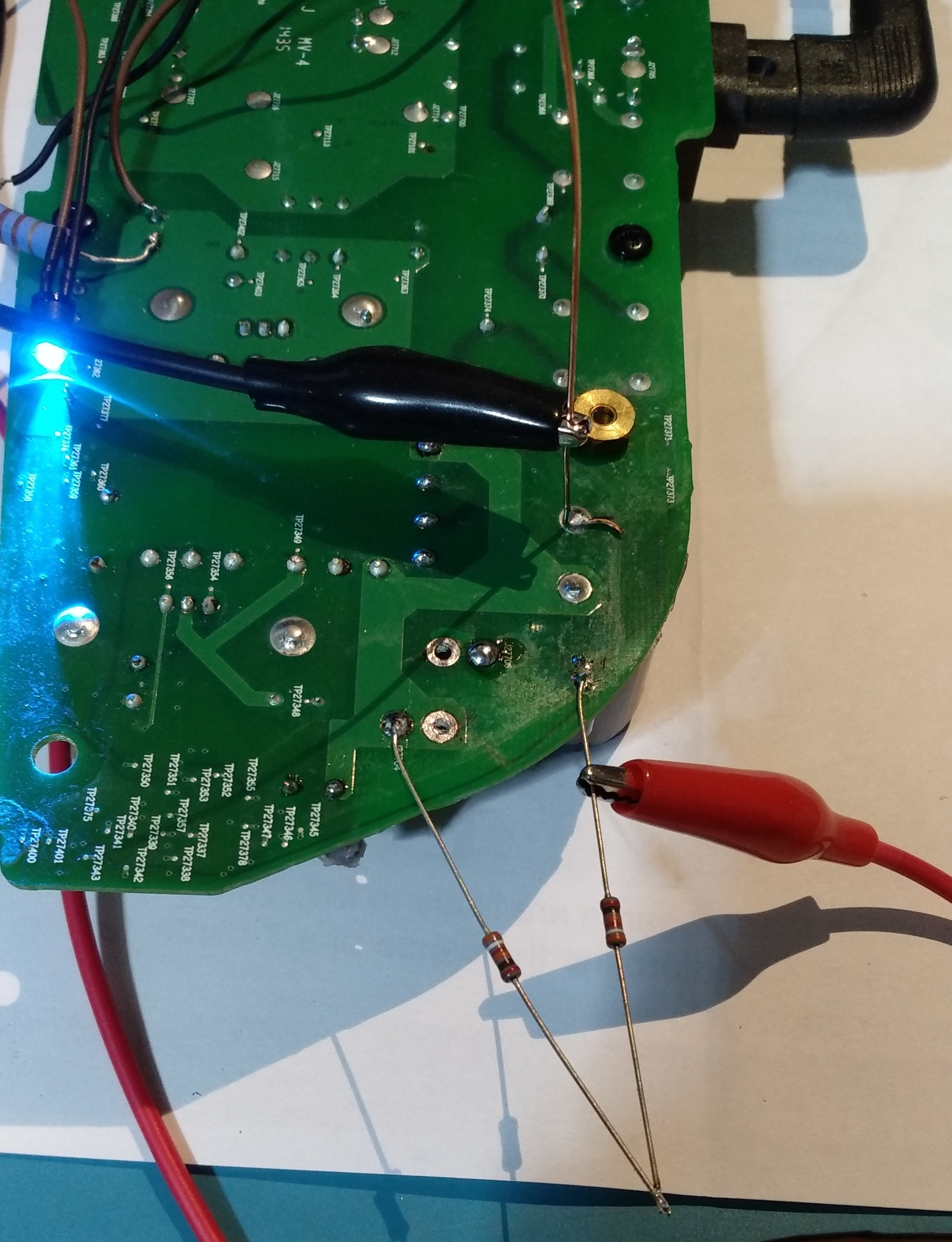
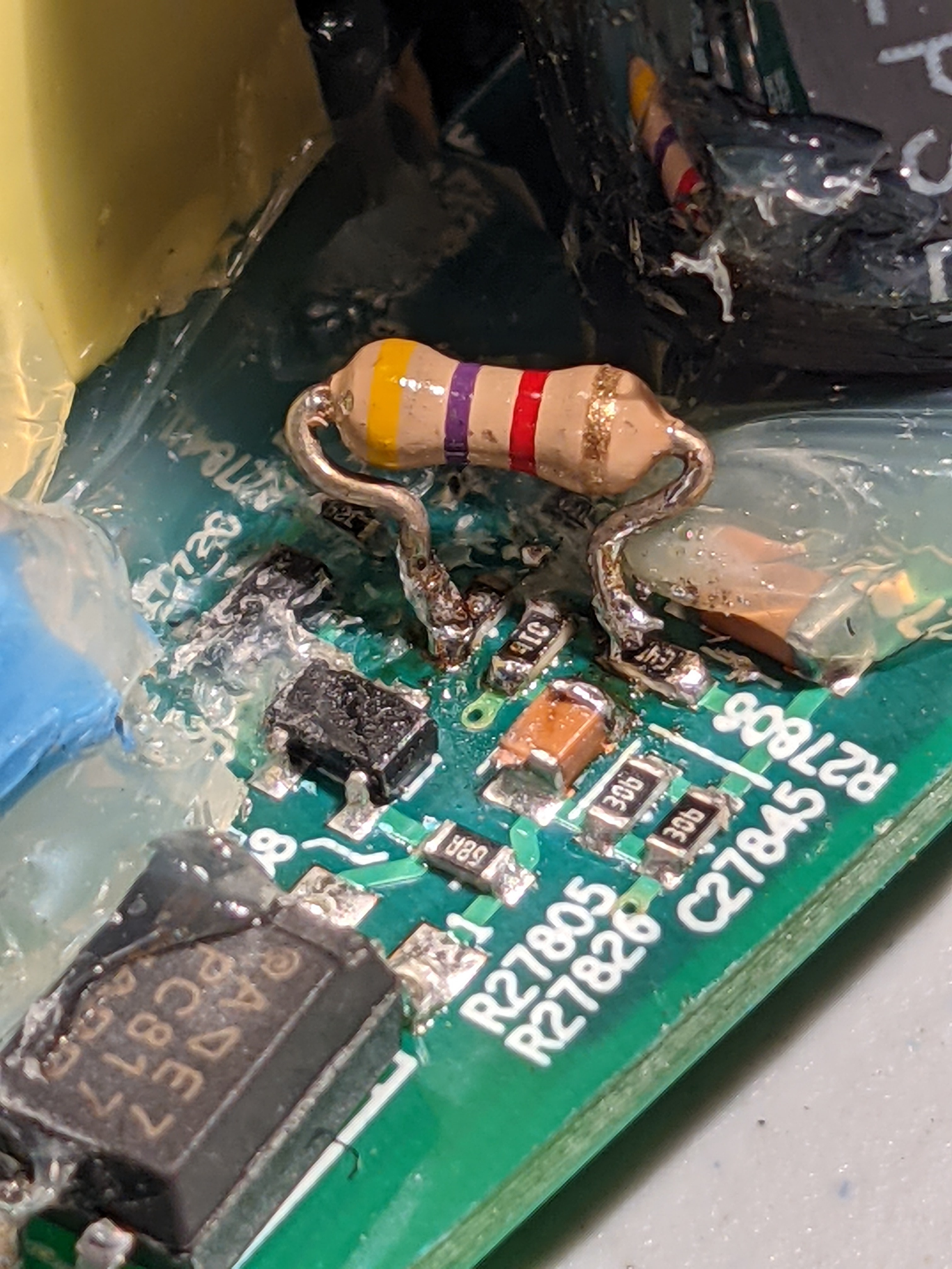
So for me the challenge was to produce the charging of the C27854 up to 20 to start up the IC. I did this by putting 2 390Kohm from the + on the big caps. I monitor the voltage and it’s ramping up slow, like a second or two. After it reaches 20V the IC starts and it self sustain to 13V. It’s 3 days already and still works! meaning there is no other fail. There was no problem in the fuse or rectifier, nothing burned. As you can see the LED turns on with the 2 resistors soldered. This is the story of this fix.
I have no power on pin 7 on ICE2QS02 and when i measure on C27854 it goes from 9 to 18 VDC in a 2-3 second loop, is this the same behaviour as you had?
a normal board ,the C27854 is 15VDC, the pin 7 on ice2qs02 is 1.5 VDC
I have two broken Play:5 units and when i check the “68b” resistor on them one reads 4.5 kOhm and the other one reads 12 kOhm, could the one that reads 12 kOhm create the problem you describe
My god. Fat thumbs and small keyboard.. my typing skills need looking at.
Yer so one of the traces to an ac leg on the rectifier was broken also the negative on the dc side of the rectifier to the first cap trace was blown. I wired them direct I also had to replace the fuse rectifier and the box cap.
I have to hard wire it because when i aped the sma cables off the board i busted the connectors because of the glue everywhere. However the centre pin on all 3 board connections are present.. ill have to re solder some wires to them from tbe antennas. Hopefully itll work on wifi/bluetooth then. Thabks all.
That diagram is pretty precise by the way.
SO… My success 2 days ago inspired me to have another look at the two other dead units that I have.
I found a common problem to both of them, and got both working!
I had looked at everything in the high voltage section of the power supply, and couldn’t find any bad components. Despite this, the devices were both not working, and on closer inspection were resetting about once every 5 seconds… There was power ramping up, and just as it hit 20V in the driver power to the IC, it would fall back to 10V or so and start over. This is a problem that others have had on this forum (and in this thread).
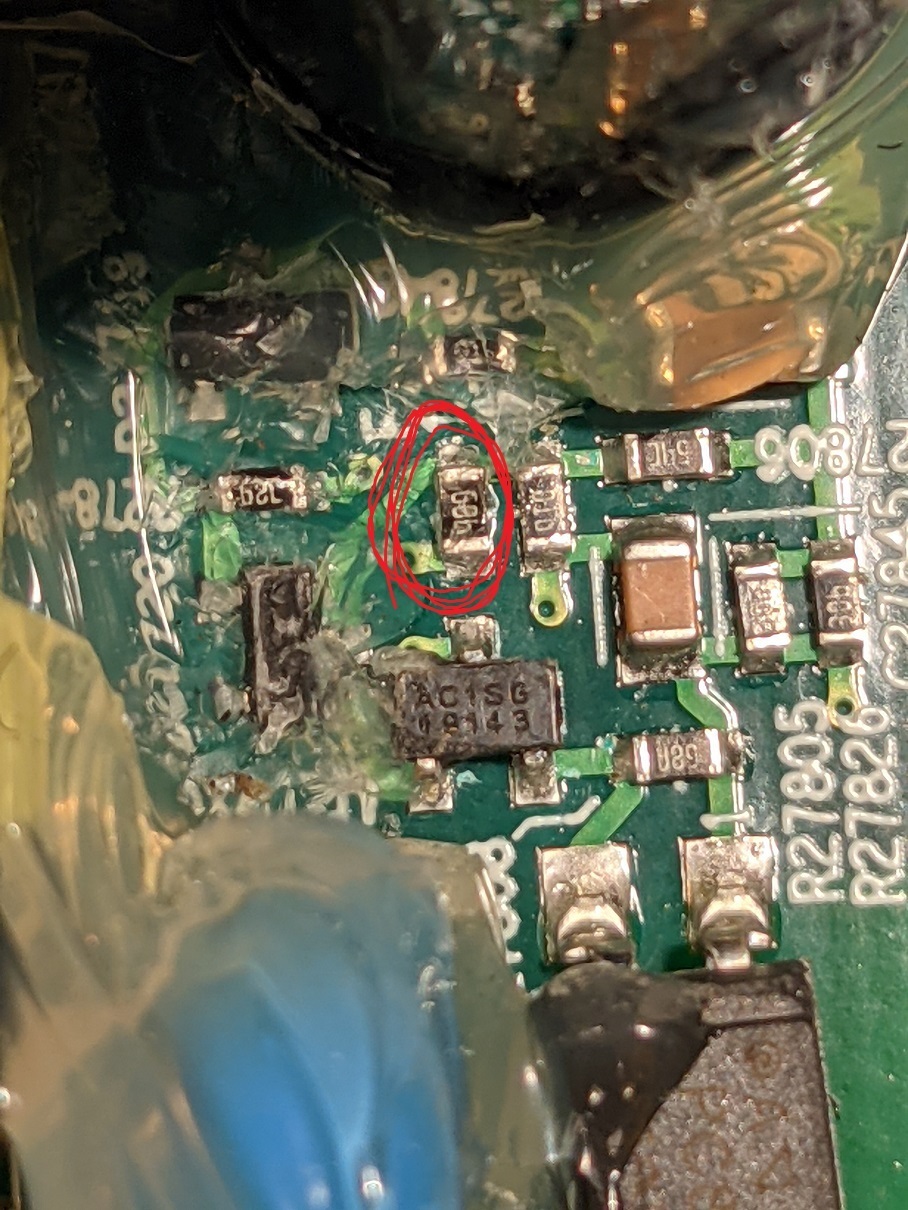
I looked at the datasheet for the PWM (ICE2QS02G), and realized that I had not checked the feedback section of the circuit. This is the bit on the ‘other side’ of the opto-isolator. Most of this part of the circuit is buried in glue, but sure enough, when I checked the resistors there, both of my devices had bad resistors in the same spot! The resistor in question is a very small surface mount, with the marking “68b”. Looking in the EIA listings , this is a 4.99k resistor. Both of my devices had open resistors. I added 1/8 watt 4.7k resistors (I didn’t have 5k), and lo and behold both devices now work.
The lower value resistor did have the effect of making the device run at 13V/26V instead of 12V/24V. I don’t see this as a problem, as there are several EH31 regulators on the board, and the only thing (I think) that would be driven directly by these voltages would be the actual audio amplifiers. Those should be tolerant.
Thank you for your persistence. I had the exact same fault! I don’t think I would have suspected an open resistor in the feedback circuit, such a strange defect. Replaced the resistor together with two ultra cheap bulging „CapXon“ 470uf/35V caps on the secondary side next to the DC/DC converter. Working again like nothing ever happened. Thanks again!
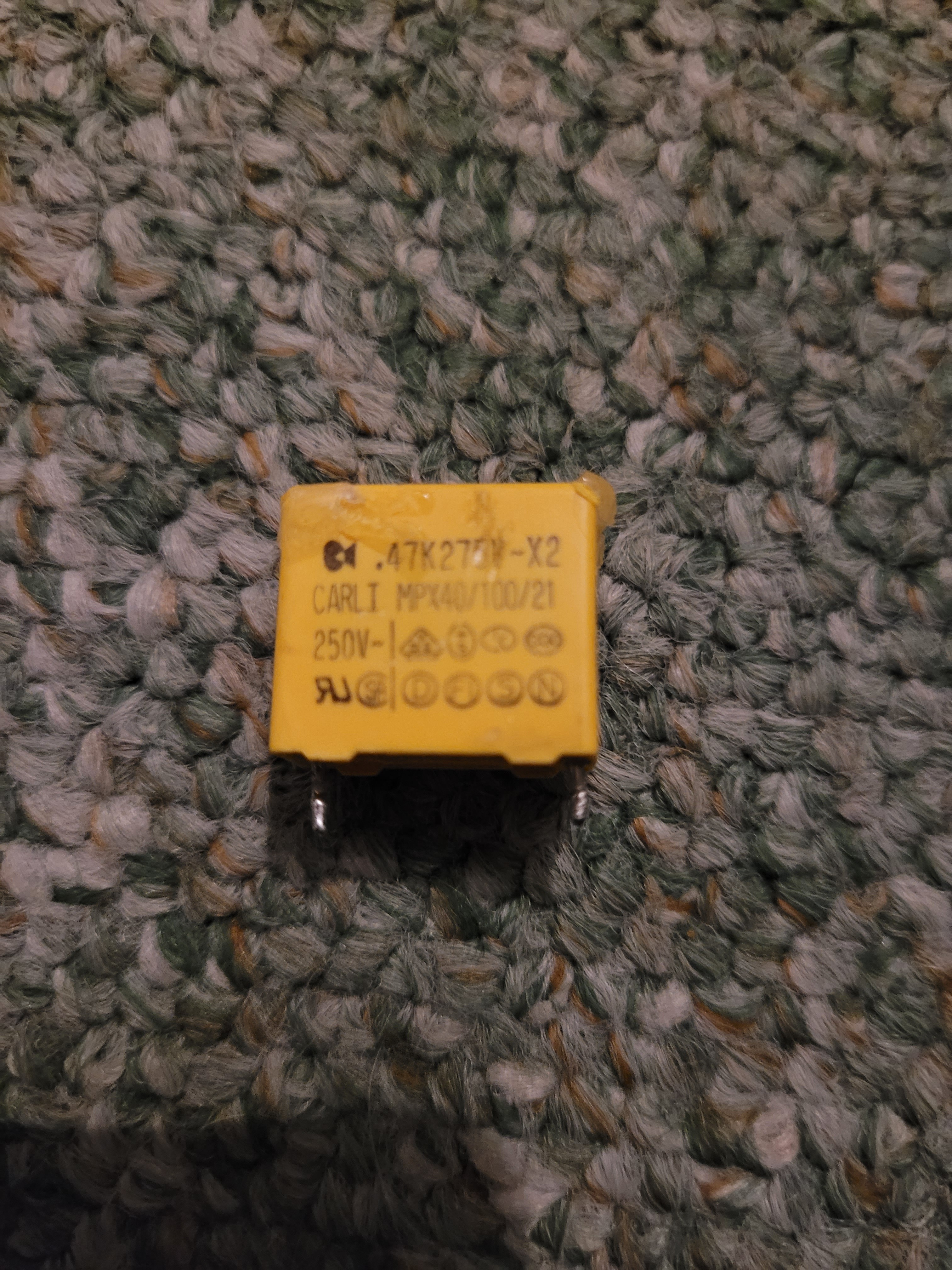
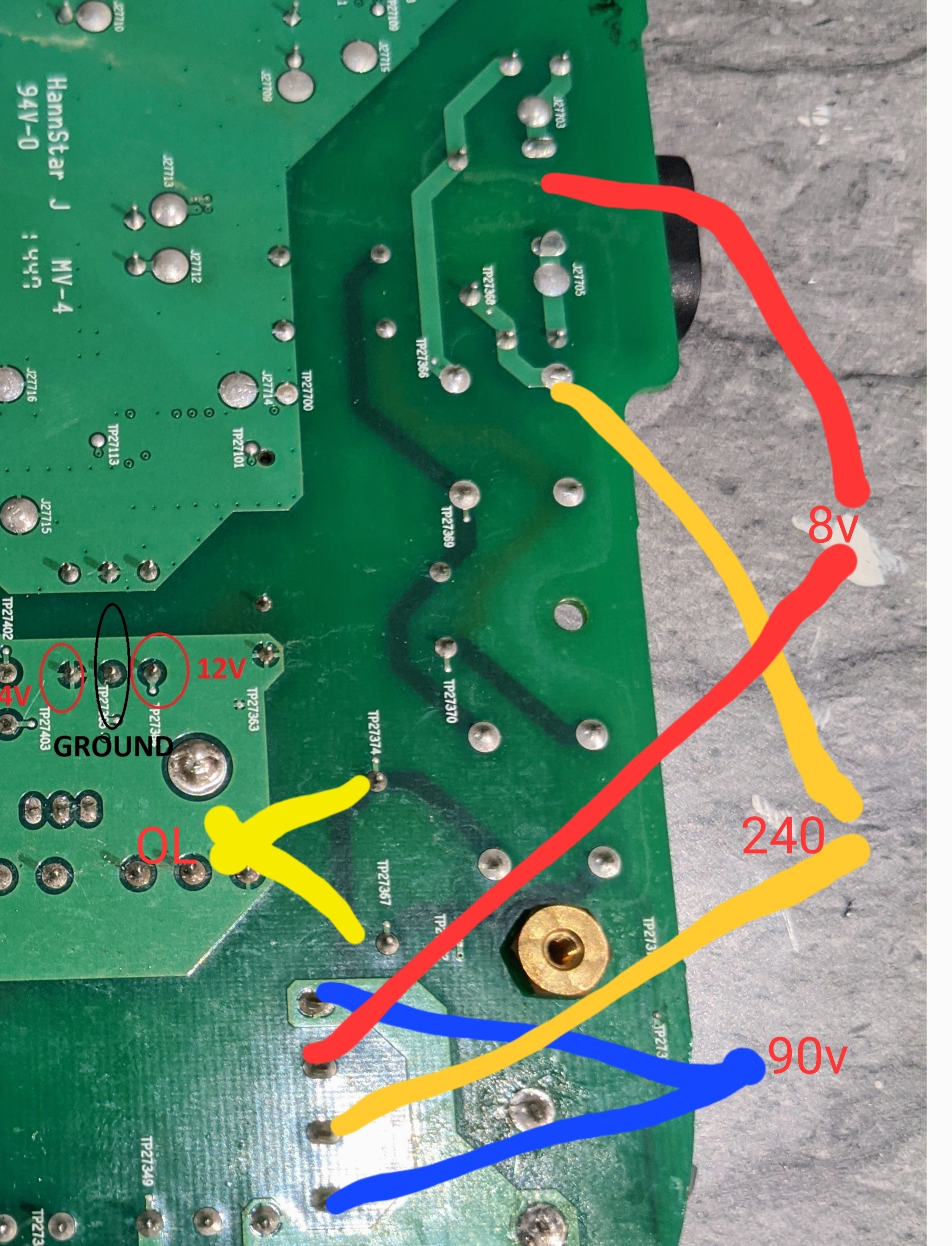
So we get a little further.. on the rectifier i have one ac leg at 240 and the other at 8. And dc output is 90v. So i measure back down the traces that u can see through the board and removed the mpx40 box cap. I get ol testing this. So it looks like when the reciifier blew it took this out and the fuse.i have some coming tomorrow hopefully. Ill report back once tested
I think that one is more of a suppression capacitor connected between live and neutral.
Isn´t there a inrush current limiting varistor on the opposite side of the fuse at the input socket? Maybe it´s that one that is blown?
I have replaced the Fuse and the rectifier and it words. Additionally i have replaced the five 820uF capacitors and two others. Now all works, but only the right middle speaker isnt working. I cant see any damages and all resistors etc working. Can you give me a notice where the damage can be?
Hi Dr_Phil.
Yes, if that resistor isn’t reading 4.5k, it will definitely affect the voltages. I would say though, it is rare in my experience for a failure like that. Resistors usually short out entirely, or blow open. Landing somewhere in the middle (like 12k) is unusual. It could be that the chip is actually ‘open’, but you are getting some other resistance measurement from the circuit itself.
I lost my info where I reverse engineered that part of the circuit, but the usual way that it works is that there is a reference voltage, and a feedback loop. A simple voltage divider is made on the output voltages, and that voltage is compared to the reference voltage. Often it is something like Vout=Vref*(1+V1/V2). Vref would depend on a chosen reference voltage elsewhere on the board, and the circuit designer chooses V1 and V2 to get the desired output. SO… If you are getting 12k instead of 4.5V, then your circuit is probably generating something like 5v/10v, instead of the required 12v/24v.
If you have a voltmeter, you can check what’s happening to the output voltages. Also, you would ideally test that bad chip after removing it from the circuit, but these are so small that it may be impossible to remove it without damaging it.
+1
Hi guys,
can someone tell me, what parts are the following and what I need to replace?
R27817
C27852
C27855
They are burned.
100ohm
0.1nF(maybe)
2.9nF(maybe)
Does it matter, how mich V the capacitor must have? And maybe means, i cannot measur up an SMD capacitor ?
+1
I tested the resistors in front of the Q27621, they are all ok. But D27721 has 0.5 V in the forward direction, the value keeps increasing in the opposite direction.Think it's broken. Does anyone know what replacement parts I need?
Great, i will try to measure the voltage and see if the result could guide me.
For what it’s worth, my pin1/3 on secondary side are also shorted. So either we both have the same problem or it’s supposed to be that way!
+1
Im find another short at tis part:
I guess there is written on:
E48 9558 or something like this.
It is blurred, so i cannot read ut as well.
Can someone help me and can tell me, what part it is?
+1
Hi folks, the volume on my box is very low. I've already checked the resistors and changed the APM4307... but it's still very quiet.How do I recognize a defective transistor?And could someone tell me how big the capacitor C27861 is or which diode D27706 it is or how I can check,if the diode is defective?
Page 8 / 9
Enter your username or e-mail address. We'll send you an e-mail with instructions to reset your password.