Hi
Play:5, manufacturing date sometime around 2009, is completely dead. No light in LED.
Found several cases of this online, but no solutions.
Does anyone have any knowledge about the problem, og better yet, schematics..
I mainly suspect problem in switch mode power supply. Have only done very basic measuring, but I find 220VAC on primary side, no power on secondary side. I think about ordering a mosfet, and/or a diode I suspect, but if I had schematics I could do some more pinpointing..

This topic has been closed for further comments. You can use the search bar to find a similar topic, or create a new one by clicking Create Topic at the top of the page.
Page 7 / 9
Hi All,
I’m trying to revive my Sonos Play 5 Gen1. After coming back from Holiday I plugged in the speaker and got a short circuit for some reason. Both Play 5’s I have are on the same circuit. One of them still working the other dead.
After reading this topic, i opened up the broken one and saw a crack in the SCK-054 en the fuse was blown. After I temporary replaced the fuse the main curcuite got blown again. so started to investigate and bumped on the Bridge Recitifier which is s KBU606 look like there is a short there. Not sure why this failed.
So no I need to replace the KBU606 unfortunately this part is EOL so cannot get the same any reccomendations for a replacement? I Have 2x GBU606 laying but not sure if they will work also the GBU606 is half the thickness of the KBU606.
Also need to replace the SCK-054 which is also EOL looking at ditributors within the region en they don’t seem to have the TKD also so not sure what to replace it with. I normally by from Reichelt in NL.
All the help appreciated as I’m hoping to get it fixed.
Cheers,
Hemant
Hi there,
My sonos play 5 power board had some overvoltage and some parts are blown.
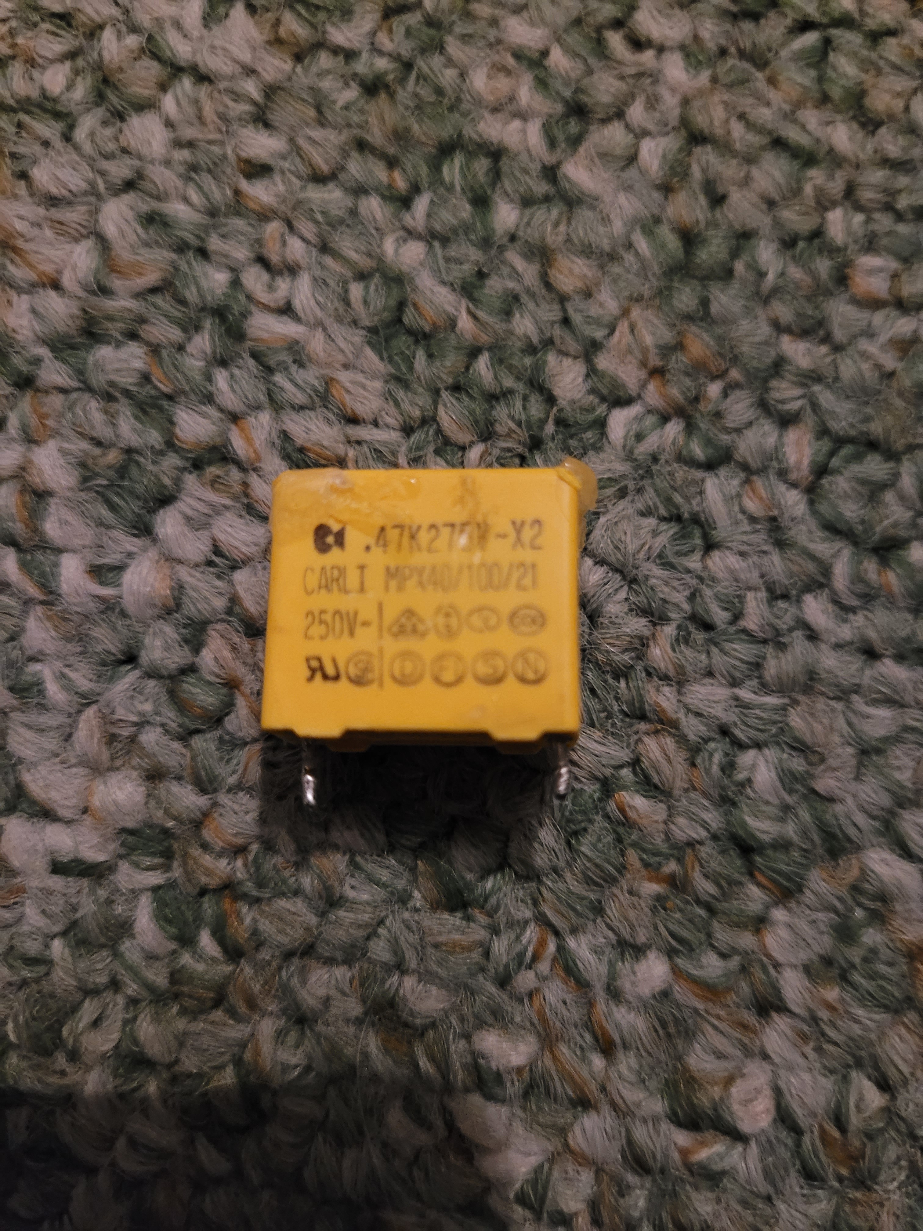
I managed to bring it back to life bij mounting a new PCB fuse3.15A and 2 capacitors 47K275V-X2
2 other components are broken and i cant determine what type they where.
Its about TH27700 at the inlet AC current side, i asume this is a NTC or PTC.
Also MOV27700 is broken, this should be a varistor after the first filter coils.
Does anyone know the partnumbers of these 2 components? You would realy help me out.
Thnx a lot!
The MOV27700 varistor is marked “TVR14471*”. TH27700 is an NTC thermistor “SCK 054”.
Good luck!
Thanx a lot Tim! Tomorrow i!ll go shopping ;-)

Can someone tell me the value of resistor R27842? Looks like it starts with “01..” but can’t be sure and I definitely can’t make out the last digit. It’s reading open. I think I scraped off some of the markings trying to get the glue off of it.
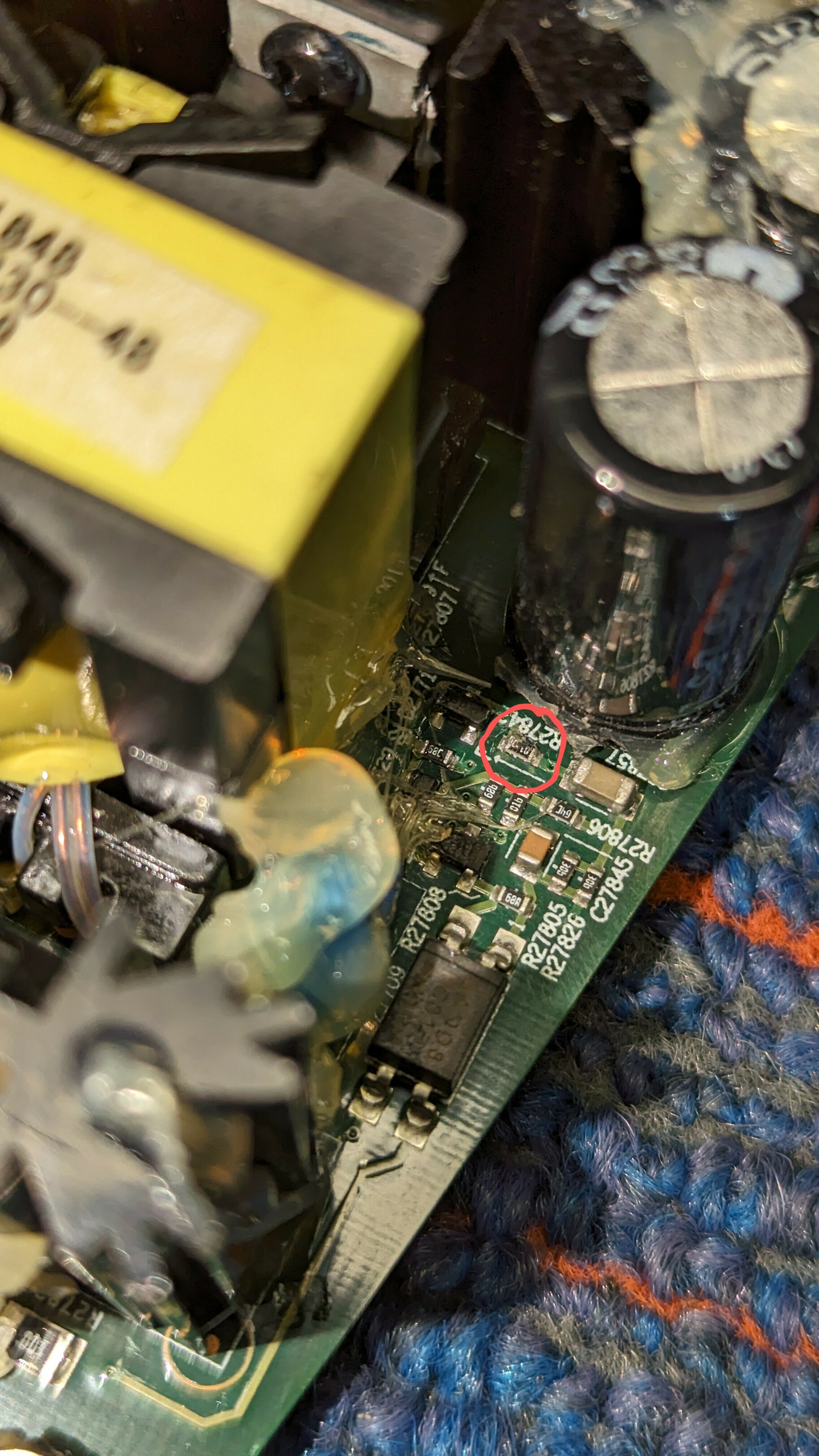
Just wanted to report back with another SUCCESS. My symptom was a slow blinking white light upon power up. This 1k ohm resistor was my problem.
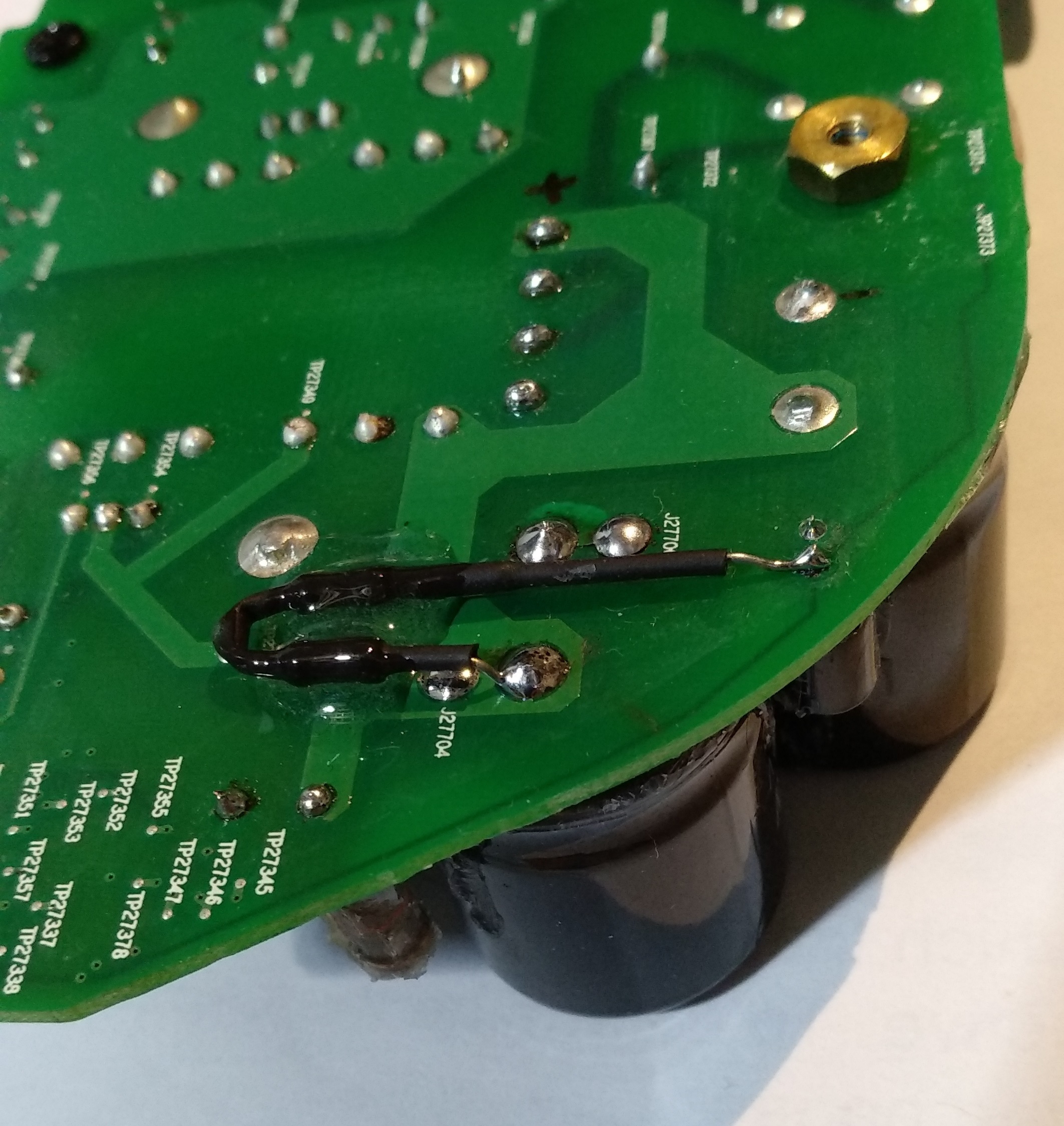
On the bottom side of the board are two points labeled with a TPxxxxx number (are these Test Points?) that are on either side of this resistor, and much easier to access than trying to squeeze into this space with a larger resistor. I removed the dead 1k ohm 0603 SMD resistor from the board and soldered an old carbon film resistor I had laying around from my old college lab days (class of ‘89) across those “test points” on the back side.
Powered up, found my network right away, and it’s back to making music. Thanks to everyone in this thread. All of the posts helped me track this down and fix it.
Can you please show me the points you mean? I have the same problem. Thanks
For me, both mids and highs were also without function. I replaced all the capacitors, after that no more problems.
hi yer its 240.. .hmmm thats weird. ill have to recheck. i wonder if theres an issue in one of the other layers
 +1
+1
Hi guys,
can someone tell me, what parts are the following and what I need to replace?
R27817
C27852
C27855
They are burned.
100ohm
0.1nF(maybe)
2.9nF(maybe)
So what does it mean "maybe"? Can't I measure up an SMD capacitor or what?
I should have taken a picture before I put it back together. Sorry! But if you flip that board over and post a pic of that area, I can point to what I mean.
If you hold a strong light up to the board you can follow the trace where that resistor is located, and you'll see two points of light shining through on either side of the resistor. Those points have a small solder bump on the back side. That's where I connected my replacement resistor.
This only works if it's that exact resistor that's dead.
Hello, thanks for the picture.
I have-it fixed finally but I do not know the cause. Here it is in words and pictures:
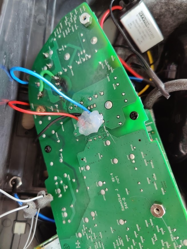
First, small cap (C27854) is not charging from the AC side, those are probably discharge resistors to the remaining capacity in the filtering caps. It’s another mechanism I could not figure out. The C27854 is providing power to the ICE2QS02 driver chip. It goes thru all those small diodes and caps on the edge of the board. The normal behavior on the voltage for C27854 is that is charging up to around 20V slowly and then ( some of those diodes and transistors do that) turns on the power on the ICE2QS02.
Once the chip is starting the voltage is self sustaining to around 13 V, I do not understand from where, maybe from the fly back transformer winding itself.
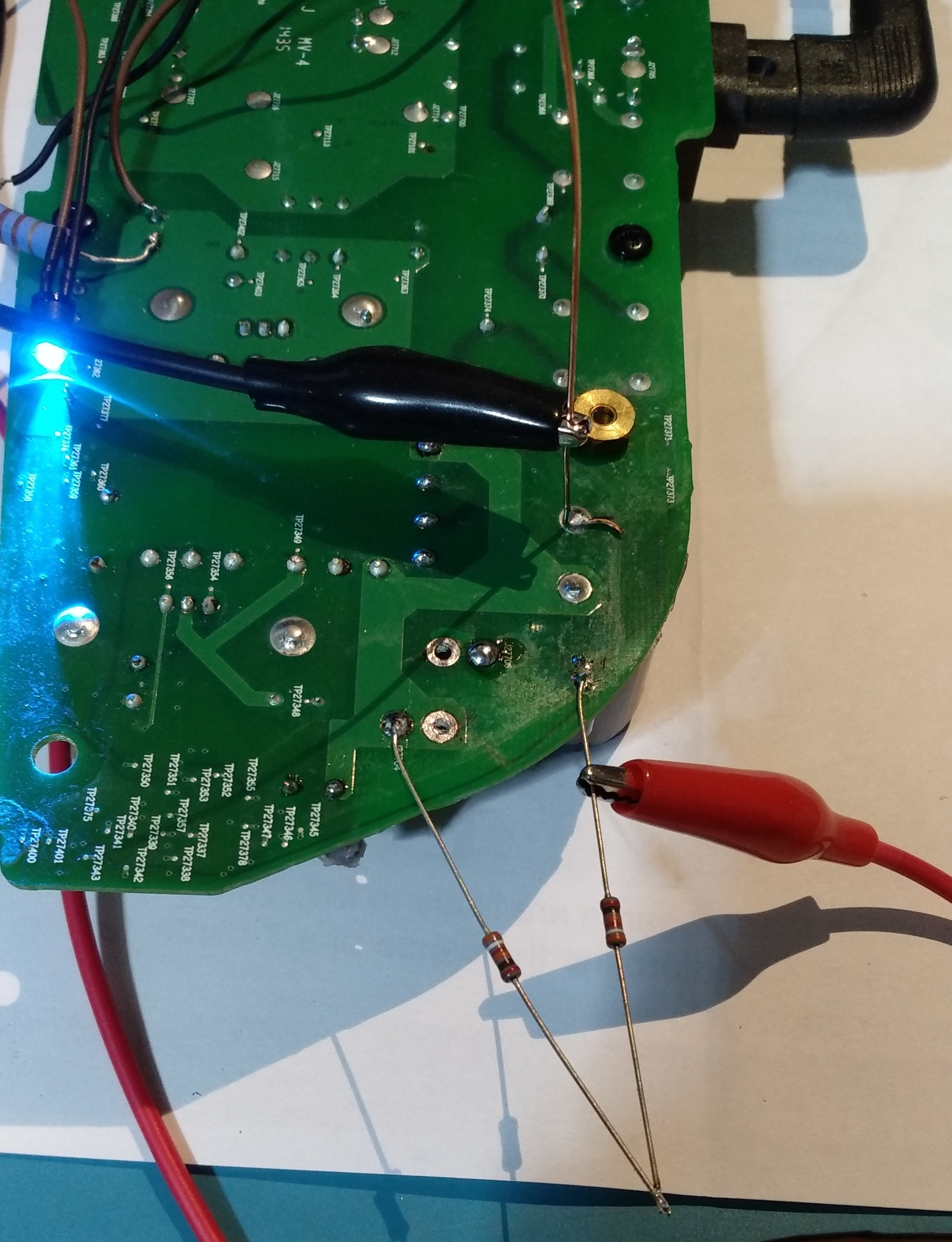
So for me the challenge was to produce the charging of the C27854 up to 20 to start up the IC. I did this by putting 2 390Kohm from the + on the big caps. I monitor the voltage and it’s ramping up slow, like a second or two. After it reaches 20V the IC starts and it self sustain to 13V. It’s 3 days already and still works! meaning there is no other fail. There was no problem in the fuse or rectifier, nothing burned. As you can see the LED turns on with the 2 resistors soldered. This is the story of this fix.

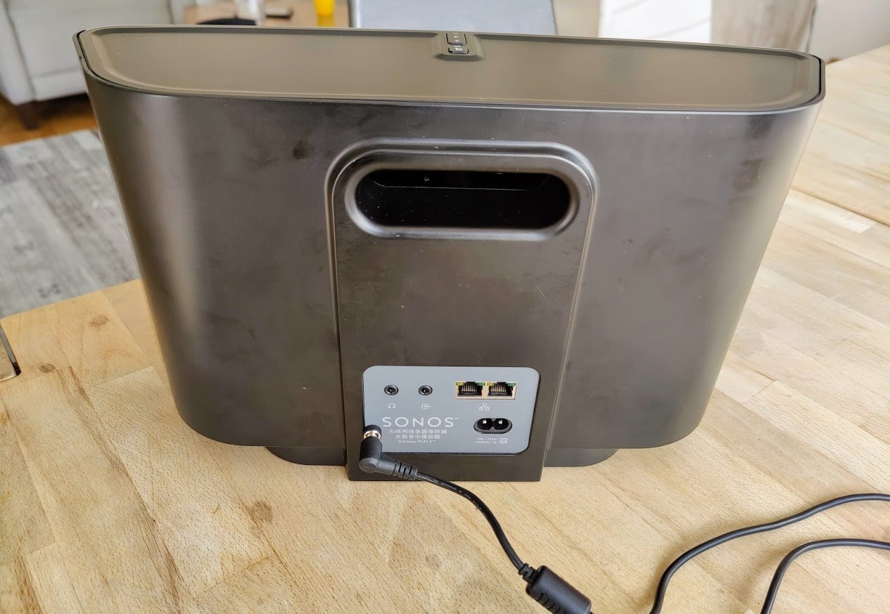
My Play:5 working again. If nothing helps you can power it with an external adapter.
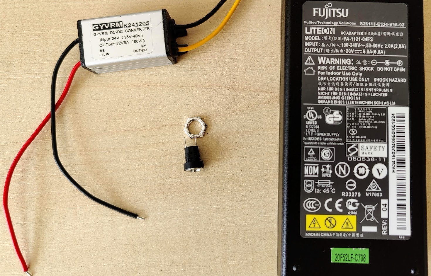
My setup:
- A laptop power adapter (20V - 6A)
- DC-DC converter (24-12V)
- DC connector (female)
The power is enough for max volume and there is no problem.
Thanks for the advice.
You beat me to it by a few hours! Nice job!
I just repaired mine too. I ordered a 24V/4A power supply very cheap on AMazon… $18CAD https://www.amazon.ca/gp/product/B08NYHM4J9/ref=ppx_yo_dt_b_asin_title_o00_s00?ie=UTF8&psc=1 . I chose this one because it was 250 grams, approximately 95 watts, and the size seemed like it would fit -inside- the case.
I had a few DC-DC converters on hand like this: https://www.amazon.ca/gp/product/B07Y88RTXJ/ref=ppx_yo_dt_b_search_asin_title?ie=UTF8&psc=1
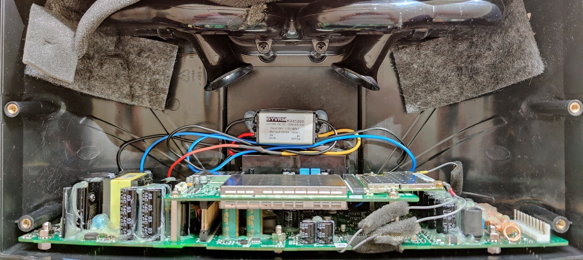
I was fortunately able to fit everything inside the case. I piggybacked the 120V supply to the AC-DC supply from the existing socket, and connected my DC-DC converter at the triple inductor like I had suggested a week or so ago. I opened the power supply case, removed the existing wires, and soldered it all in directly. I had to trim the two bass reflex ports about an inch, and was able to position the brick just below those centered between the two mid speakers at the back of the case. I wrapped the PS brick it in a sheet of foam to avoid vibration. It’s a snug fit, but everything went together perfectly. There is no vibration, and I can’t tell the sound difference between this and an unmodified speaker.
Can someone tell me the value of resistor R27842? Looks like it starts with “01..” but can’t be sure and I definitely can’t make out the last digit. It’s reading open. I think I scraped off some of the markings trying to get the glue off of it.
R27842 - 01b - 1kohm - 1000 ohm
Thanks VERY much!
JesperBandersen,
SONOS does not support field service. Schematics are not published, but you may be able to find partial schematics generated by users. (I am not aware of any)
SONOS does not support field service. Schematics are not published, but you may be able to find partial schematics generated by users. (I am not aware of any)
Actually mine had the mains fuse open and one diode in the mains side rectifier shorted.
Power mosfet and secondary rectifiers were ok.
I'll check the cheapo capacitors with an ESR meter in the evening.
Everything in this unit is very well glued, no wonder repairing is expensive 🙂
Power mosfet and secondary rectifiers were ok.
I'll check the cheapo capacitors with an ESR meter in the evening.
Everything in this unit is very well glued, no wonder repairing is expensive 🙂
Cheapo caps were within specs and at least unit powers up now.
Seems unit needs to be connected via ethernet or some link thing...complicated (I would have hoped for WLAN or BT)
I will try to arrange that and test it. We will then see if this 3€ repair did the trick 😉
Seems unit needs to be connected via ethernet or some link thing...complicated (I would have hoped for WLAN or BT)
I will try to arrange that and test it. We will then see if this 3€ repair did the trick 😉
@jlithen - I think I'm having the same issue - a few questions if you don't mind:
1. I don't see an internal fuse - do you mean the power cable fuse?
2. Which diode exactly was shot for you?
Thanks!
1. I don't see an internal fuse - do you mean the power cable fuse?
2. Which diode exactly was shot for you?
Thanks!
1. Fuse is close to mains connector. Red cylindrical one I'd say. Maybe it was 3.15AT??? Not sure.
Measure every component in series with line voltage if you're unsure which one is a fuse.
2. Rectifier on the mains voltage side. There is only one rectifier. Black with 4 feet.
Sorry but if you do not recognize those components you may need to study some more electronics before repairing.
In fact you better measure capacitors and switching FET before you attempt to power it up.
Check as much as possible ...and preferably power it up with current limiting.
Some components cause lots of damage if unit is powered up with them blown or shorted.
Hi, it's me again. Since my first 2 play 5 are running now I have another problem. Can anyone tell me which component is in the picture? I can't find anything about it on the internet.
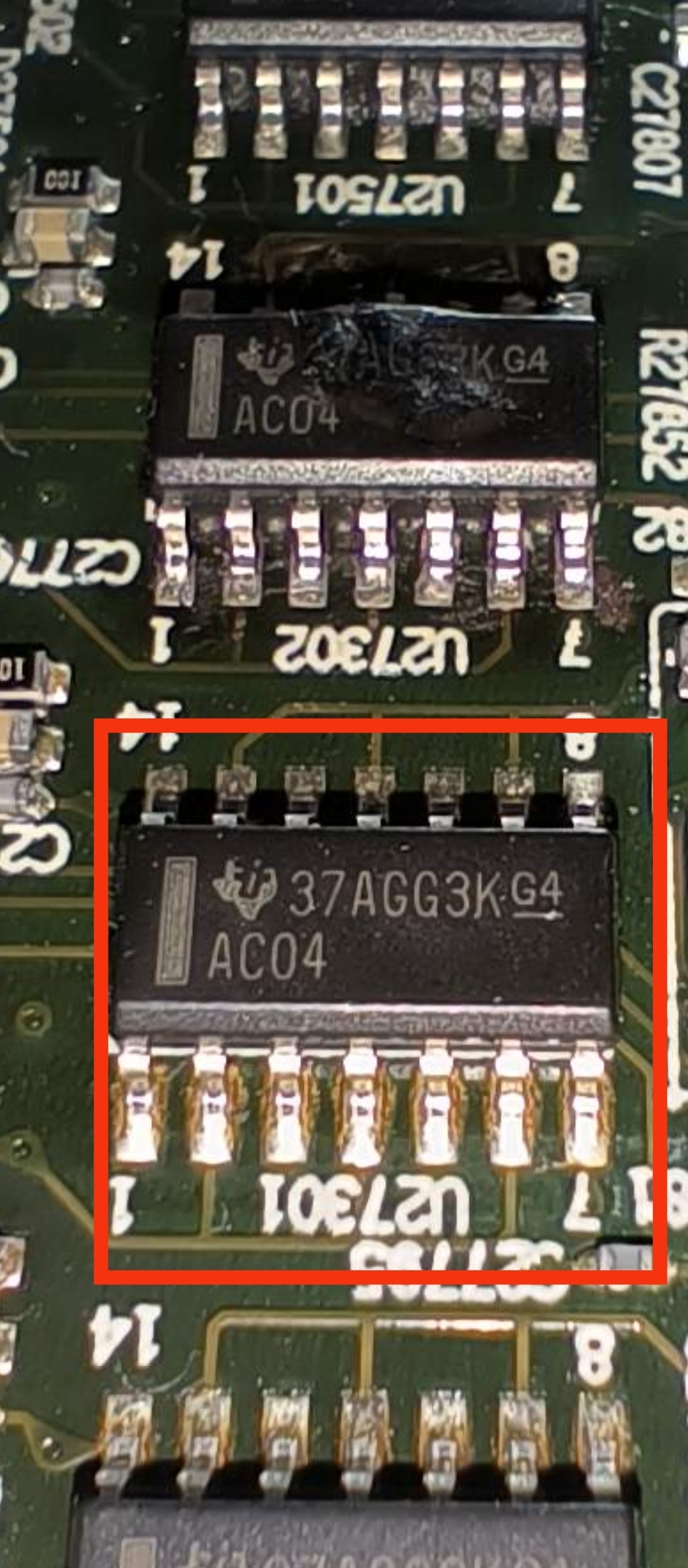
Thanks!
Exact same symptoms. Just desoldered the fuse and rectifier. Fuse is blown and measuring the rectifier, it seems that one of the diodes has failed. Will be picking up spareparts tomorrow - crossing my fingers that it works!
But someone should confiscate the hot glue gun from the workers at the assembly-line! Damn :)
/Dennis
My Play:5 is suffering the same issue, checked the fuse and the rectifier, the ac side of the rectifier is showing signs of a diode short circuit and the fuse has blown. Parts on order, wish me luck.
Hello, thanks for the picture.
I have-it fixed finally but I do not know the cause. Here it is in words and pictures:
First, small cap (C27854) is not charging from the AC side, those are probably discharge resistors to the remaining capacity in the filtering caps. It’s another mechanism I could not figure out. The C27854 is providing power to the ICE2QS02 driver chip. It goes thru all those small diodes and caps on the edge of the board. The normal behavior on the voltage for C27854 is that is charging up to around 20V slowly and then ( some of those diodes and transistors do that) turns on the power on the ICE2QS02.
Once the chip is starting the voltage is self sustaining to around 13 V, I do not understand from where, maybe from the fly back transformer winding itself.
So for me the challenge was to produce the charging of the C27854 up to 20 to start up the IC. I did this by putting 2 390Kohm from the + on the big caps. I monitor the voltage and it’s ramping up slow, like a second or two. After it reaches 20V the IC starts and it self sustain to 13V. It’s 3 days already and still works! meaning there is no other fail. There was no problem in the fuse or rectifier, nothing burned. As you can see the LED turns on with the 2 resistors soldered. This is the story of this fix.
Well done dvd4me!
The 2QS02G needs some power to start the switching function, but it seems to work quite well with a range of voltages. I think that this is why it was driven with just a simple voltage divider circuit.
You inspired me to dust off an old non-functioning board. Unfortunately I have some other kind of problem. I’ll describe it here, in case someone can help me.
For me the voltage on that pin grows slowly, then falls to 5-10v or so, then starts climbing again and repeating the cycle. Even when I inject 13V to that spot from a bench supply it doesn’t help.
Typical SMPS supplies switches a high voltage via a MOSFET into the primary side of the transformer. That switching is controlled by the 2QS02G. I tried replacing it with no luck, and couldn’t find anything else off around it. What I did find though, was that the high voltage was 160V. I measured it as marked in the attached image. This is a problem for me, since when I measured a known good device, the voltage was 274V. The 160V seems to just be the rectified AC, and is not boosted to 274. I can’t figure out the mechanism that is causing the 274V to be produced, so am stumped. Any ideas?
Hello,
From what I understand now, your board does not start, when the voltage on 2QS02 goes up to 20 and the chip powers on, there must be an error that makes the chip to shut down immediately, thus not self-sustaining to 13V. The power on the caps is simple rectified by the bridge, try to measure on another type of switch power supply. Me I got-it from 110V AC so it goes around that 160V I believe ( I did not wrote down the value. Yours if it is 220VAC so it might be 274 or a bit higher rectified. Maybe your rectifier bridge is broken ( one diode is interrupted, so it’s half of the voltage. This driver chip checks for the voltage, locks for undervoltage. The rectifier is your problem. Check for that.
Regards
Can someone tell me the value of resistor R27842? Looks like it starts with “01..” but can’t be sure and I definitely can’t make out the last digit. It’s reading open. I think I scraped off some of the markings trying to get the glue off of it.
I've just closed mine after repair... But I will probably receive another one in a few weeks for reparation; I will look for the number and also try to measure it. I hope you can wait that long ...
This looks a great thread
I’ve been doing repairs on play 3’s and again it’s rectifier caps and fuses to blame ! Although there was a hole through the PCB on the play 3
Going to try and repair 2 play5 and 2 play 1s
Wish me luck
I find next day with RS is reliable
Thanks
Ian
I’ve been doing repairs on play 3’s and again it’s rectifier caps and fuses to blame ! Although there was a hole through the PCB on the play 3
Going to try and repair 2 play5 and 2 play 1s
Wish me luck
I find next day with RS is reliable
Thanks
Ian
My play:5 broke down about 6 months ago, and i fixed it bye changing the KBU606 and the 3.15AT fuse, as mentioned here. But now it broke down again, and i assumed the same fix would do the trick - but no - this time the rectifier&fuse are working as they should. Yet nothing happens when i plug it in. Anyone who's found another fix to the symptoms besides changing the rectifier&fuse?
Tried changing the Caps just after the rectifier ?
I could when the rectifier went it took the Caps out just before the fuse blew ?
I could when the rectifier went it took the Caps out just before the fuse blew ?
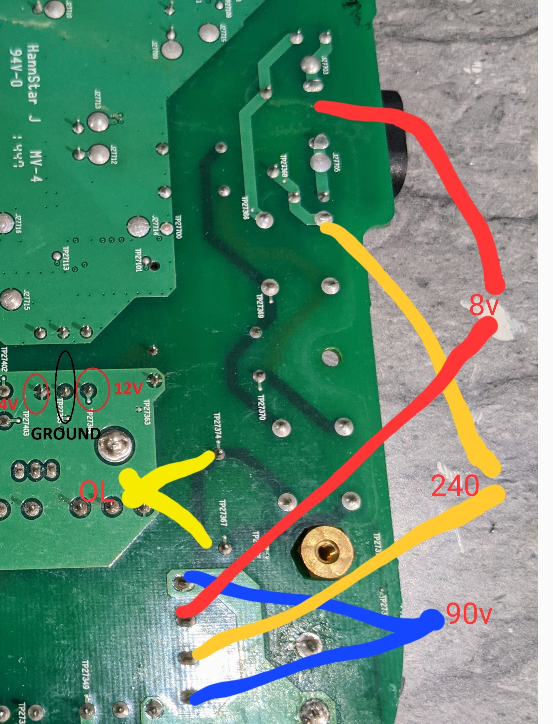
So we get a little further.. on the rectifier i have one ac leg at 240 and the other at 8. And dc output is 90v. So i measure back down the traces that u can see through the board and removed the mpx40 box cap. I get ol testing this. So it looks like when the reciifier blew it took this out and the fuse.i have some coming tomorrow hopefully. Ill report back once tested
Hi Folks, First post here :) I’ve been lurking on this thread as I’ve purchased a few used Play 5’s over the last few weeks. Most of them work great, except a couple needed repairs, so I thought I’d pass on what I’ve learned by applying responses from previous posts.
Symptom 1: Low volume from both midrange speakers and distorted bass from woofer.
Solution 1: All of the 820uF caps of the output amps (6 total) were defective (bulging tops and low capacitance measured on all of them). Additionally, the 470uF filter caps on the output stage of the midrange amps we also defective (bulging tops as well). Replaced all 8 caps, midrange and woofer issues resolved.
Symptom 2: Wireless ethernet not working (speaker could not be found after a reset), but wired ethernet works properly. Two Play 5’s exhibiting this fault.
Solution 2: Removed the wireless adapter card from the socket, cleaned the edge connector fingers with flux remover and cleaned the socket pins as well. Reinstalled wireless adapter. Both are now functional with wireless ethernet.
Hope these two fixes helps others with similar issues.
Fooo
Page 7 / 9
Enter your username or e-mail address. We'll send you an e-mail with instructions to reset your password.