Hi
Play:5, manufacturing date sometime around 2009, is completely dead. No light in LED.
Found several cases of this online, but no solutions.
Does anyone have any knowledge about the problem, og better yet, schematics..
I mainly suspect problem in switch mode power supply. Have only done very basic measuring, but I find 220VAC on primary side, no power on secondary side. I think about ordering a mosfet, and/or a diode I suspect, but if I had schematics I could do some more pinpointing..

This topic has been closed for further comments. You can use the search bar to find a similar topic, or create a new one by clicking Create Topic at the top of the page.
Page 6 / 9

Here is the best I’ve found on debugging Sonos Play:5 hardware issues:
https://sites.google.com/site/sonosdebug/power-topology
The author includes reverse-engineered information about jtag, serial port, connector, and the power supply (including a very helpful partial circuit diagram)!
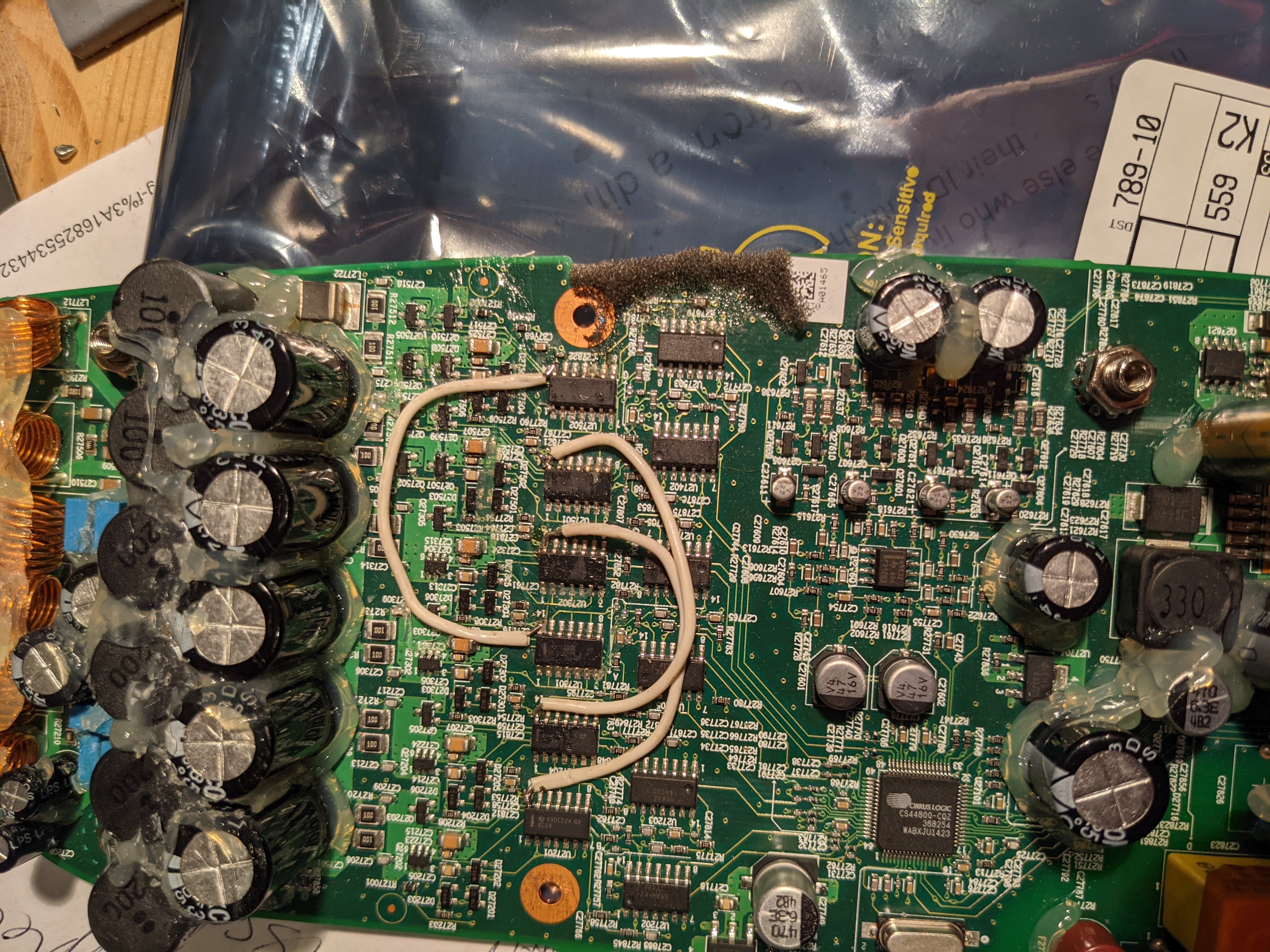
There is nothing about the actual power amp. I have seen a few of these go bad and had only marginal success fixing them. One finding I did have was that a unit with missing bass had some of the driver ICs not having power. It turned out that some of the internal traces had burned out between the driver chips. I jumpered all of the power pins of the 6 ICs together (and all of the grounds too, for good measure), and it solved the problem.
If you have NO sound from the amplifier, then check the biases identified on the schematic and make sure that all of them (12v, 3.3V, 11.1V, 5V) are working.
Hi Tim,
Is your play 5 having issue of very soft volume? Then you jumpered the traces and that fixed it?
Hi. Sorry for the late response. I was locked out… Can't log in
The problem that I had was that of the 5 speakers, some were working and others were not. I found that some of the driver chips did not have power and was able to add power to them… after which it all worked again. Here is a picture of what I jumpered. I think that this was not the complete job… but you should get the idea from here.

Im going to piggyback onto this discussion to see if someone can help me out.
I have a Power supply issue with an issue on the switching side.
The unit has no power.
Replaced most of the power side caps, rectifier, fuse, FET IC Driver, FET, (Also smt 120K resistor near the rectifier was blown.)
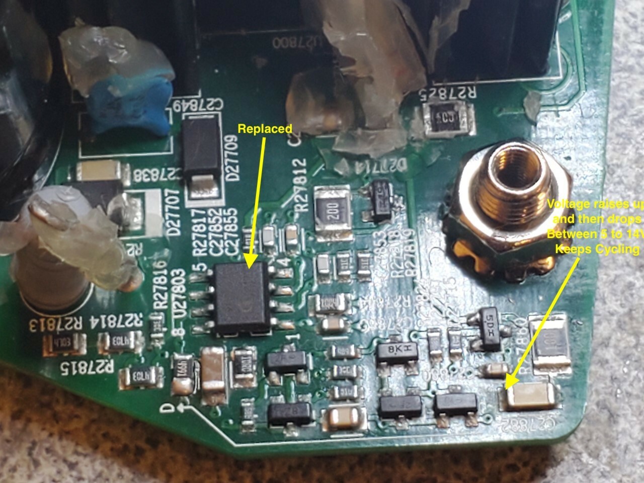
I feel like im close, but I have this problem where the voltage starts at 5v ramps up to 15v and then bumps back down to 5v to repeat the process. Thought maybe a diode, but I cant find it.
When i remove the little 25v 100uf Cap between the two big filtering caps, the fluctuation goes away. Still get no power though.
Any Thoughts?
Hi, all, got a great deal of help from the posts in here so I want to chip in a bit.
My Play 5 1st gen suddenly didn't start up properly. Lamp blinking white. Got the main PCB out and noticed that the the power was cycling every second. This could be measured on many places on the board but for example between pin 7 and 8 on the 2QS02G. There was also a small sound from the transformer at each cycle.
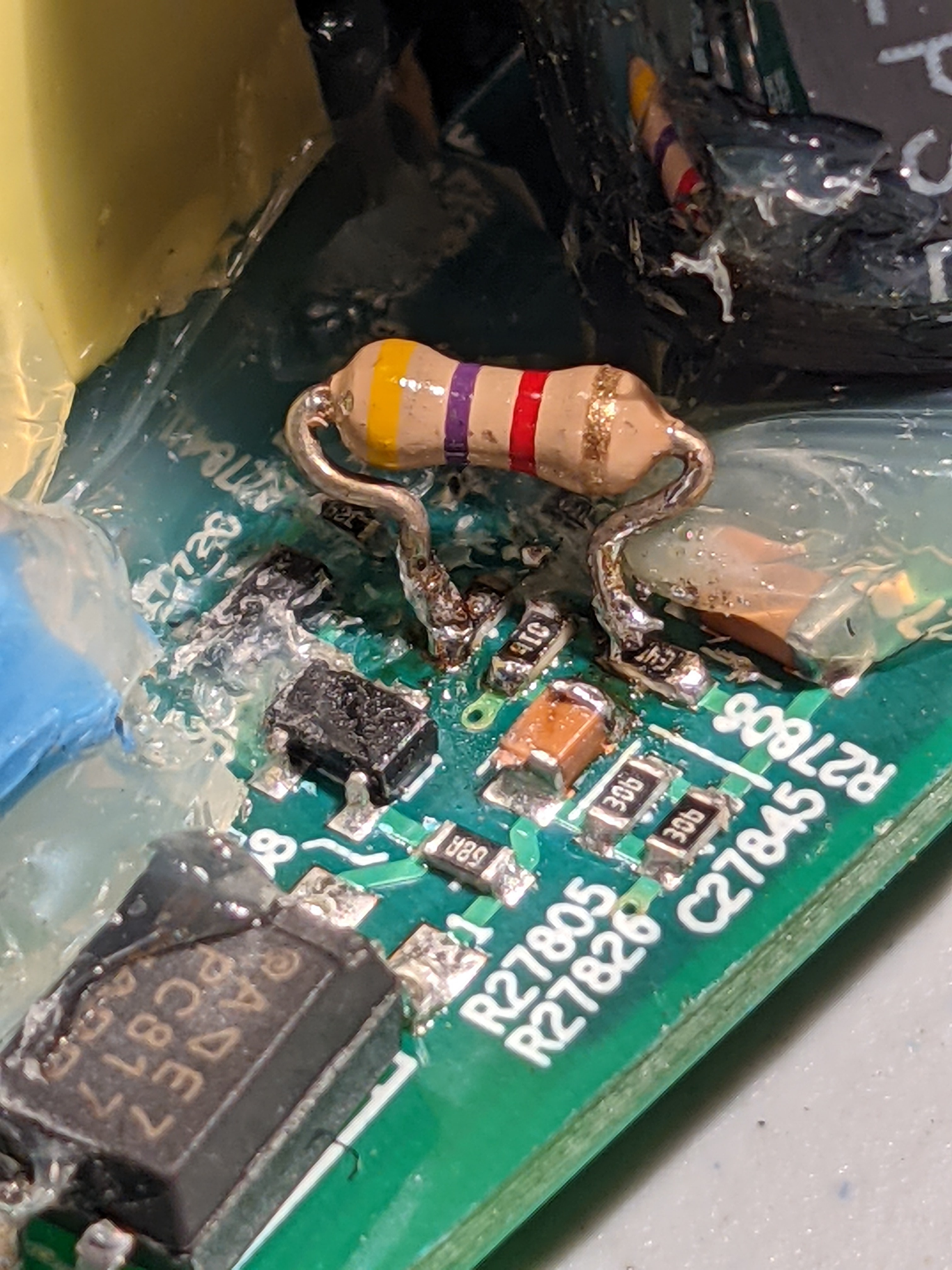
Thanks to page 3 here I could locate that the 10 Ohm resistor R27825 was broken. This resistor was hidden by a big heap of glue. I left it in place since it was broken and soldered a standard resistor over its legs. And the unit now powers on correctly.
A tip: when the speaker front has been removed you can take off the 4 5.5mm nuts of the top PCB and gently lift it up. Now its possible to leave this top board in place and not mess with the wifi antennas and such.
Im going to piggyback onto this discussion to see if someone can help me out.
I have a Power supply issue with an issue on the switching side.
The unit has no power.
Replaced most of the power side caps, rectifier, fuse, FET IC Driver, FET, (Also smt 120K resistor near the rectifier was blown.)
I feel like im close, but I have this problem where the voltage starts at 5v ramps up to 15v and then bumps back down to 5v to repeat the process. Thought maybe a diode, but I cant find it.
When i remove the little 25v 100uf Cap between the two big filtering caps, the fluctuation goes away. Still get no power though.
Any Thoughts?
Check the resistor R27825, this is 10Ohm I believe. Normally not visible due to the extensive glue on the board. I had a similar case where there was no power at all. I didn't check in detail but I think this resistor is part of a control loop. Another issue where replacing a single resistor restores services.
God news my sonos Play 5 sings
I have changed the small chip that controls the mosfet
2QS02G
I also changed the rectifier MBR20150TC, but I do not thing it was defect. I broke it during the removal. I had to take it out to read the type. And therefore had to install a new one.
also changed 5 pcs electrolytic capacitors 820uf 35V
Hello, I happen to have a Gen 1 with similar power issue, I see on your picture you changed the chip.
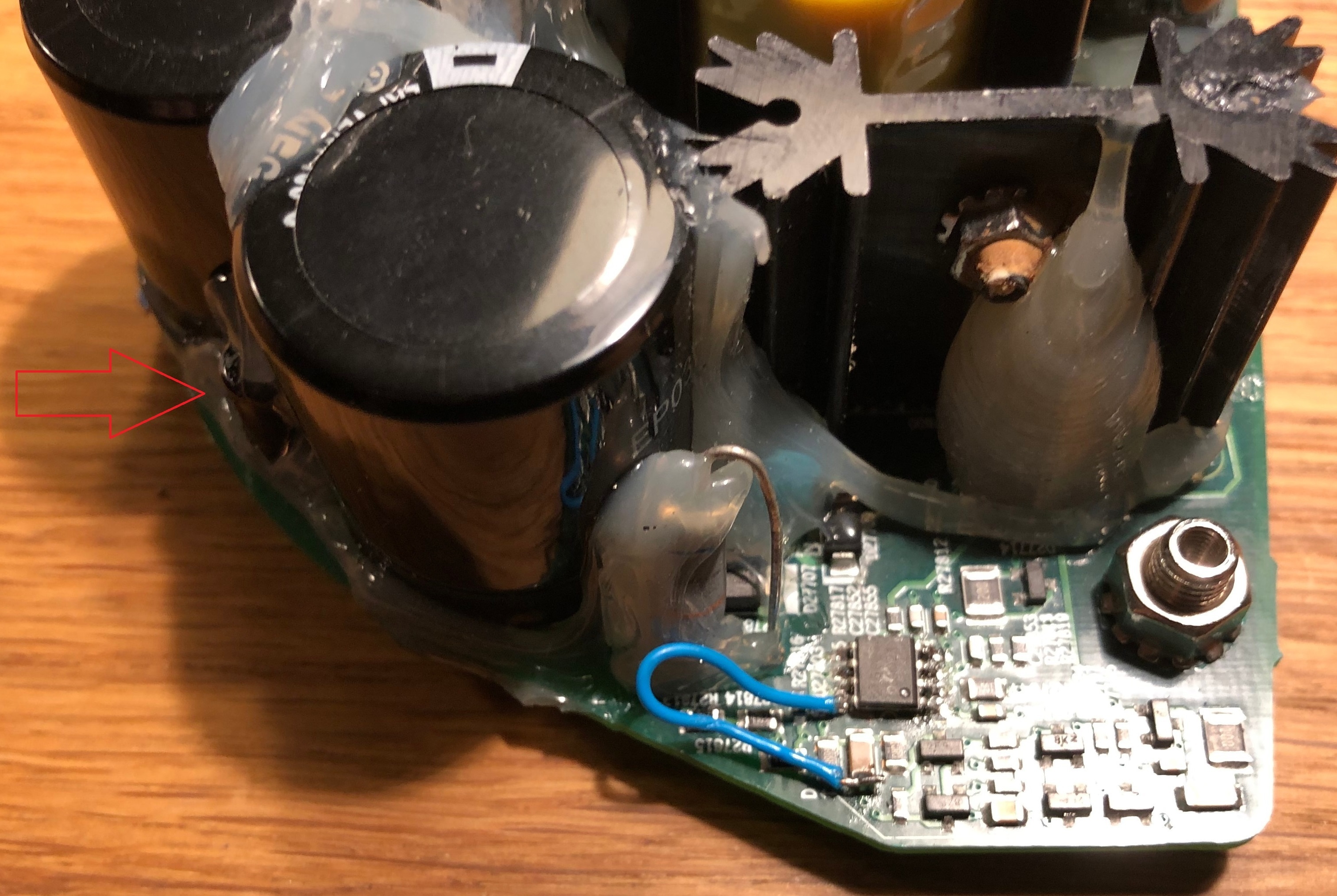
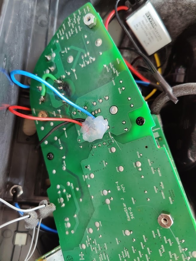
In my case there is no power on the pin 7 of the small driver IC. I cannot figure out from where it gets the power. I manually power the chip with an external 12 V on that capacitor you solder the blue wire. And the power gets back alive! But it’s not self sustaining and as soon as I remove the external Vcc for the IC it goes back to silence. There must be a component I cannot see on the pcb to supply power to the IC. The small cap 100uF 25V has a connection with the power of the driver IC but I cannot figure-it out. Any ideas? Thanks
Hello, thanks for the picture.
I have-it fixed finally but I do not know the cause. Here it is in words and pictures:
First, small cap (C27854) is not charging from the AC side, those are probably discharge resistors to the remaining capacity in the filtering caps. It’s another mechanism I could not figure out. The C27854 is providing power to the ICE2QS02 driver chip. It goes thru all those small diodes and caps on the edge of the board. The normal behavior on the voltage for C27854 is that is charging up to around 20V slowly and then ( some of those diodes and transistors do that) turns on the power on the ICE2QS02.
Once the chip is starting the voltage is self sustaining to around 13 V, I do not understand from where, maybe from the fly back transformer winding itself.
So for me the challenge was to produce the charging of the C27854 up to 20 to start up the IC. I did this by putting 2 390Kohm from the + on the big caps. I monitor the voltage and it’s ramping up slow, like a second or two. After it reaches 20V the IC starts and it self sustain to 13V. It’s 3 days already and still works! meaning there is no other fail. There was no problem in the fuse or rectifier, nothing burned. As you can see the LED turns on with the 2 resistors soldered. This is the story of this fix.
Well done dvd4me!
The 2QS02G needs some power to start the switching function, but it seems to work quite well with a range of voltages. I think that this is why it was driven with just a simple voltage divider circuit.
You inspired me to dust off an old non-functioning board. Unfortunately I have some other kind of problem. I’ll describe it here, in case someone can help me.
For me the voltage on that pin grows slowly, then falls to 5-10v or so, then starts climbing again and repeating the cycle. Even when I inject 13V to that spot from a bench supply it doesn’t help.
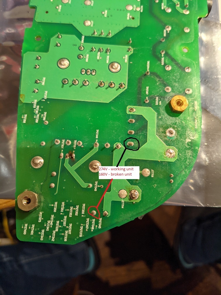
Typical SMPS supplies switches a high voltage via a MOSFET into the primary side of the transformer. That switching is controlled by the 2QS02G. I tried replacing it with no luck, and couldn’t find anything else off around it. What I did find though, was that the high voltage was 160V. I measured it as marked in the attached image. This is a problem for me, since when I measured a known good device, the voltage was 274V. The 160V seems to just be the rectified AC, and is not boosted to 274. I can’t figure out the mechanism that is causing the 274V to be produced, so am stumped. Any ideas?
Hello,
My play 5 Gen 1 is acting a bit strange. when i power the speaker up it is working fine. when i restart (unplug an replug) the play 5, to move it for example. it won’t boot up. no lights no sound.
if i wait a couple hours it will boot up again. can this be a capacitor fault or a thermistor somewhere?
I desoldered all the capacitors and measured them, they seem te be okay. (capacity measurement only, no ESR)
my voltages are similar to Anders J. Instead of 0V i get between 0-2 volts which should be 11-12 and 24V. so i think the problem should be somewhere on the HV side.
Since the speaker wont turn on for a while could this mean the capacitors have to be empty first?
(picture from Anders J.)
Hello, I believe we have similar related fail mode, the intermittent start up is related with the Vcc absence on pin 7 of the ICE2QS02 driver chip. It comes from somewhere I cannot see on the board. Since you have removed all the caps from under the glue, can you check if the small cap 100uf/25V (between the 2 big 400V caps) is connected to any of the high voltage rail? I suspect this small cap is the key to supply power to the driver IC. In my case the 2QS02 chip has no power on pin 7 and obviously it will not work.
If I power the IC externally with 12v then the power is fine. I have to figure out what is the intermittent component related to this failure.
Thanks
Here is the best I’ve found on debugging Sonos Play:5 hardware issues:
https://sites.google.com/site/sonosdebug/power-topology
The author includes reverse-engineered information about jtag, serial port, connector, and the power supply (including a very helpful partial circuit diagram)!
There is nothing about the actual power amp. I have seen a few of these go bad and had only marginal success fixing them. One finding I did have was that a unit with missing bass had some of the driver ICs not having power. It turned out that some of the internal traces had burned out between the driver chips. I jumpered all of the power pins of the 6 ICs together (and all of the grounds too, for good measure), and it solved the problem.
If you have NO sound from the amplifier, then check the biases identified on the schematic and make sure that all of them (12v, 3.3V, 11.1V, 5V) are working.
Hi Tim,
Is your play 5 having issue of very soft volume? Then you jumpered the traces and that fixed it?
Hi. Sorry for the late response. I was locked out… Can't log in
The problem that I had was that of the 5 speakers, some were working and others were not. I found that some of the driver chips did not have power and was able to add power to them… after which it all worked again. Here is a picture of what I jumpered. I think that this was not the complete job… but you should get the idea from here.
Thanks Tim. Unfortunately my play 5 issue is not the same issue. All the pins have 5V to it. Headphone out is working fine, just the all speakers have a very faint sound.
Faint sound at max volume? Check this.
Hello, first of all sorry for my bad English. I have the following problem, my play 5 gen1 only outputs sound over sub and high. Midrange is dead. I'm already disassembling the play5. You can't see faults with the eye. Which components are responsible for the center? I would be very grateful for tips.
God news my sonos Play 5 sings
I have changed the small chip that controls the mosfet
2QS02G
I also changed the rectifier MBR20150TC, but I do not thing it was defect. I broke it during the removal. I had to take it out to read the type. And therefore had to install a new one.
also changed 5 pcs electrolytic capacitors 820uf 35V
Hello, I happen to have a Gen 1 with similar power issue, I see on your picture you changed the chip.
In my case there is no power on the pin 7 of the small driver IC. I cannot figure out from where it gets the power. I manually power the chip with an external 12 V on that capacitor you solder the blue wire. And the power gets back alive! But it’s not self sustaining and as soon as I remove the external Vcc for the IC it goes back to silence. There must be a component I cannot see on the pcb to supply power to the IC. The small cap 100uF 25V has a connection with the power of the driver IC but I cannot figure-it out. Any ideas? Thanks

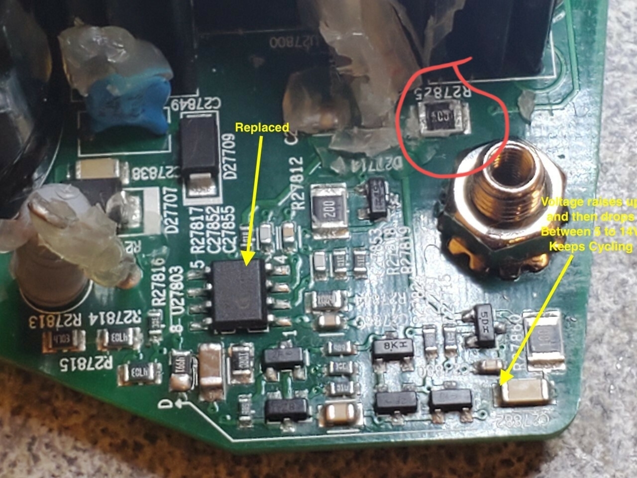
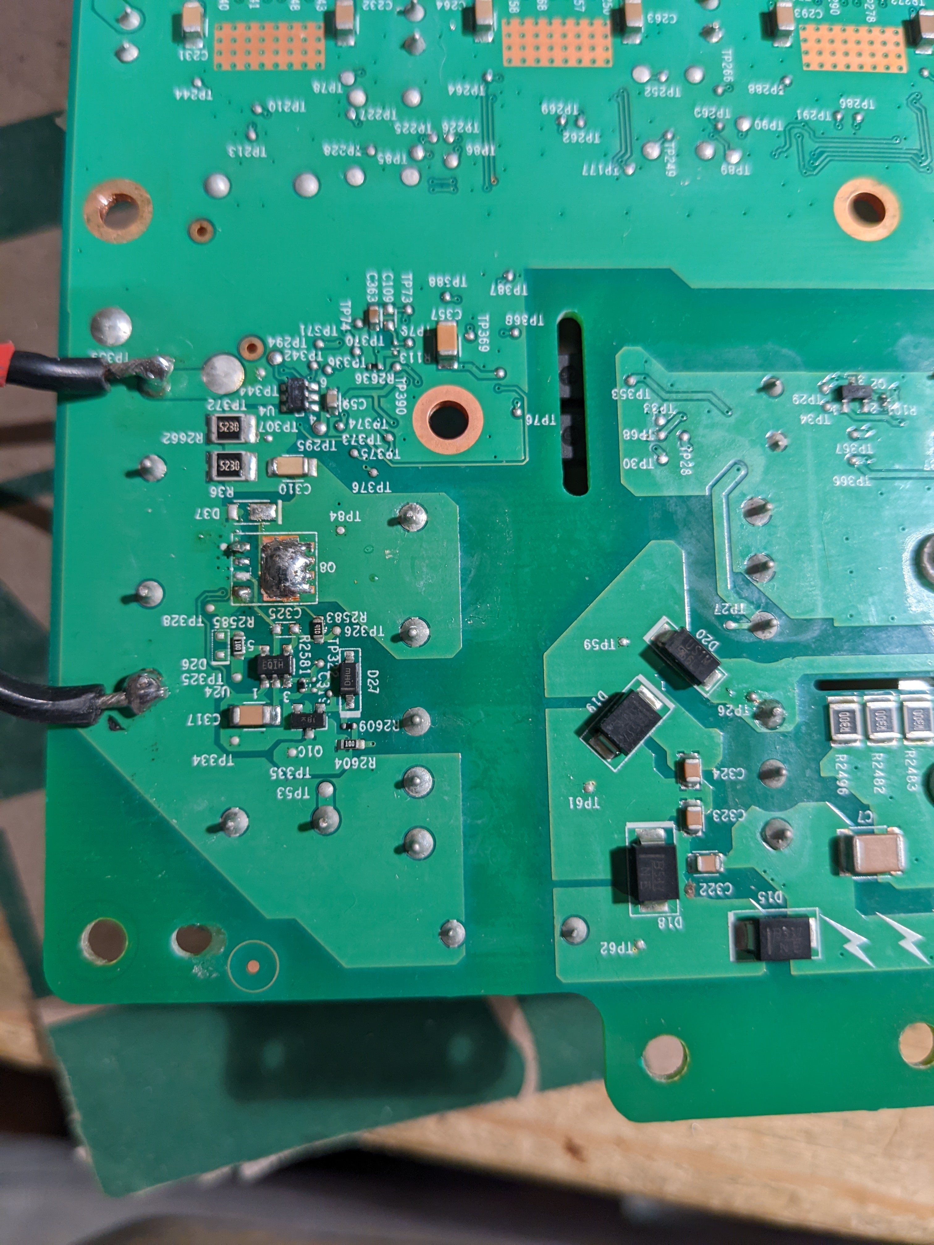
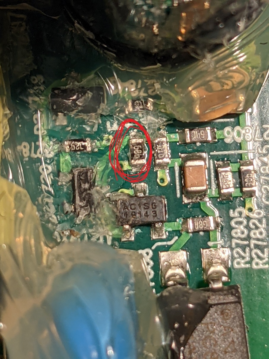
Check this resistor circled in red, R27825. Should be 10 Ohm. In one of my Play 5's it died. Another example of a cheap part killing an expensive speaker
Yep...that’s certainly an option…..I would just love the satisfaction of being able to repair it though. Its crappy that Sonos can’t provide component lists for discontinued products….even the circuit diagrams...really no reason 😌
They are going to be in trouble with the European Unions ‘right to repair’ laws…..
For devices designed around 15 years ago? I doubt it.
For all products they currently sell in Europe…..
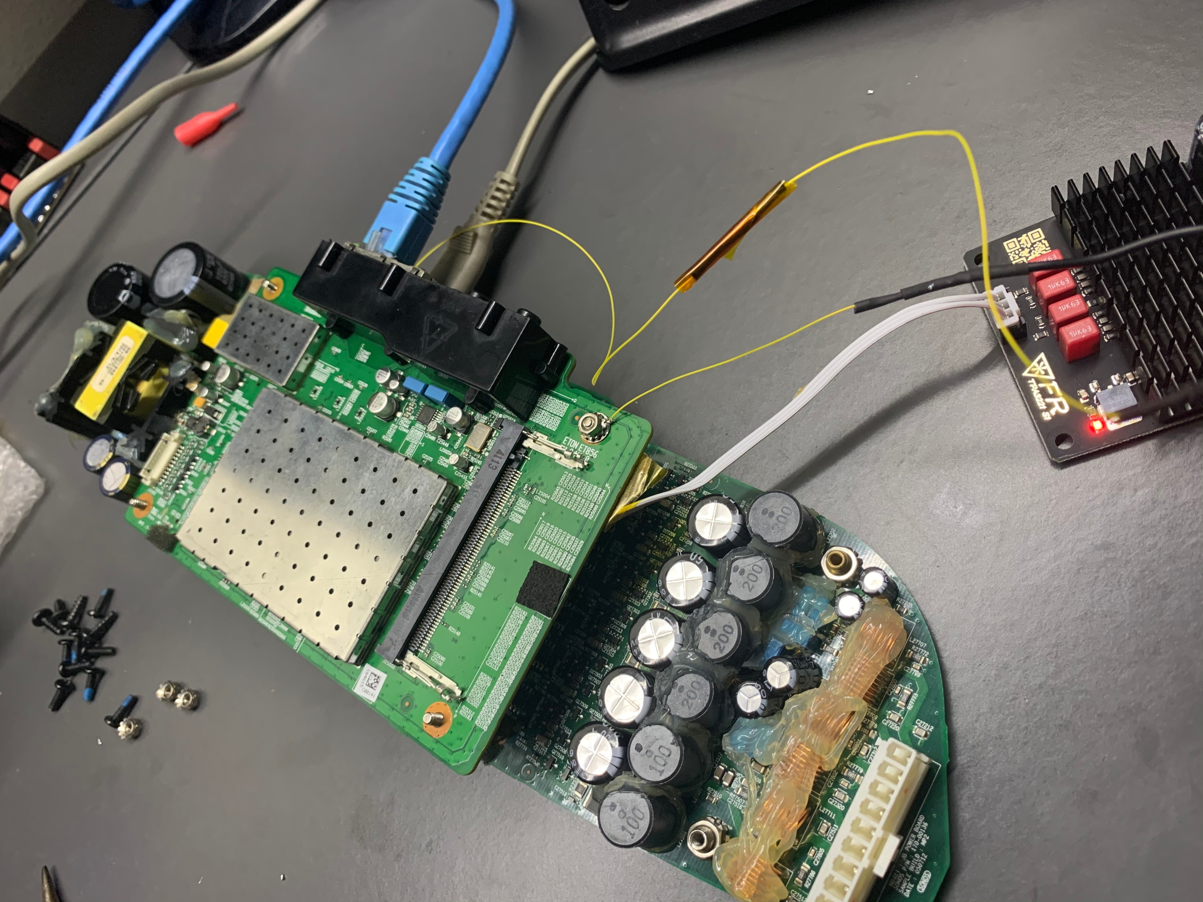
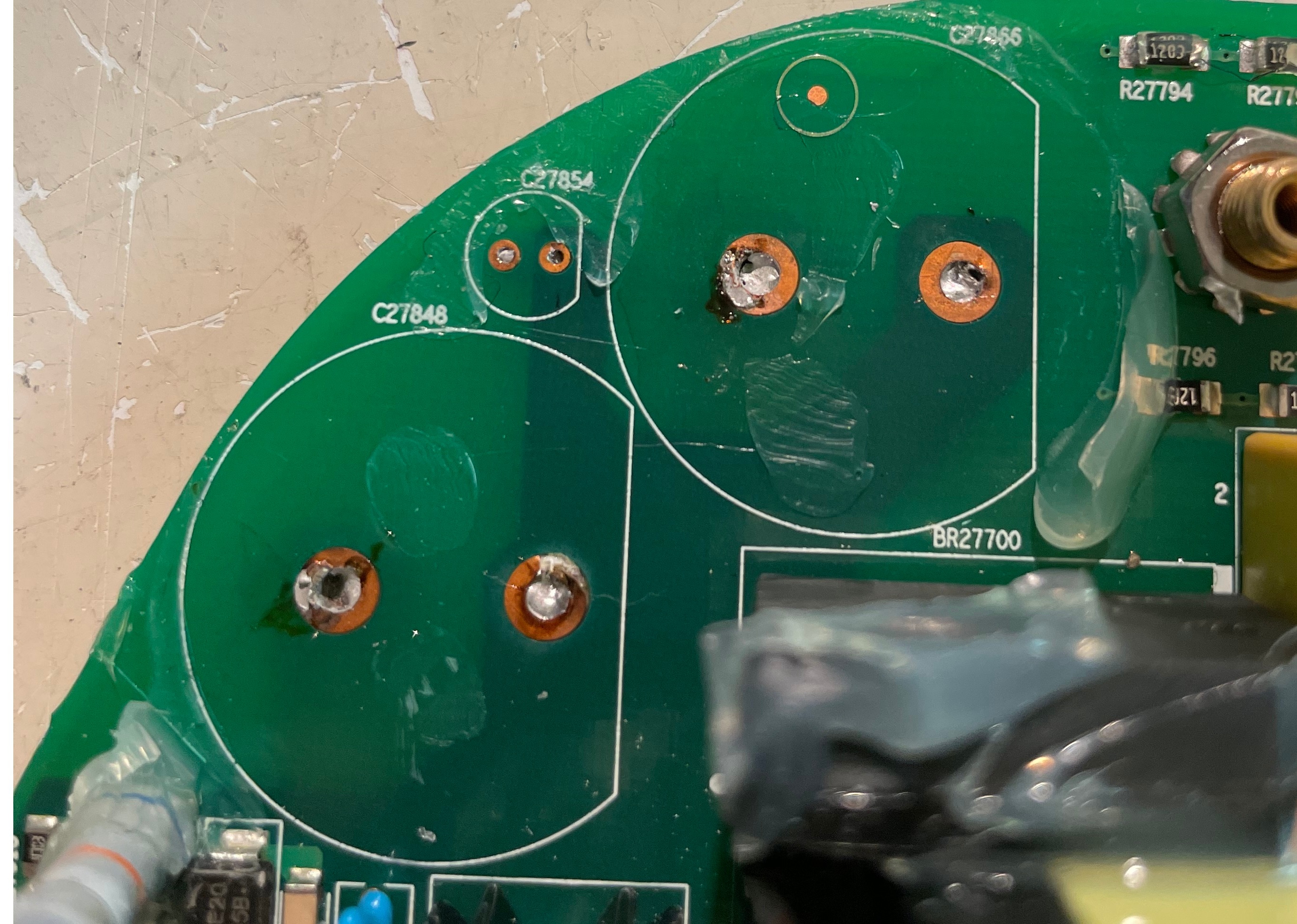
I have a dead Gen 2 Play:5. Does anyone know what the DC voltage produced after the transformer is? There are 3 3300uV capacitors there rated for 35V, so I am guessing that it is 24V, but would like confirmation before injecting 24V. If someone has a working unit, can you please measure the voltage at the points on the left of this image (where I have soldered in two black wires)?
This unit had a bad mosfet (I have removed it and the empty pads are visible in the image). I tried replacing the mosfet but didn’t have a good match. When I did this I only got about 15V but it wouldn’t generate enough amperage to allow the device to boot. When I inject 15V from an external source, it does work. That tells me that the mosfet I used wouldn’t pass enough power, or there is some other kind of problem causing the voltage sag.
Thanks!
Hi I send you private message. Voltage between those two pints when injected 24V speaker works. But power supply on its own is dead. I'm getting no volatge on the secondary side of the transformer. Why? How to figure it out if transformer is dead?
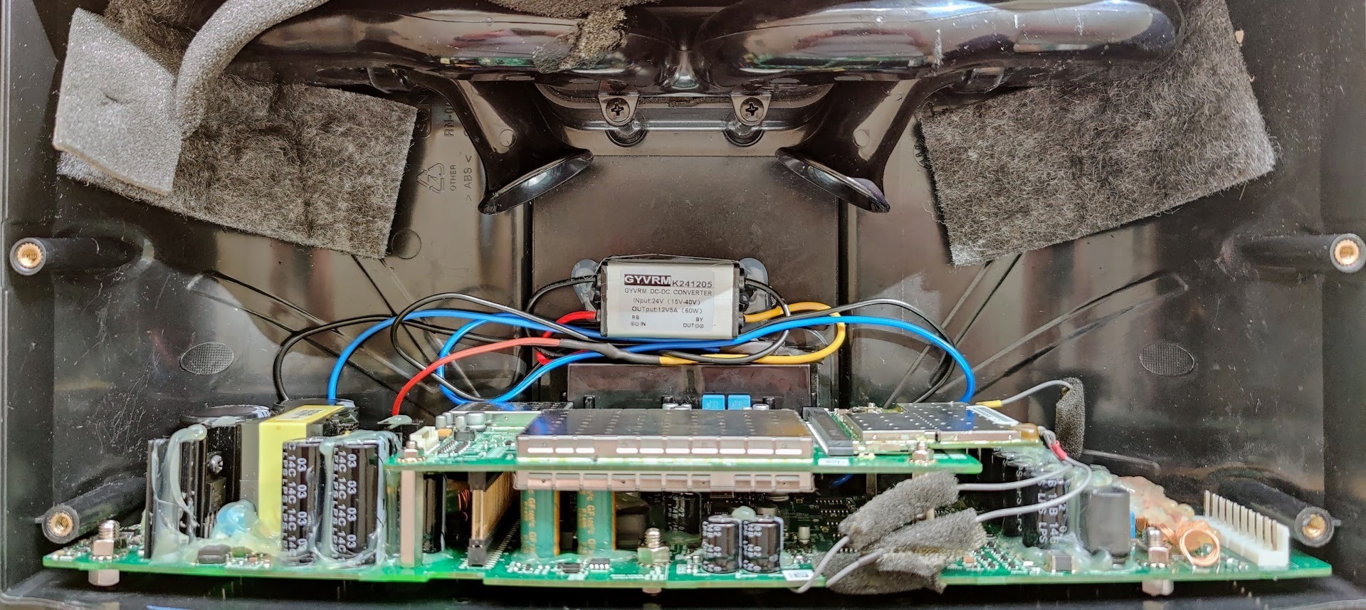
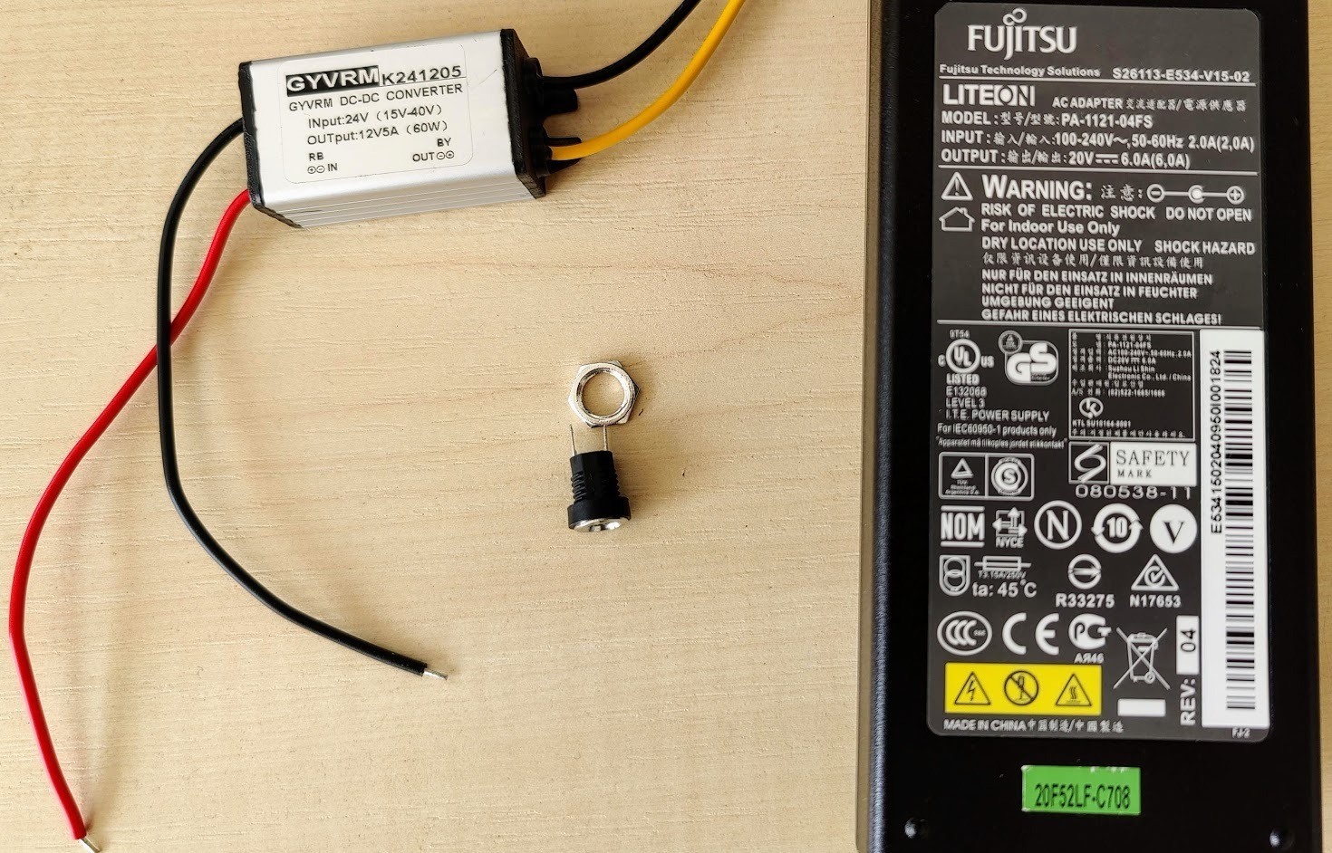
My Play:5 working again. If nothing helps you can power it with an external adapter.
My setup:
- A laptop power adapter (20V - 6A)
- DC-DC converter (24-12V)
- DC connector (female)
The power is enough for max volume and there is no problem.
Thanks for the advice.
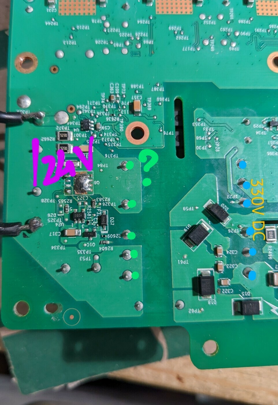
I got no voltage on green points of the transformer. 330V DC on primary side. With 24V injected speakers powers up and plays no problem. Anyone can help?
 +1
+1
Hey,
I installed a 2nf capacitor and it works again!!! And the red flashing light is gone.
Hi all
I have been making some fault analysis at my own Play:5. Unfortunately the rectifier bridge and fuse is ok. The MOSFET driver at primary side is at least not shorted.
However the driver (FET, or BJT) at the secondary side is shorted between pin1 and pin3.
However I cannot figure out the type, so it’s a little difficult. However a short circuit between legs is normally not something good ;-)
Or could I be tricked by the fact that the transformer might be connect to pin1 and pin3, so there is a DC short between pin1 and pin3 ?
I have the same issue as you: measured short on the diode on the secondary side of the transformer. Yes, I checked for the more common AC-side failure: Input fuse is short, primary rectifier diodes measure good, but DC outputs pulse. Across the secondary-side toroid output filter inductor: L27721, I see pulsing DC levels measuring from GND (pins 2/5) to the two outputs (pins 1+6 and pins 3+4). I have desoldered (and partly muscled off) D27718, which is the DC rectifying diode in one of the two DC output circuits: ST STPS20150C. Pins 1 and 3 are shorted in the PCB by design. So basically the two diodes are in parallel. That matches what I see in the reference design of the ICE2QS02, which is the AC/DC Flyback switching controller. Hidden in the glue I also found D27705, which is the rectifying diode for the other output (pins 1 and 6 of L27721). It is fine also, too much glue to see any markings, but it has ~0.48Vfwd.
Though the behavior of the circuit looks like the controller is detecting a short on the secondary,tThe resistance to GND of the two outputs is good, my DMM measures constantly increasings resistance (i.e. a mostly capacitive load, with high resistance).
The transformer connection is hard to figure out. Pin 12 of the secondary is wired directly to the bulk caps, no diode in series, which isn’t the usual way. I think the diode (D27718) is in series with the GND connection on the other end of the same winding (pin 9). C27863 and R27057 (? I scratched the silk, but it is the big resistor embedded in glue) appear to just be a snubber circuit. But the other secondary winding (pins 7 and 11) I can’t figure out what they’re doing. The only place I find a connection is to R27808 in the feedback circuit.
Based on all of that, and not finding unexpected shorts in the DC/DC section, I think the problem is still in AC/DC. The Opto measured okay, at least as 2 diodes, but I don’t know that it is transmitting. If I bother working on this again, I guess I’d use the datasheet for ICE2QS02 to see if I was getting the expected feedback signal, and look at all 7 inputs to that part.
BTW, if anyone has one of these boards working and can share what the voltages on the two outputs should be, that would help. That could be measured on C2781 and C2760 (the shorter two electrolytic caps on the AD/DC output, right next to the 2x25 header that goes up to the audio board).
I have replaced the Fuse and the rectifier and it words. Additionally i have replaced the five 820uF capacitors and two others. Now all works, but only the right middle speaker isnt working. I cant see any damages and all resistors etc working. Can you give me a notice where the damage can be?
There is no easy way to find the problem that I know of. You will see that there are 6 similar paths through the image that you posted. One of these paths likely has a problem:
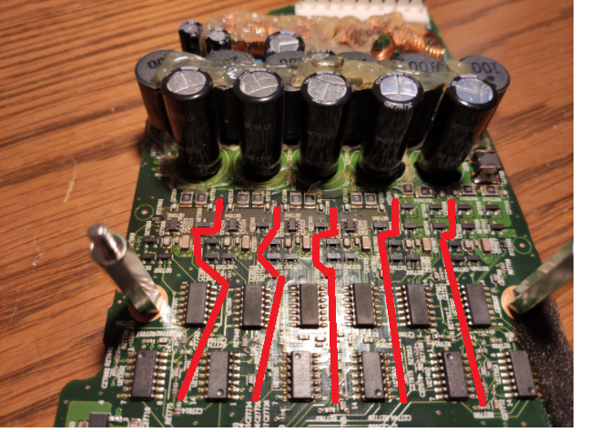
It’s been a while since I looked at this, but I think that 4 of these are for the 2 mids and 2 tweeters. For the last two (on the right by the look of it), there are two drivers for the woofer. You need to find the path that is for your bad speaker, and look at that circuit to (hopefully) find something broken. You can trace from the speaker to the white connector at the top of the image to figure out which path is broken.
I posted a long time ago an image on this board (probably this thread) where I found a broken traces which I fixed by bridging. You could have a similar problem, or it could also be a bad transistor closer to the capacitors. I think that there was a problem like this (a bad transistor) as well in this thread.
I’m trying to repair my Sonos play-5 gen-1. It has a problem that others have discussed but I’ve found no posts describing a repair. I have spoken with Sonos support and they confirmed the problem and offered a discounted replacement. I’d like to repair it. I have had good luck fixing Sonos power supply problems in the past. This play-5 seems to work. I can connect and stream music to it. The problem is that the volume is barely audible, even when set to max. There are no volume limits. There’s no distortion and both channels are working. Do any of you have suggestions on how I can further pursue this? The large caps and the rectifier measure correctly. Might this still be a power supply problem or is it more likely an amplifier issue? Any help would be appreciated.
Thanks
Lendy
Yes, you are right I was not right… Got carried away with the 220V possibility.. It must be then an overload condition somewhere since the under voltage part is fine. The excessive current detection is thru one of the vertical big resistors I believe. It sucks there is no schematic to do precise measurements, maybe it’s value changed… Hope you will find the cause of this and let us know the fix for the future.
Regards
I agree that it could be an overload problem. I removed the triple-inductor that sits between the power supply and the actual Sonos. With this out, the device still cycles power, which tells me that the problem is in the power supply rather than downstream.
So now I guess I’ll have to measure everything and compare to the working unit that I have. I did check the large resistors and all the diodes a while ago with no luck. There seems to be a lot of transistors at the front end of this supply… not sure what that’s all for given the sample schematic for the 2QSxxx doesn’t have them.
Measuring the output of the supply (on a working play:5), I see that it provides 12V and 24V supplies. That's helpful to know… If nothing else works, then I can just install an entirely new AC/DC supply - there seems to be lots of room inside the speaker. I did this with a play:1 once and it worked great.
Last resort is to add in a class D amp to it. Not ideal at all, but at least, sound is back.
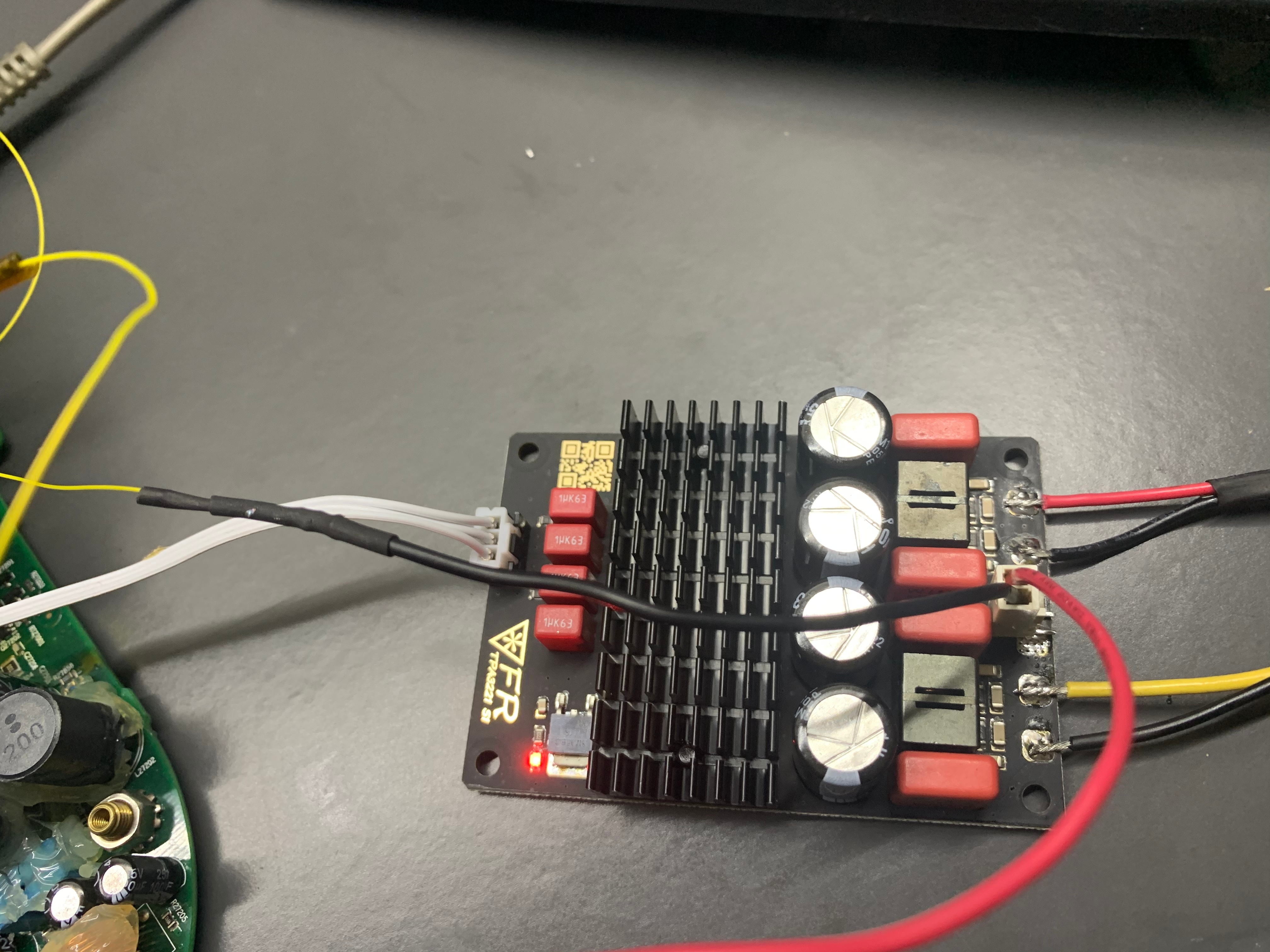
How was the sound out of that class D Amp?
If decent, what brand model, and where did you connect? It looks like directly off of the wifi/controller board?
Folks, I see some questions regarding Play 5 with low sound at max volume. I just created another post with a fix for this issue.
SO… My success 2 days ago inspired me to have another look at the two other dead units that I have.
I found a common problem to both of them, and got both working!
I had looked at everything in the high voltage section of the power supply, and couldn’t find any bad components. Despite this, the devices were both not working, and on closer inspection were resetting about once every 5 seconds… There was power ramping up, and just as it hit 20V in the driver power to the IC, it would fall back to 10V or so and start over. This is a problem that others have had on this forum (and in this thread).
I looked at the datasheet for the PWM (ICE2QS02G), and realized that I had not checked the feedback section of the circuit. This is the bit on the ‘other side’ of the opto-isolator. Most of this part of the circuit is buried in glue, but sure enough, when I checked the resistors there, both of my devices had bad resistors in the same spot! The resistor in question is a very small surface mount, with the marking “68b”. Looking in the EIA listings , this is a 4.99k resistor. Both of my devices had open resistors. I added 1/8 watt 4.7k resistors (I didn’t have 5k), and lo and behold both devices now work.
The lower value resistor did have the effect of making the device run at 13V/26V instead of 12V/24V. I don’t see this as a problem, as there are several EH31 regulators on the board, and the only thing (I think) that would be driven directly by these voltages would be the actual audio amplifiers. Those should be tolerant.
I just got mine to work with the same error, when I measured the resistor on the board it was 40-80k and when I soldered it out it was 4.9k but I replaced it with a new 5.1k and everything worked like new, I suspect a broken solder. Thanks to everyone here!
Hi all
im gunna jump on this thread and ask for some from all you fellow fixerupers
my play had a blown fuse and rectifier which i replaced. however its still dead. i have measured around the board but im not 100% what im looking for.
so the big ass caps have 86 volts across them. the ac pind of the rectifier has 90 + volts
is there any test point i should be looking for that anyone knows of?
thanks all in advance
theres also high possibility i have broke somthing replacing that rectifier. is there any test points i can test to between the rectifier and wherever.
thanks again
90V seems a bit low, what are you mains input voltage?
If you are in a 100-115V AC country you should have around 140V DC on the caps.
If you are in a 220-240V AC country, you should have around 300V DC on the caps.
Hello,
My play 5 Gen 1 is acting a bit strange. when i power the speaker up it is working fine. when i restart (unplug an replug) the play 5, to move it for example. it won’t boot up. no lights no sound.
if i wait a couple hours it will boot up again. can this be a capacitor fault or a thermistor somewhere?
I desoldered all the capacitors and measured them, they seem te be okay. (capacity measurement only, no ESR)
my voltages are similar to Anders J. Instead of 0V i get between 0-2 volts which should be 11-12 and 24V. so i think the problem should be somewhere on the HV side.
Since the speaker wont turn on for a while could this mean the capacitors have to be empty first?
(picture from Anders J.)
Hello, I believe we have similar related fail mode, the intermittent start up is related with the Vcc absence on pin 7 of the ICE2QS02 driver chip. It comes from somewhere I cannot see on the board. Since you have removed all the caps from under the glue, can you check if the small cap 100uf/25V (between the 2 big 400V caps) is connected to any of the high voltage rail? I suspect this small cap is the key to supply power to the driver IC. In my case the 2QS02 chip has no power on pin 7 and obviously it will not work.
If I power the IC externally with 12v then the power is fine. I have to figure out what is the intermittent component related to this failure.
Thanks
the small cap (C27854) is indeed connected to the high voltage rail. how can it be possible that the cap is providing the power? the other side of the cap goes to a line where some resistors (voltage dividers?) are placed
Page 6 / 9
Enter your username or e-mail address. We'll send you an e-mail with instructions to reset your password.