Hi
Play:5, manufacturing date sometime around 2009, is completely dead. No light in LED.
Found several cases of this online, but no solutions.
Does anyone have any knowledge about the problem, og better yet, schematics..
I mainly suspect problem in switch mode power supply. Have only done very basic measuring, but I find 220VAC on primary side, no power on secondary side. I think about ordering a mosfet, and/or a diode I suspect, but if I had schematics I could do some more pinpointing..

This topic has been closed for further comments. You can use the search bar to find a similar topic, or create a new one by clicking Create Topic at the top of the page.
Page 5 / 9

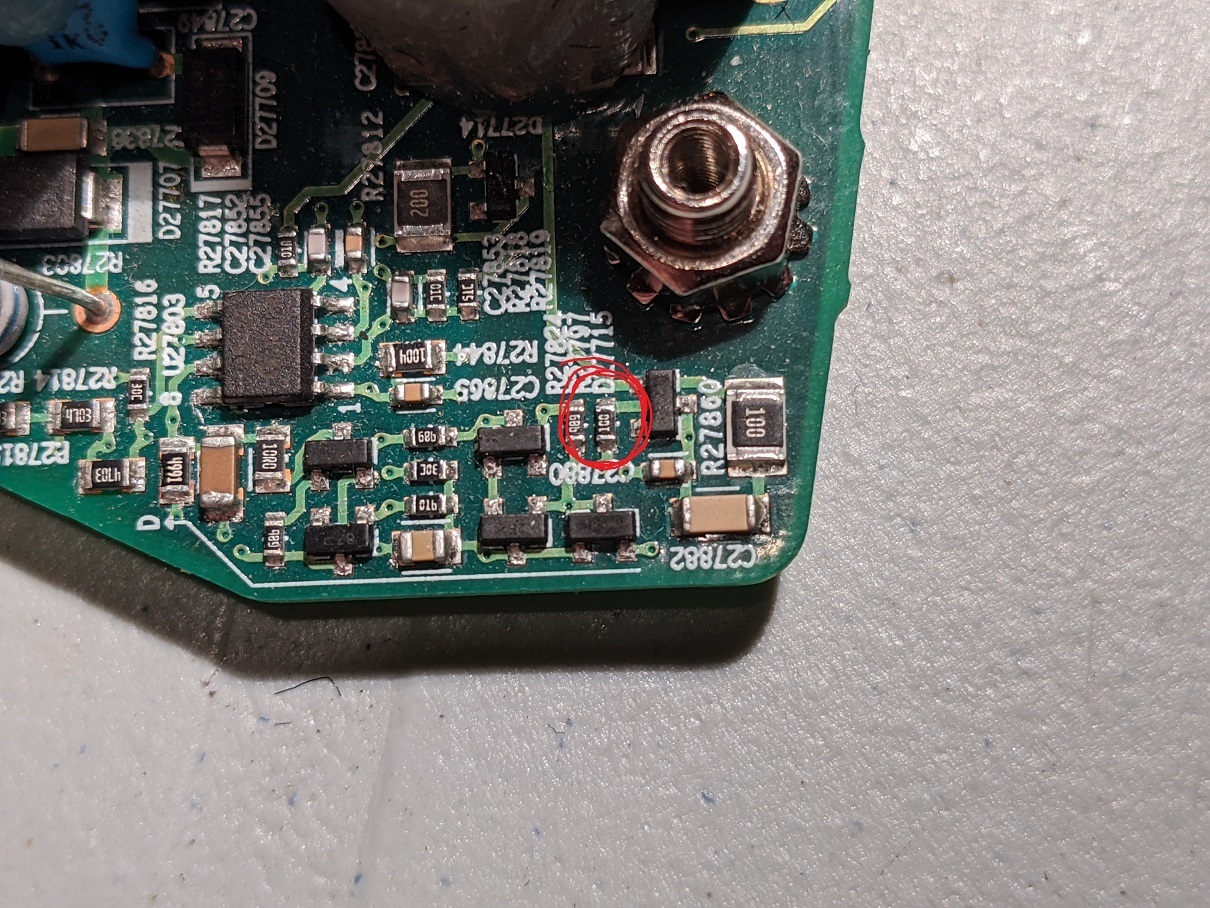
Hi guys,can someone tell me, what part it is in the red circle (capacitor, resistor) and what readings it have to?
It is the wifi card of a Player 5; Gen1.
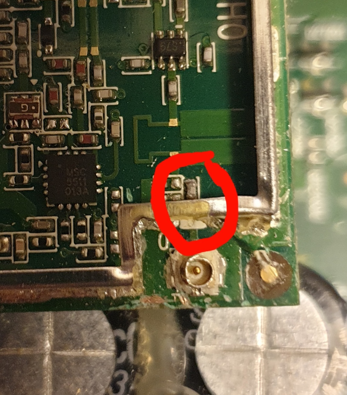
That’s a capacitor. It looks like it is in series with the antenna. I measured one(in circuit) and got readings that fluctuated a lot. They were between 0.6nF and 3nF.
For a 2.4GHz wifi, a 1nF capacitor will act like a 0.066 ohm resistance, which feels correct to me.
 +1
+1
Hi guys,can someone tell me, what part it is in the red circle (capacitor, resistor) and what readings it have to?
It is the wifi card of a Player 5; Gen1.
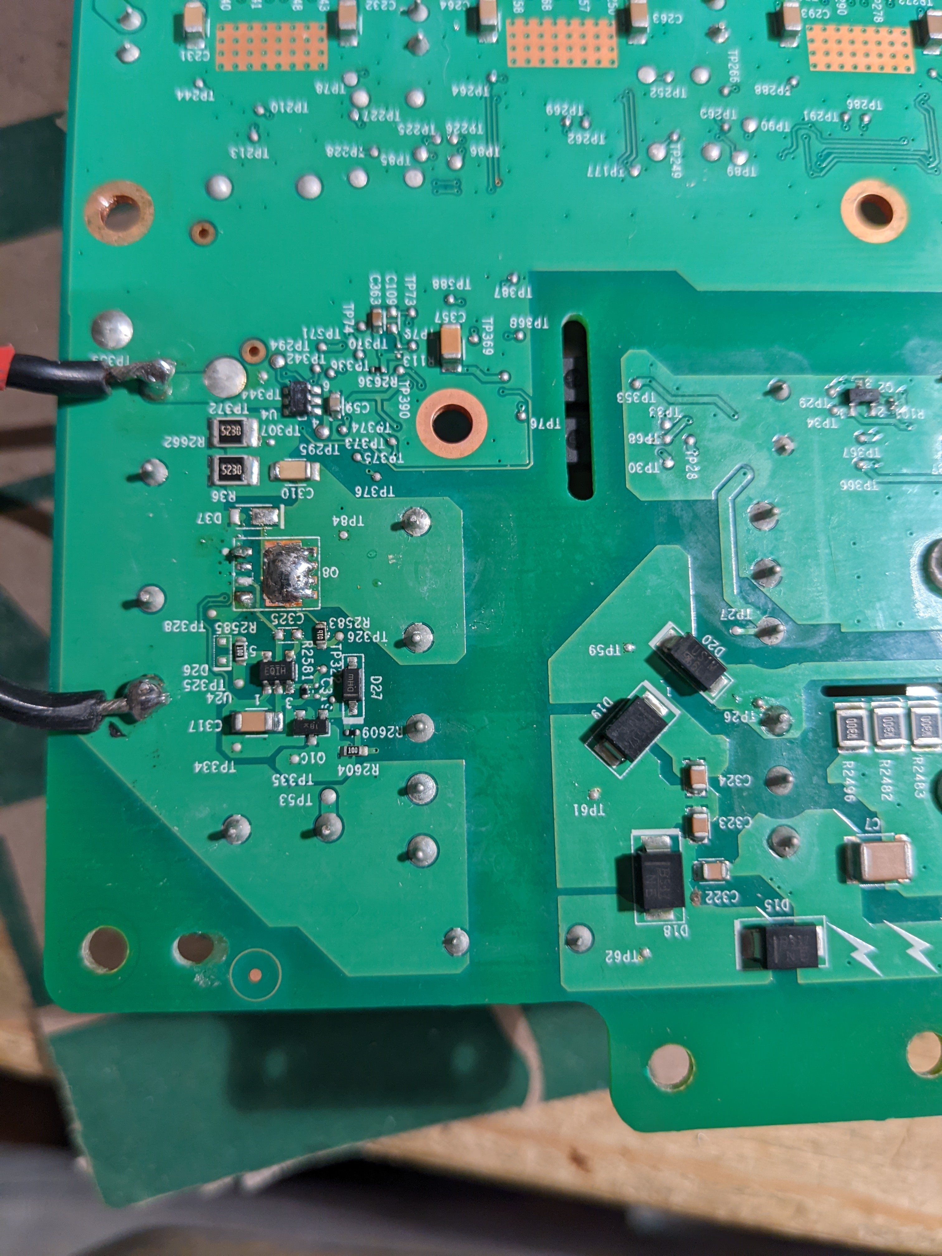
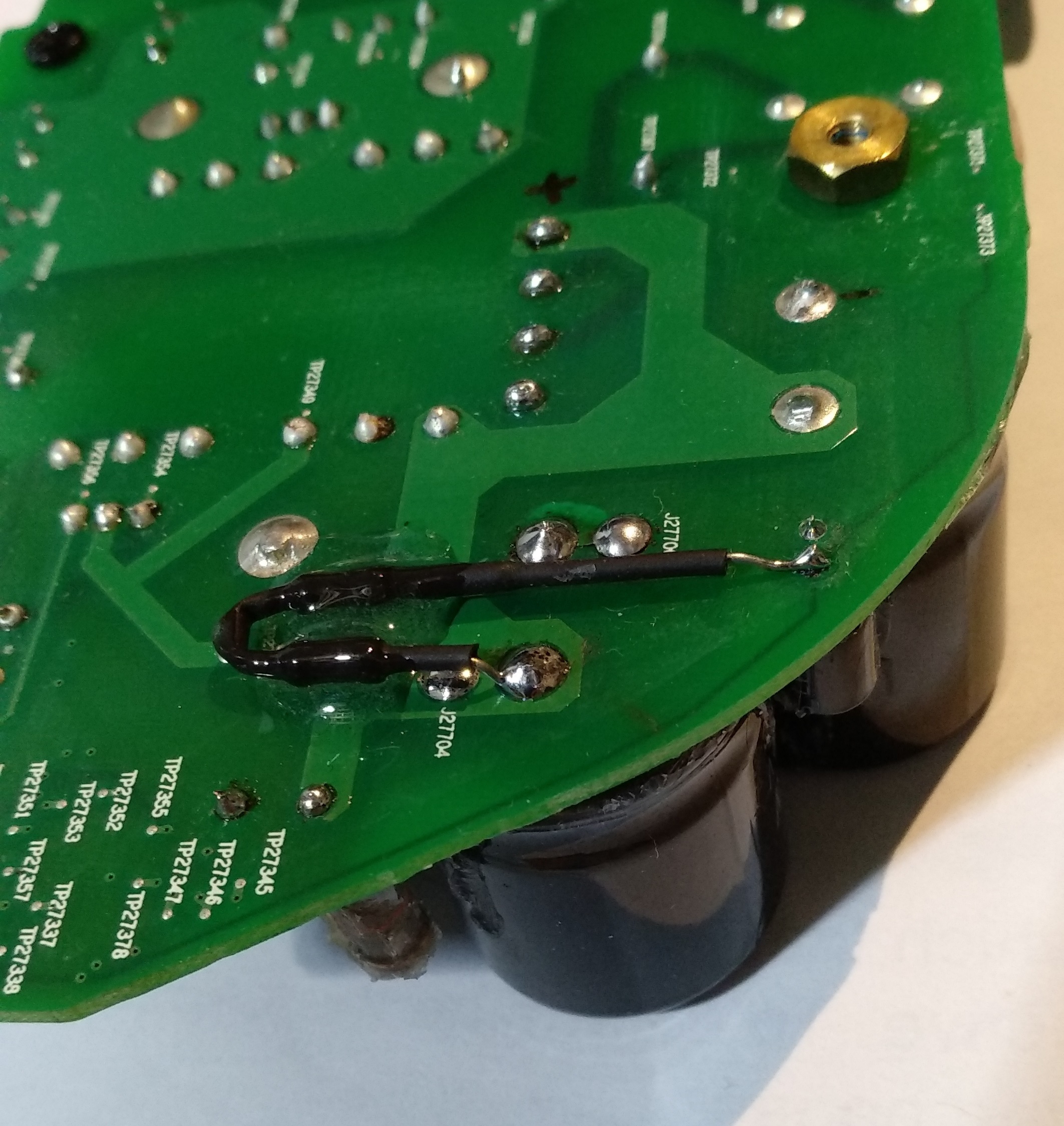
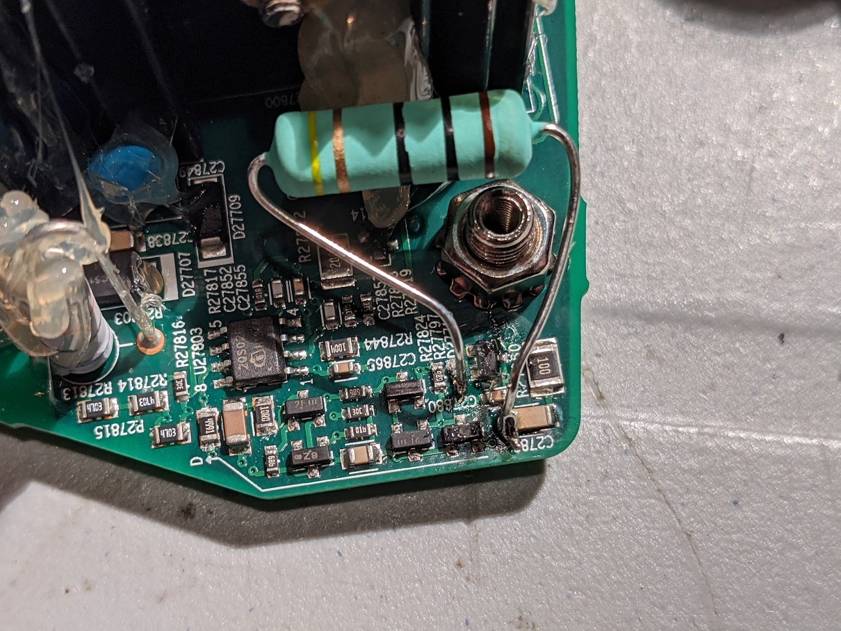
I have a dead Gen 2 Play:5. Does anyone know what the DC voltage produced after the transformer is? There are 3 3300uV capacitors there rated for 35V, so I am guessing that it is 24V, but would like confirmation before injecting 24V. If someone has a working unit, can you please measure the voltage at the points on the left of this image (where I have soldered in two black wires)?
This unit had a bad mosfet (I have removed it and the empty pads are visible in the image). I tried replacing the mosfet but didn’t have a good match. When I did this I only got about 15V but it wouldn’t generate enough amperage to allow the device to boot. When I inject 15V from an external source, it does work. That tells me that the mosfet I used wouldn’t pass enough power, or there is some other kind of problem causing the voltage sag.
Thanks!
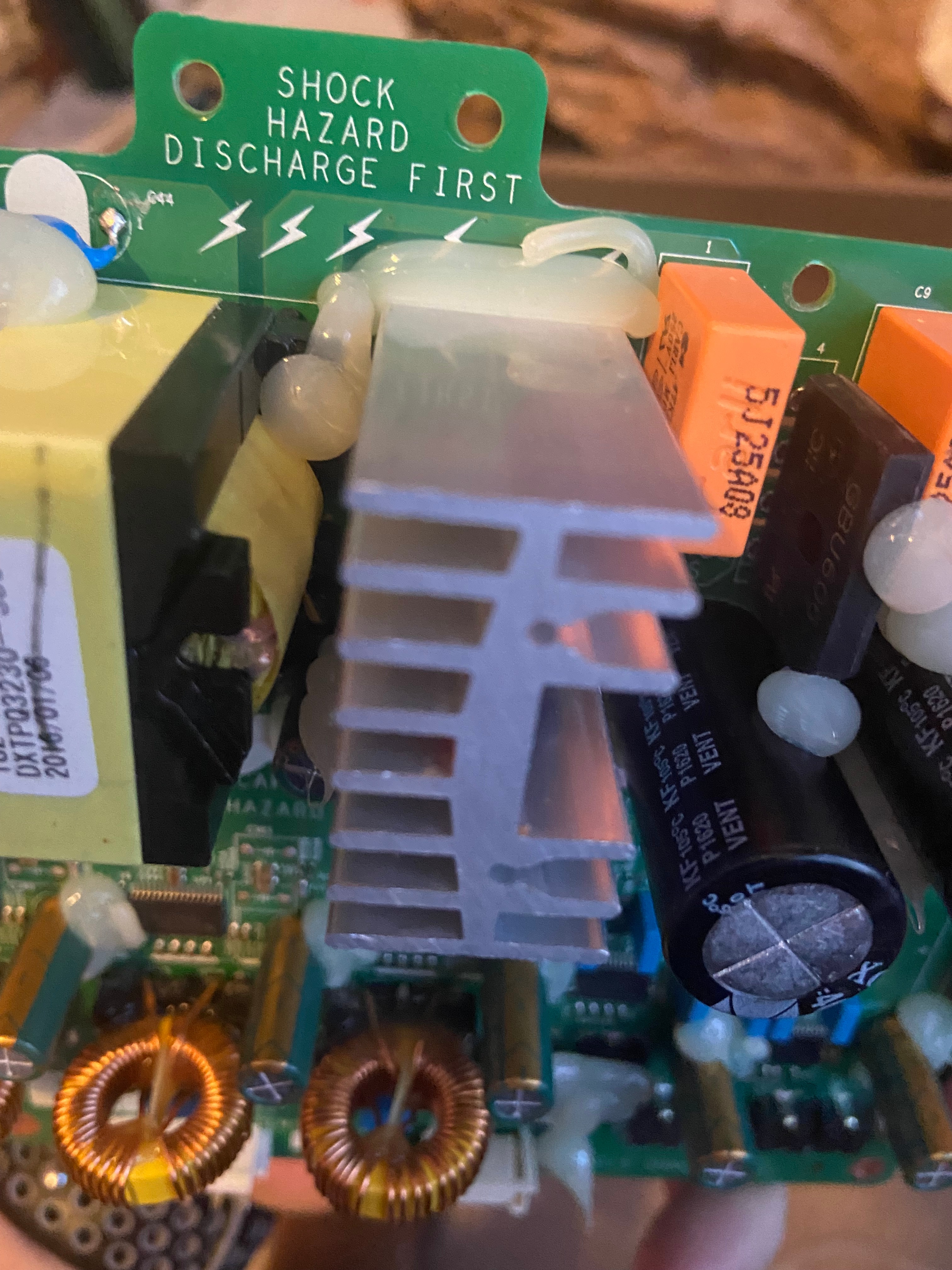
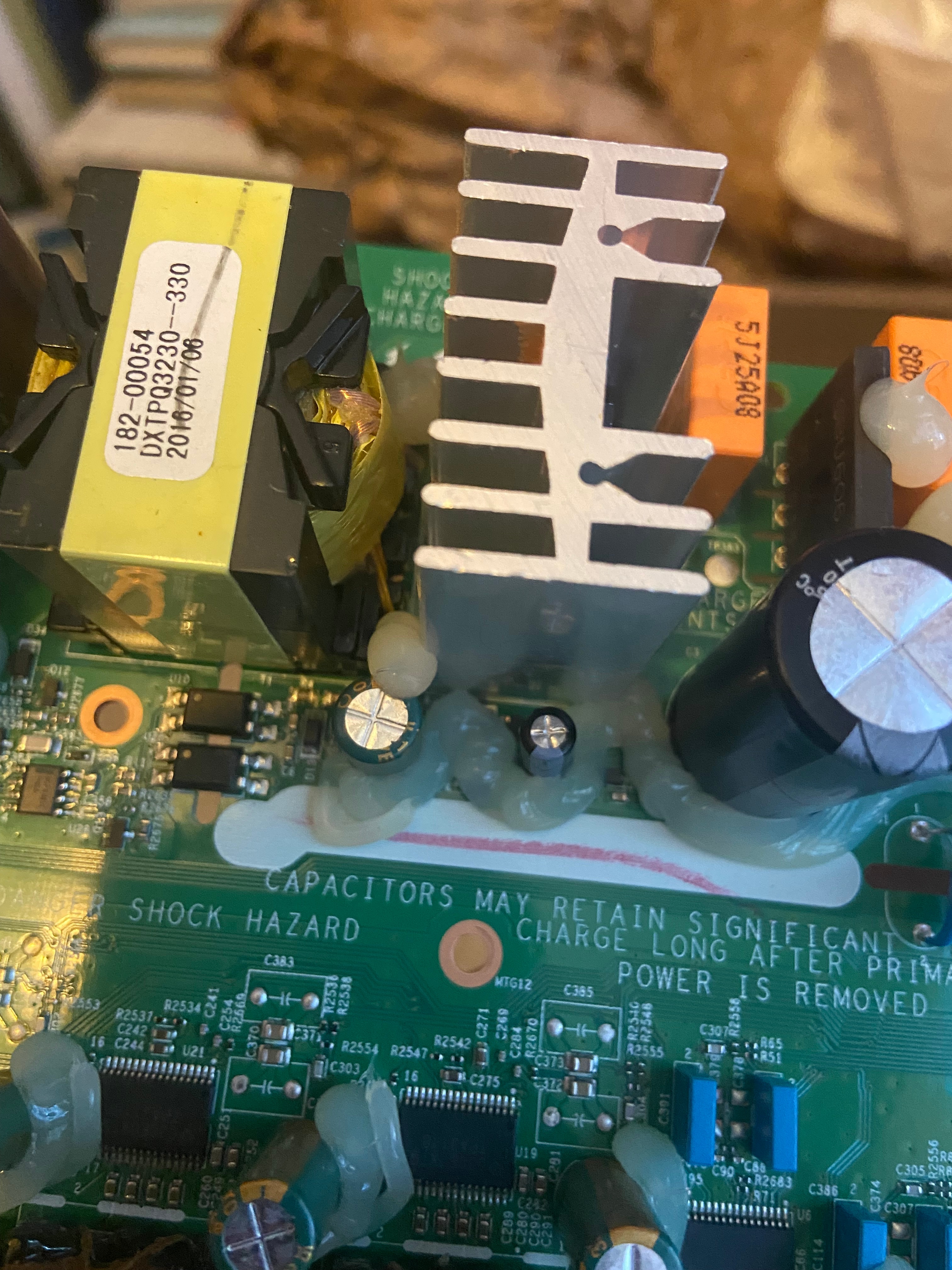
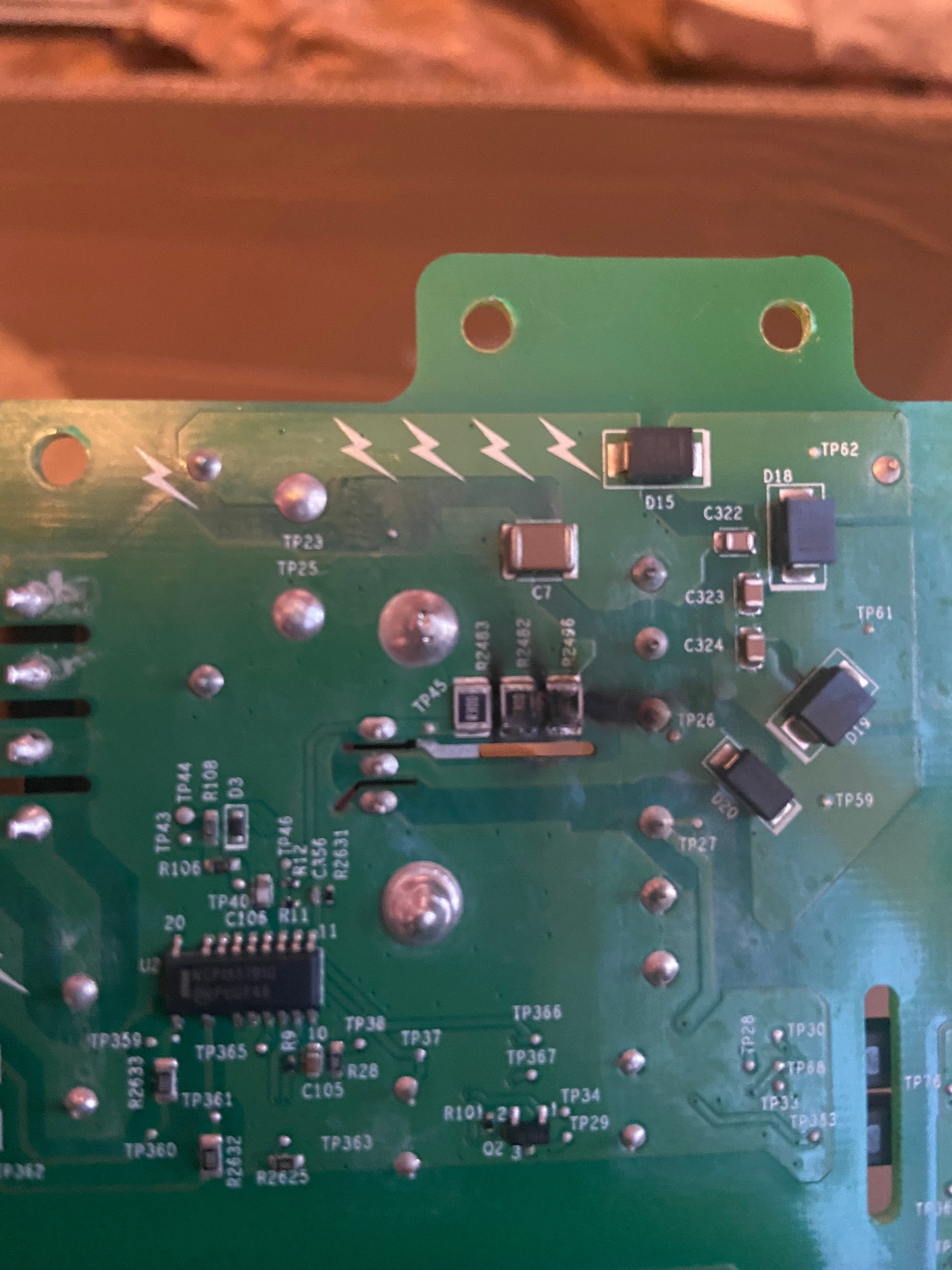
My Play 5 Gen 2 just died. It’s not the normal fuse and thermistor. Looks like it blew two resistors under the heatsink...has anyone seen this or replaced these?
I haven’t seen that before. Check that the bridge rectifier isn’t broken.
After confirming that the bridge rectifier is working, try replacing the resistors and boot it up. They could have died due to moisture or maybe some kind of transient making its way all the way into that part of the circuit. There is protection against that, but anything’s possible.
What part is the Oscillator?
My Play 5 Gen 2 just died. It’s not the normal fuse and thermistor. Looks like it blew two resistors under the heatsink...has anyone seen this or replaced these?
+1
What part is the Oscillator?
Ok I understand. So you mean that I could only use one capacitor with 2 or 3nf instead of the 2 SMD capacitors?
It’s always best to replace like for like. However, if I didn’t have the parts or was in a hurry, I would just remove the 0.1nF capacitor, install a 2nF capacitor, and see if it works. This circuitry is on the ‘high side’ of the power supply, and is just used to get the oscillator working. The circuit will be quite tolerant of capacitor variation.
You asked about voltage for the capacitor. The oscillator chip is rated for up to 27V, but it would probably be operating in the 15-20V range. I don’t know if these capacitors are between GND and VCC or not, but if you pick a capacitor that is rated ~25V or higher you will be covered.
I would make one more point … why did these 3 components get smoked? It seems like a strange part of the circuit to break in that way. It is possible that you have another problem you haven’t found yet. I would question if the oscillator itself is working or not, given it is very close to where you seem to have had a power problem.
+1
Ok I understand. So you mean that I could only use one capacitor with 2 or 3nf instead of the 2 SMD capacitors?
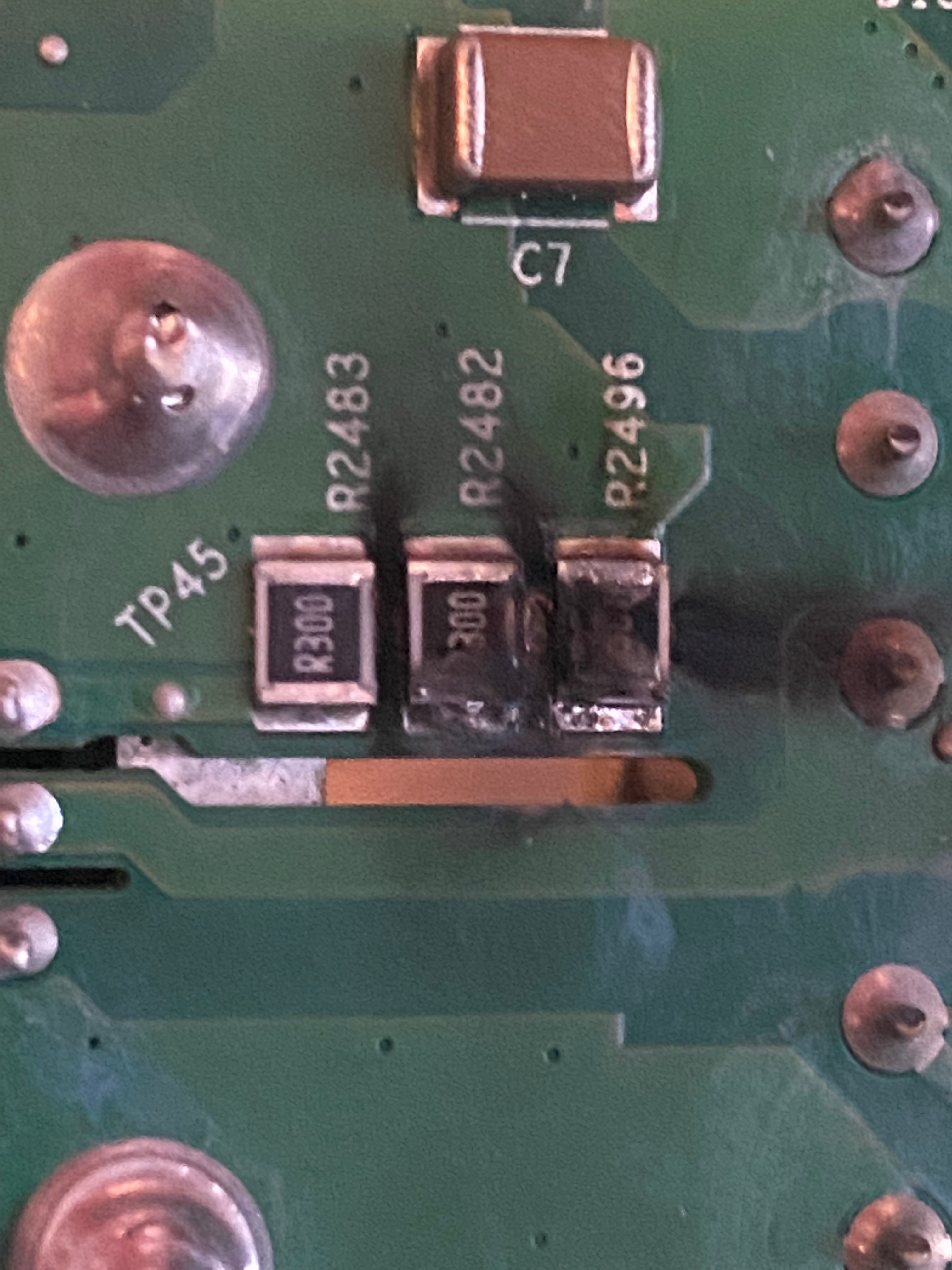
Hi guys,
can someone tell me, what parts are the following and what I need to replace?
R27817
C27852
C27855
They are burned.
100ohm
0.1nF(maybe)
2.9nF(maybe)
So what does it mean "maybe"? Can't I measure up an SMD capacitor or what?
For what it’s worth, I tried measuring these in circuit with my Fluke 87V. I got 0 for C27852, and 2.0nF for C27855. I imagine that the 0nF reading is due to the measurement being done in circuit.
Anything with this low a capacitance is going to be a filter cap, and I’m pretty sure you can just go with a low value (or maybe even no capacitor) and it would be fine. I had a look at the eval board application note, and I don’t even see these caps in that circuit diagram https://www.infineon.com/dgdl/Infineon-ApplicationNote_EvaluationBoard_80W_SMPS_QR_PWM_Controller_ICE2QS02G%20-AN-v01_00-EN.pdf?fileId=db3a30431a5c32f2011abefae1533bcd
+1
Hi guys,
can someone tell me, what parts are the following and what I need to replace?
R27817
C27852
C27855
They are burned.
100ohm
0.1nF(maybe)
2.9nF(maybe)
So what does it mean "maybe"? Can't I measure up an SMD capacitor or what?
I’ve just been repairing one of these, using many of the tips here. Some observations for those following in the footsteps of many:
I had a blown fuse, then needed to track down what else was faulty. Replaced fuse with same type. I thought the DC measurements were suggesting a problem with the MOSFET switch, so I changed that out with another N-Channel of similar value I had on hand. The Dim Bulb Tester indicated there was still something wrong, but interestingly I was getting some useful DC voltages. My DC measurements of the bridge rectifier didn’t suggest it was faulty, so I pressed on. Decided to try plugging directly in to the mains. Big mistake. Loud explosion as the fuse self-destructed.
So stepping back I decided to use a process of elimination. I removed both 100uF charge capacitors. Replaced fuse, connected Dim Bulb Tester, still showed excess current. I then removed the bride rectifier and replaced with another I had on hand. Success: no more large current drain.
I intend changing out the 100UF caps with high quality brand, as well as the electro caps on the cold side.
But this failure of the bridge rectifier is a weird one. I fix Switched Mode Power Supplies a fair bit. Bridge rectifiers either go short or open circuit. It’s as if this is failing under mains voltage?
Anyway, that bridge rectifier is a bugger to get out. Removing the two 100uF caps gave better access to be able leverage it out whilst hitting it with the soldering iron (after having previously used a desoldering gun on those terminals).
+1
And can someone tell me, what size of smd resistors they are, I can't measure up this size
+1
Hi guys,
can someone tell me, what parts are the following and what I need to replace?
R27817
C27852
C27855
They are burned.
100ohm
0.1nF(maybe)
2.9nF(maybe)
Does it matter, how mich V the capacitor must have? And maybe means, i cannot measur up an SMD capacitor ?
Hello, thanks for the picture.
I have-it fixed finally but I do not know the cause. Here it is in words and pictures:
First, small cap (C27854) is not charging from the AC side, those are probably discharge resistors to the remaining capacity in the filtering caps. It’s another mechanism I could not figure out. The C27854 is providing power to the ICE2QS02 driver chip. It goes thru all those small diodes and caps on the edge of the board. The normal behavior on the voltage for C27854 is that is charging up to around 20V slowly and then ( some of those diodes and transistors do that) turns on the power on the ICE2QS02.
Once the chip is starting the voltage is self sustaining to around 13 V, I do not understand from where, maybe from the fly back transformer winding itself.
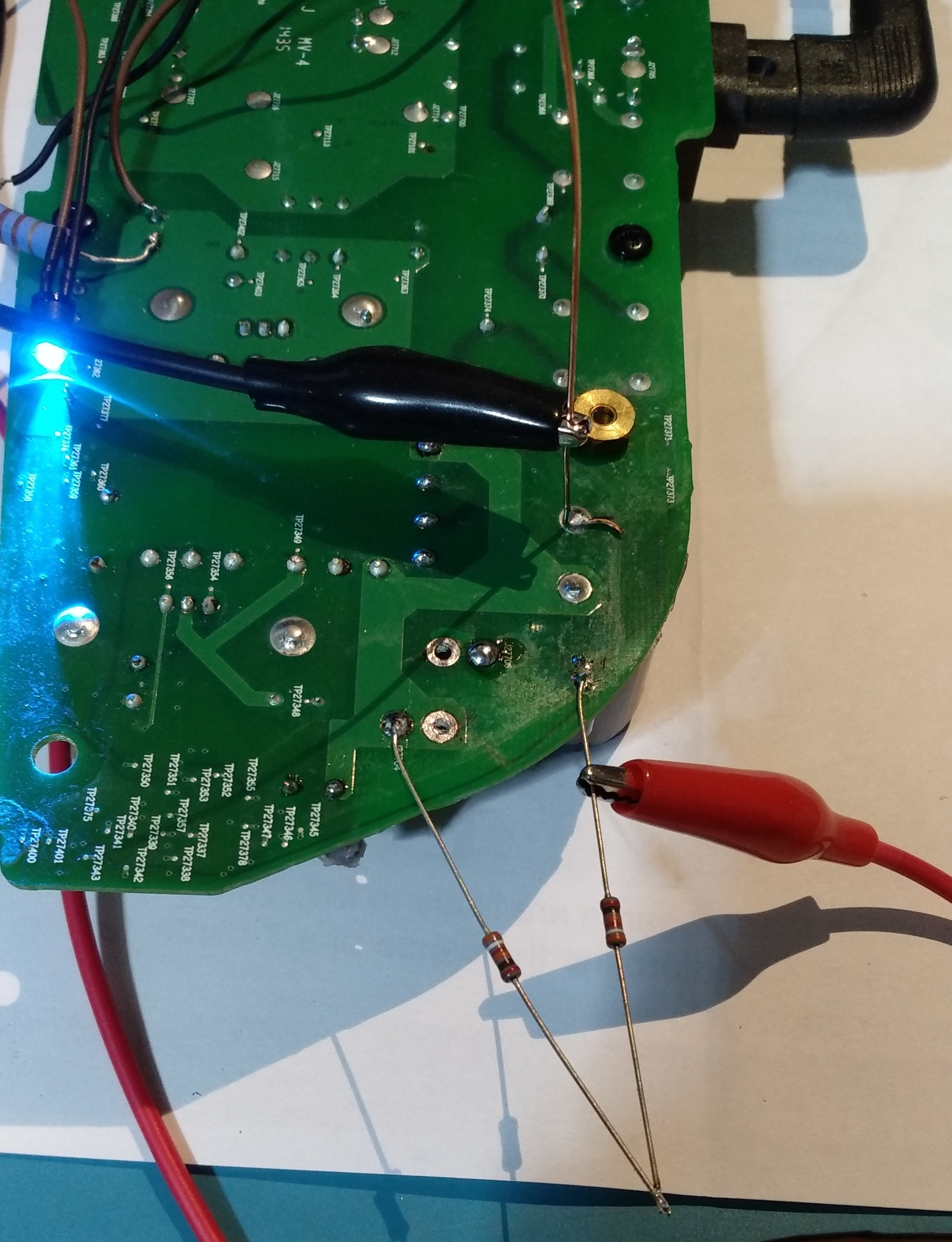
So for me the challenge was to produce the charging of the C27854 up to 20 to start up the IC. I did this by putting 2 390Kohm from the + on the big caps. I monitor the voltage and it’s ramping up slow, like a second or two. After it reaches 20V the IC starts and it self sustain to 13V. It’s 3 days already and still works! meaning there is no other fail. There was no problem in the fuse or rectifier, nothing burned. As you can see the LED turns on with the 2 resistors soldered. This is the story of this fix.
I have no power on pin 7 on ICE2QS02 and when i measure on C27854 it goes from 9 to 18 VDC in a 2-3 second loop, is this the same behaviour as you had?
a normal board ,the C27854 is 15VDC, the pin 7 on ice2qs02 is 1.5 VDC
Hello, thanks for the picture.
I have-it fixed finally but I do not know the cause. Here it is in words and pictures:
First, small cap (C27854) is not charging from the AC side, those are probably discharge resistors to the remaining capacity in the filtering caps. It’s another mechanism I could not figure out. The C27854 is providing power to the ICE2QS02 driver chip. It goes thru all those small diodes and caps on the edge of the board. The normal behavior on the voltage for C27854 is that is charging up to around 20V slowly and then ( some of those diodes and transistors do that) turns on the power on the ICE2QS02.
Once the chip is starting the voltage is self sustaining to around 13 V, I do not understand from where, maybe from the fly back transformer winding itself.
So for me the challenge was to produce the charging of the C27854 up to 20 to start up the IC. I did this by putting 2 390Kohm from the + on the big caps. I monitor the voltage and it’s ramping up slow, like a second or two. After it reaches 20V the IC starts and it self sustain to 13V. It’s 3 days already and still works! meaning there is no other fail. There was no problem in the fuse or rectifier, nothing burned. As you can see the LED turns on with the 2 resistors soldered. This is the story of this fix.
I have no power on pin 7 on ICE2QS02 and when i measure on C27854 it goes from 9 to 18 VDC in a 2-3 second loop, is this the same behaviour as you had?
i have the same problem, pin7 no power(0.1 or 0.5v), c27854 get loop vdc,have you fixed the problem by use putting 2 390Kohm from the + on the big caps?
How mich W must have the resistor or doesnt care?
maybe 0.1w or below,i guess
+1
How mich W must have the resistor or doesnt care?
Hi guys,
can someone tell me, what parts are the following and what I need to replace?
R27817
C27852
C27855
They are burned.
100ohm
0.1nF(maybe)
2.9nF(maybe)
+1
Hi guys,
can someone tell me, what parts are the following and what I need to replace?
R27817
C27852
C27855
They are burned.
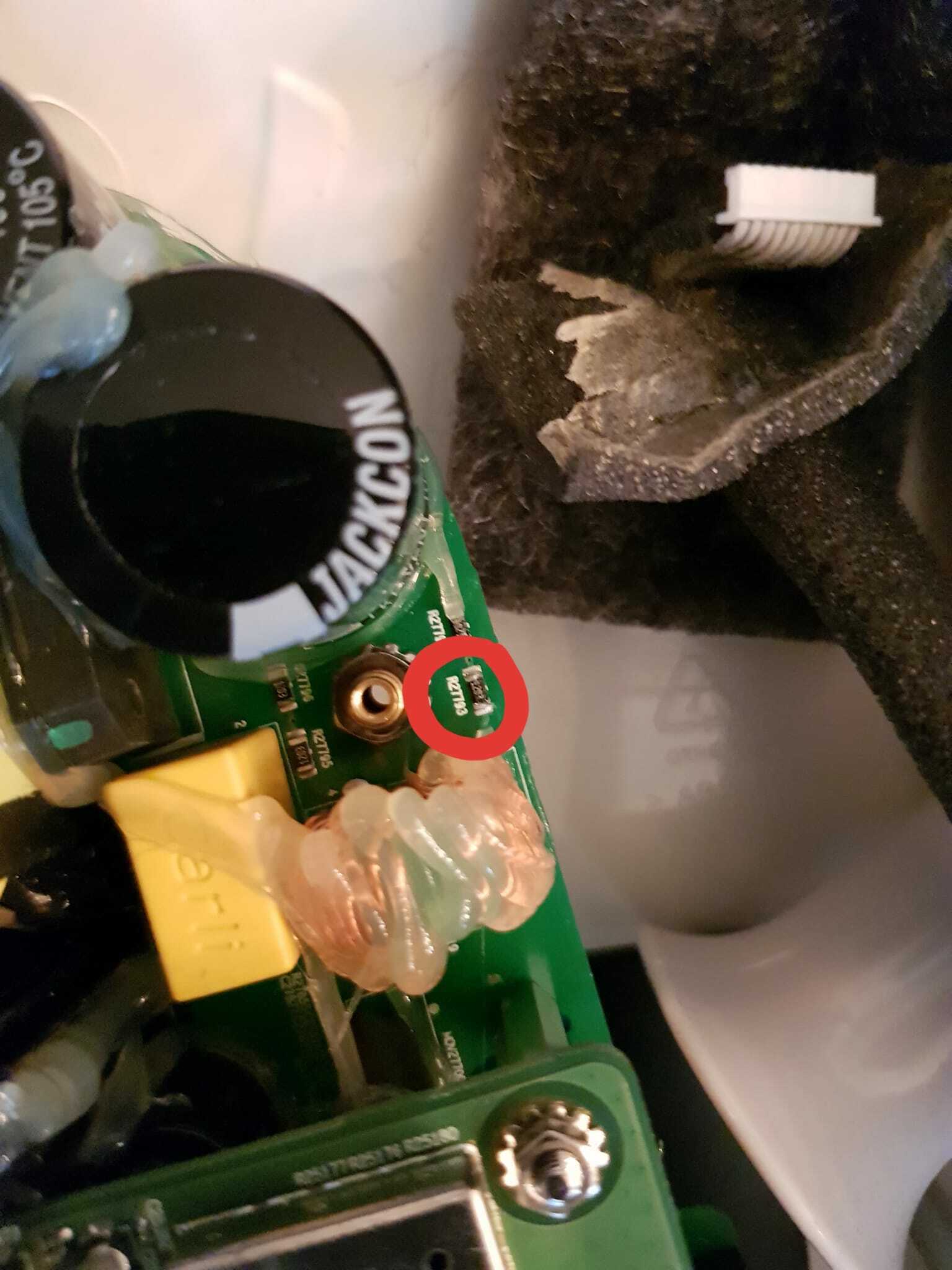
I just had a success fixing a dead play:5 so thought I’d share it. The device would not boot up. When I measured the voltage driving the PWM chip, I found it was ramping slowly from 7-8V up to about 19V, then dropping back to 7-8V and repeating. The frequency of this was about 3-4 seconds.
I found a 10 ohm resistor that was open (R27797). I replaced it with another 10 ohm and the device now works. I only had a much much larger wattage resistor, but it got the job done. Images are attached.
I had some other dead boards with the exact same ramping of voltage. Unfortunately when I checked them, none of them had the same failure. Hopefully this can help someone else though!
Thanks Tim,
Replacing this resistor and a 120k resistor near the ac filters fixed my dead play 5.
Tom
Hi,
Thought I would add some information to this thread since it helped me resurrect a dead play 5 gen 1.
A few months ago my father informed me that one of his two play 5 speakers was completely dead. After browsing the internet we found that the fuse and rectifier could be possible causes. We opened the speaker and found that fuse was still intact. Some more browsing led us to this thread with other possible causes for a dead speaker. None of the earlier mentioned resistors etc. seemed to be the issue in our unit. Then after randomly measuring resistors with a multimeter I found R27793 near one of the big capacitors being open. 1203 is printed on the resistor and according to this page that means 120 kΩ.
A new 120 kΩ resistor was then soldered to the board and now the speaker is working again. ![]()
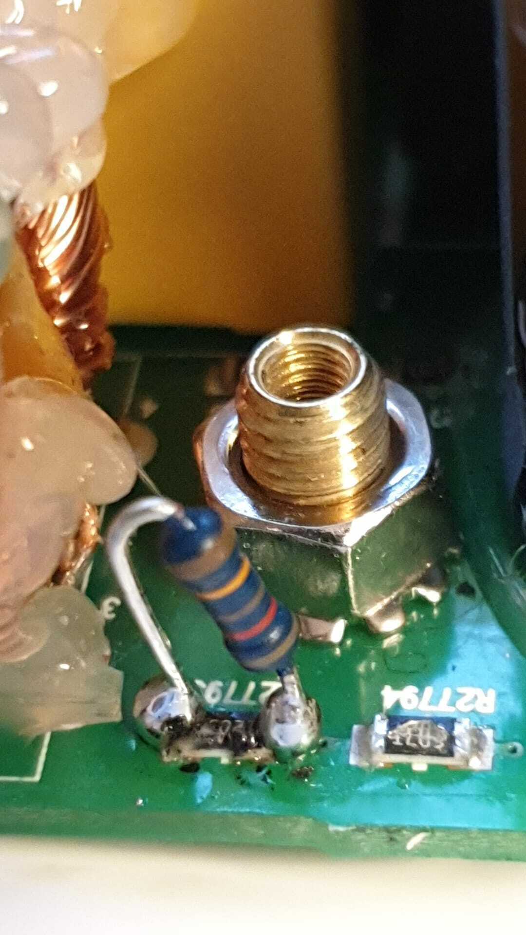
Hopefully this can be of some help if someone else would have the same issue. ![]()
It's just a damn psu.
Strange that none of you 'tronics boffins have risen to the challenge of reverse engineering the Play 5 psu schematics.
A hand-drawn scribbled diagram, that ain't gonna offend our masters. SONOS might even
appreciate the good-will benefit of allowing it in these pages. Otherwise we're all still buzzing around like flies circling meat in plastic film, cursing their product brand telling others to avoid it.
Short-circuit Player 5
Dead Player 5. Blown fuse. Installed larger fuse - tripped kitchen power supply. Tested 8ohms across mains input. De-soldered/pulled one leg of the 2nd right-hand green filter coil (facing mains plug). Short cct now moved to bridge-rectifier. Meaning: replace the blown fuse (small brown cylinder behind power input socket) but don’t waste time checking onward components to rectifier. It’s the 4-pin big black rectangular bastard behind first fat capacitor to the right of power input socket.
Do not be dissuaded, have patients. Detach hot-glue from components with drips of Isopropyl Alcohol bit-by-bit with screwdriver, easy-peasy. Firstly remove fat capacitor (notice white -ve polarity position). Second: the 4 rectifier legs. High class Sonos pcb (board) needs high temp narrow soldering iron bit.
Use de-soldering braid and solder flux if you have it. Medium screwdriver leverage of component against board.
Yes, ESR tested both fat caps OK. Others too. Gonna replace bridge rectifier and fat caps. Awaiting delivery and, your Comments / advice.
Great, i will try to measure the voltage and see if the result could guide me.
Short circuit Player 5.
Dr Phil, your latest Post. Sorry I can’t find a “New Post” button on this page. Have to ride on yours.
Dead Player 5. Blown fuse. Installed larger fuse - tripped kitchen supply. Tested 8ohms across mains input. De-soldered/pulled one leg of the 2nd right-hand green filter coil (facing mains plug). Short cct now moved to bridge-rectifier. Meaning: replace the blown fuse but don’t waste time checking onward components to rectifier. It’s the 4-pin big black rectangular bastard behind the fat capacitor to the right.
Do not be dissuaded, have patients. Detach hot-glued components with drips of Isopropyl Alcohol bit by bit with screwdriver, easy-peasy. Firstly remove fat capacitor (notice white -ve polarity position). Second: the 4 rectifier legs. High class Sonos pcb (board) needs high temp narrow soldering iron bit. De-soldering braid and solder flux if you have it. Medium screwdriver leverage of component against board.
Yes, ESR tested both fat caps OK. Others too. Gonna replace bridge rectifier and fat caps. Awaiting delivery. And Comments / advice.
Page 5 / 9
Enter your username or e-mail address. We'll send you an e-mail with instructions to reset your password.