Hi
Play:5, manufacturing date sometime around 2009, is completely dead. No light in LED.
Found several cases of this online, but no solutions.
Does anyone have any knowledge about the problem, og better yet, schematics..
I mainly suspect problem in switch mode power supply. Have only done very basic measuring, but I find 220VAC on primary side, no power on secondary side. I think about ordering a mosfet, and/or a diode I suspect, but if I had schematics I could do some more pinpointing..

This topic has been closed for further comments. You can use the search bar to find a similar topic, or create a new one by clicking Create Topic at the top of the page.
Page 6 / 9
Great, i will try to measure the voltage and see if the result could guide me.

Hi Dr_Phil.
Yes, if that resistor isn’t reading 4.5k, it will definitely affect the voltages. I would say though, it is rare in my experience for a failure like that. Resistors usually short out entirely, or blow open. Landing somewhere in the middle (like 12k) is unusual. It could be that the chip is actually ‘open’, but you are getting some other resistance measurement from the circuit itself.
I lost my info where I reverse engineered that part of the circuit, but the usual way that it works is that there is a reference voltage, and a feedback loop. A simple voltage divider is made on the output voltages, and that voltage is compared to the reference voltage. Often it is something like Vout=Vref*(1+V1/V2). Vref would depend on a chosen reference voltage elsewhere on the board, and the circuit designer chooses V1 and V2 to get the desired output. SO… If you are getting 12k instead of 4.5V, then your circuit is probably generating something like 5v/10v, instead of the required 12v/24v.
If you have a voltmeter, you can check what’s happening to the output voltages. Also, you would ideally test that bad chip after removing it from the circuit, but these are so small that it may be impossible to remove it without damaging it.
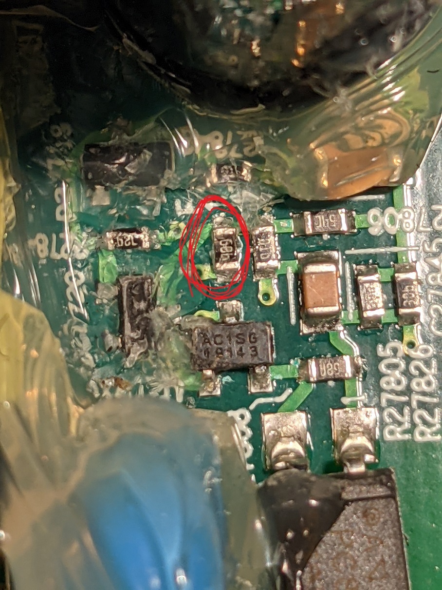
I have two broken Play:5 units and when i check the “68b” resistor on them one reads 4.5 kOhm and the other one reads 12 kOhm, could the one that reads 12 kOhm create the problem you describe
SO… My success 2 days ago inspired me to have another look at the two other dead units that I have.
I found a common problem to both of them, and got both working!
I had looked at everything in the high voltage section of the power supply, and couldn’t find any bad components. Despite this, the devices were both not working, and on closer inspection were resetting about once every 5 seconds… There was power ramping up, and just as it hit 20V in the driver power to the IC, it would fall back to 10V or so and start over. This is a problem that others have had on this forum (and in this thread).
I looked at the datasheet for the PWM (ICE2QS02G), and realized that I had not checked the feedback section of the circuit. This is the bit on the ‘other side’ of the opto-isolator. Most of this part of the circuit is buried in glue, but sure enough, when I checked the resistors there, both of my devices had bad resistors in the same spot! The resistor in question is a very small surface mount, with the marking “68b”. Looking in the EIA listings , this is a 4.99k resistor. Both of my devices had open resistors. I added 1/8 watt 4.7k resistors (I didn’t have 5k), and lo and behold both devices now work.
The lower value resistor did have the effect of making the device run at 13V/26V instead of 12V/24V. I don’t see this as a problem, as there are several EH31 regulators on the board, and the only thing (I think) that would be driven directly by these voltages would be the actual audio amplifiers. Those should be tolerant.
I just had a success fixing a dead play:5 so thought I’d share it. The device would not boot up. When I measured the voltage driving the PWM chip, I found it was ramping slowly from 7-8V up to about 19V, then dropping back to 7-8V and repeating. The frequency of this was about 3-4 seconds.
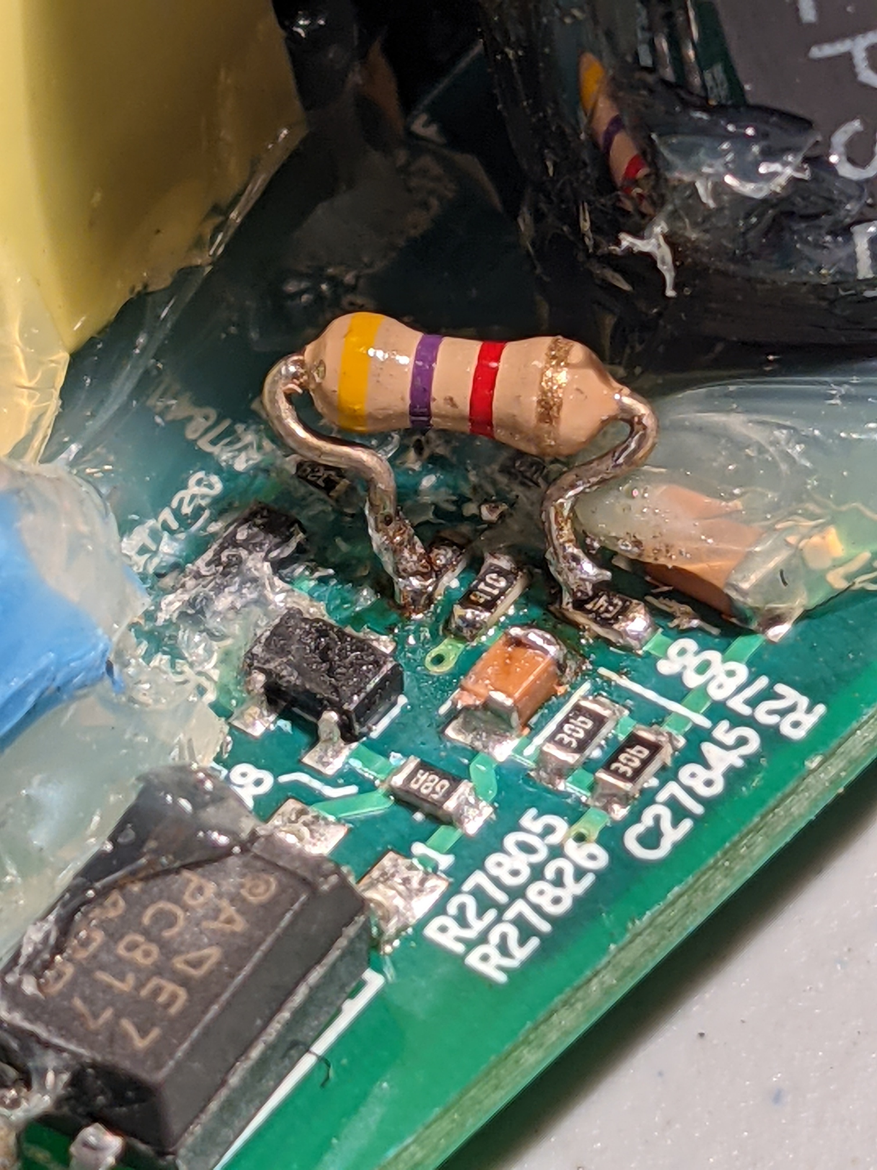
I found a 10 ohm resistor that was open (R27797). I replaced it with another 10 ohm and the device now works. I only had a much much larger wattage resistor, but it got the job done. Images are attached.
I had some other dead boards with the exact same ramping of voltage. Unfortunately when I checked them, none of them had the same failure. Hopefully this can help someone else though!

Thanks Tim. I have not order the parts yet. 😀 will place an order for both 34N and DMB. Cheers!!
Hi,
I have a new problem with my play 5.
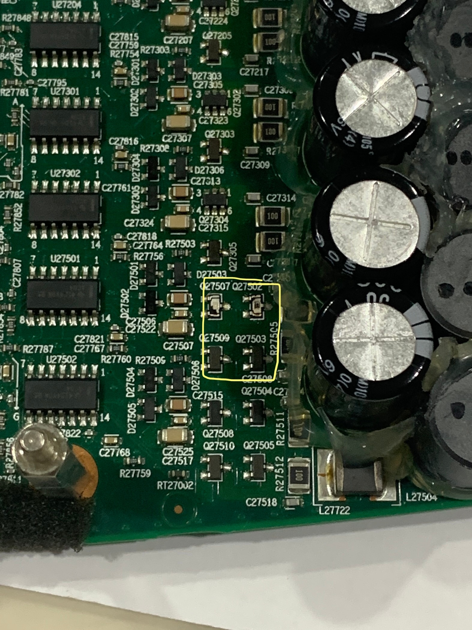
2 components were blown Q27507/Q27502.
2 components shorted, Q27509/27503.
I think the part numbers are 34N B1. What are these? Mosfet? Appreciate it if anyone can share the part numbers of that 4 components in yellow box. Thks!
On my board, all 4 of those components are the same, and are labelled DMB B8. That is a DMP3098L (P-CHANNEL ENHANCEMENT MODE MOSFET https://www.alldatasheet.com/datasheet-pdf/pdf/405103/DIODES/DMP3098L.html?)
The really weird part though is that “34N” is a different device! That’s an N-channel mosfet: https://www.diodes.com/assets/Datasheets/ds31787.pdf
Good luck!
Thanks Tim. You are truly helpful. Looking thru the datasheet, the Q27509/Q27503 on my board is indeed 34N B1, same marking placement as well. I am guessing those 2 blown would be the same.
Looking at my board again, only Q27515/Q27504 are labeled as DMB AN.
The rest like Q27203/Q27205/Q27303/Q27205 are all 34N B1
Fingers cross, thanks.
I opened up another PLay:5.
The two on the right are 34n, and the two on the left are DMB. When I read the first board, I had confirmation bias as I was expecting to see DMB, and I was looking through a bunch of glue residue. Those are indeed 34N as well.
This actually makes a lot of sense -- there should be both N and P channel to drive the speaker.
Sorry I misled you. I hope you see this before ordering parts!
Hi,
I have a new problem with my play 5.
2 components were blown Q27507/Q27502.
2 components shorted, Q27509/27503.
I think the part numbers are 34N B1. What are these? Mosfet? Appreciate it if anyone can share the part numbers of that 4 components in yellow box. Thks!
On my board, all 4 of those components are the same, and are labelled DMB B8. That is a DMP3098L (P-CHANNEL ENHANCEMENT MODE MOSFET https://www.alldatasheet.com/datasheet-pdf/pdf/405103/DIODES/DMP3098L.html?)
The really weird part though is that “34N” is a different device! That’s an N-channel mosfet: https://www.diodes.com/assets/Datasheets/ds31787.pdf
Good luck!
Thanks Tim. You are truly helpful. Looking thru the datasheet, the Q27509/Q27503 on my board is indeed 34N B1, same marking placement as well. I am guessing those 2 blown would be the same.
Looking at my board again, only Q27515/Q27504 are labeled as DMB AN.
The rest like Q27203/Q27205/Q27303/Q27205 are all 34N B1
Fingers cross, thanks.
Hi,
I have a new problem with my play 5.
2 components were blown Q27507/Q27502.
2 components shorted, Q27509/27503.
I think the part numbers are 34N B1. What are these? Mosfet? Appreciate it if anyone can share the part numbers of that 4 components in yellow box. Thks!
On my board, all 4 of those components are the same, and are labelled DMB B8. That is a DMP3098L (P-CHANNEL ENHANCEMENT MODE MOSFET https://www.alldatasheet.com/datasheet-pdf/pdf/405103/DIODES/DMP3098L.html?)
The really weird part though is that “34N” is a different device! That’s an N-channel mosfet: https://www.diodes.com/assets/Datasheets/ds31787.pdf
Good luck!
Hi,
I have a new problem with my play 5.
2 components were blown Q27507/Q27502.
2 components shorted, Q27509/27503.
I think the part numbers are 34N B1. What are these? Mosfet? Appreciate it if anyone can share the part numbers of that 4 components in yellow box. Thks!!
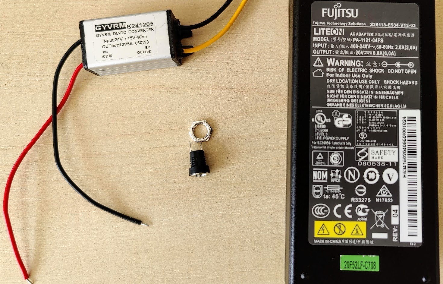
My Play:5 working again. If nothing helps you can power it with an external adapter.
My setup:
- A laptop power adapter (20V - 6A)
- DC-DC converter (24-12V)
- DC connector (female)
The power is enough for max volume and there is no problem.
Thanks for the advice.
You beat me to it by a few hours! Nice job!
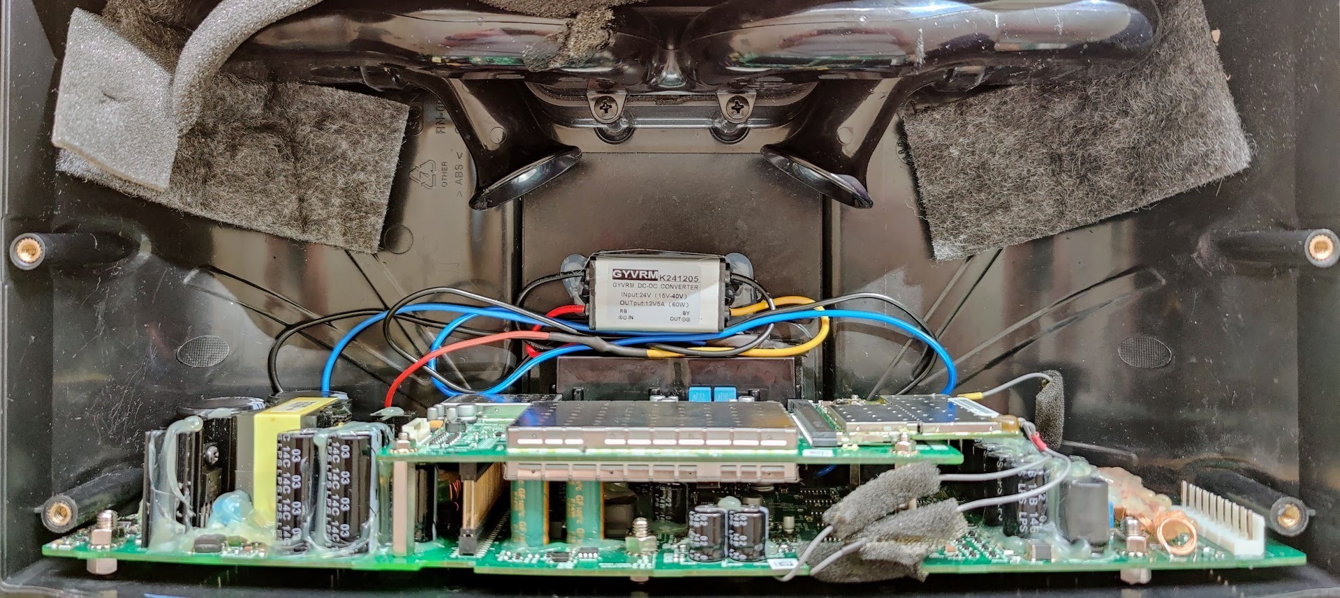
I just repaired mine too. I ordered a 24V/4A power supply very cheap on AMazon… $18CAD https://www.amazon.ca/gp/product/B08NYHM4J9/ref=ppx_yo_dt_b_asin_title_o00_s00?ie=UTF8&psc=1 . I chose this one because it was 250 grams, approximately 95 watts, and the size seemed like it would fit -inside- the case.
I had a few DC-DC converters on hand like this: https://www.amazon.ca/gp/product/B07Y88RTXJ/ref=ppx_yo_dt_b_search_asin_title?ie=UTF8&psc=1
I was fortunately able to fit everything inside the case. I piggybacked the 120V supply to the AC-DC supply from the existing socket, and connected my DC-DC converter at the triple inductor like I had suggested a week or so ago. I opened the power supply case, removed the existing wires, and soldered it all in directly. I had to trim the two bass reflex ports about an inch, and was able to position the brick just below those centered between the two mid speakers at the back of the case. I wrapped the PS brick it in a sheet of foam to avoid vibration. It’s a snug fit, but everything went together perfectly. There is no vibration, and I can’t tell the sound difference between this and an unmodified speaker.
My Play:5 working again. If nothing helps you can power it with an external adapter.
My setup:
- A laptop power adapter (20V - 6A)
- DC-DC converter (24-12V)
- DC connector (female)
The power is enough for max volume and there is no problem.
Thanks for the advice.
Hello, thanks for the picture.
I have-it fixed finally but I do not know the cause. Here it is in words and pictures:
First, small cap (C27854) is not charging from the AC side, those are probably discharge resistors to the remaining capacity in the filtering caps. It’s another mechanism I could not figure out. The C27854 is providing power to the ICE2QS02 driver chip. It goes thru all those small diodes and caps on the edge of the board. The normal behavior on the voltage for C27854 is that is charging up to around 20V slowly and then ( some of those diodes and transistors do that) turns on the power on the ICE2QS02.
Once the chip is starting the voltage is self sustaining to around 13 V, I do not understand from where, maybe from the fly back transformer winding itself.
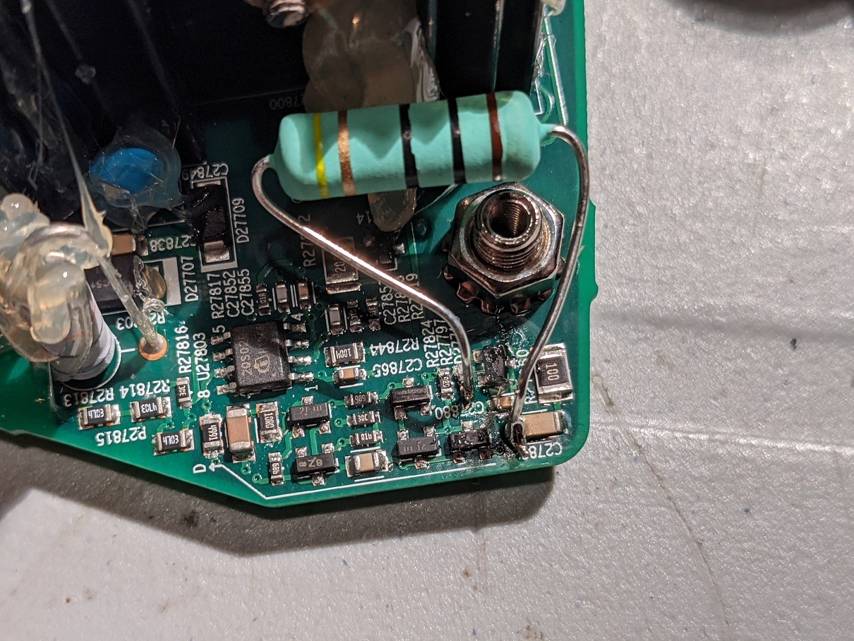
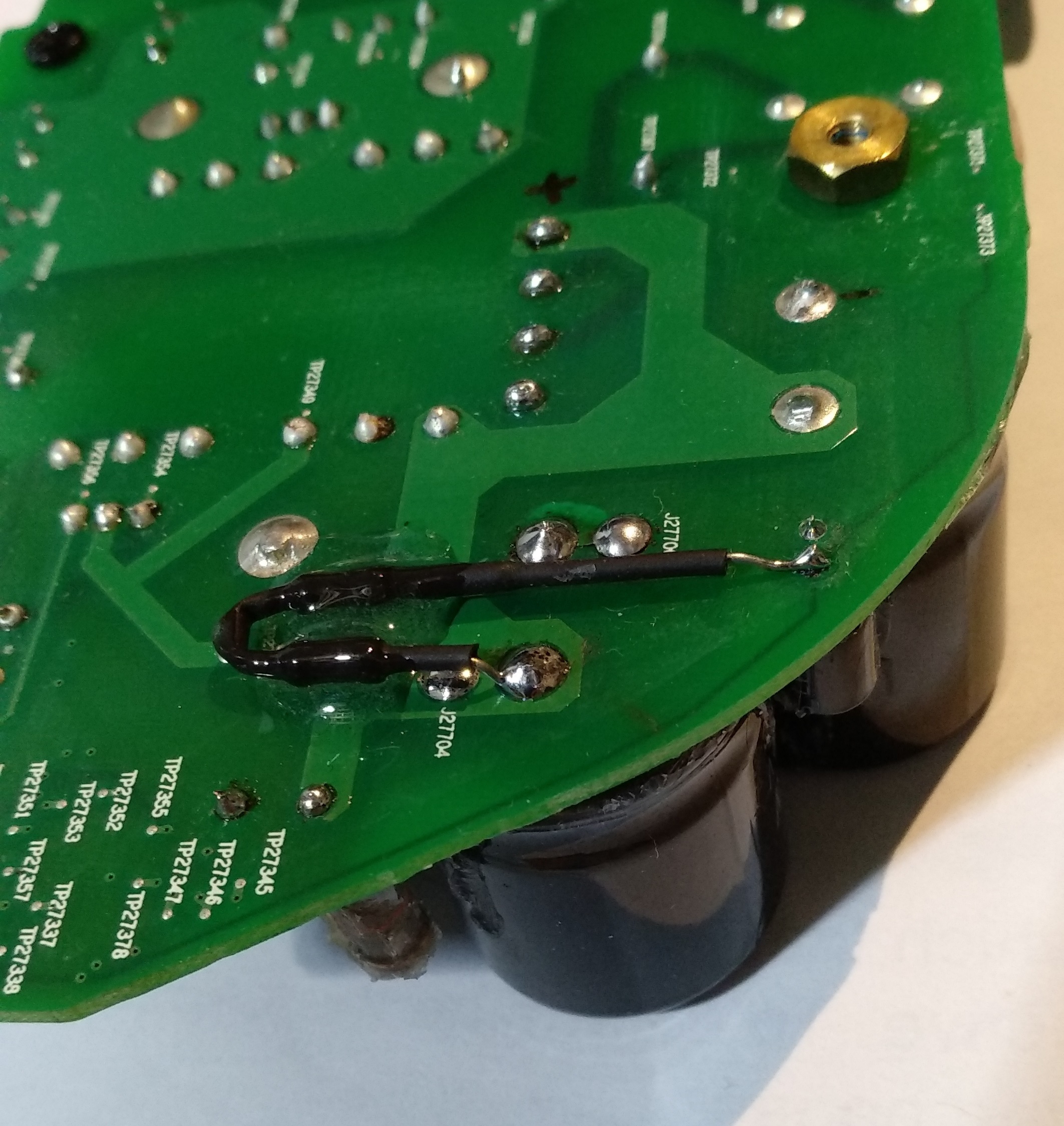
So for me the challenge was to produce the charging of the C27854 up to 20 to start up the IC. I did this by putting 2 390Kohm from the + on the big caps. I monitor the voltage and it’s ramping up slow, like a second or two. After it reaches 20V the IC starts and it self sustain to 13V. It’s 3 days already and still works! meaning there is no other fail. There was no problem in the fuse or rectifier, nothing burned. As you can see the LED turns on with the 2 resistors soldered. This is the story of this fix.
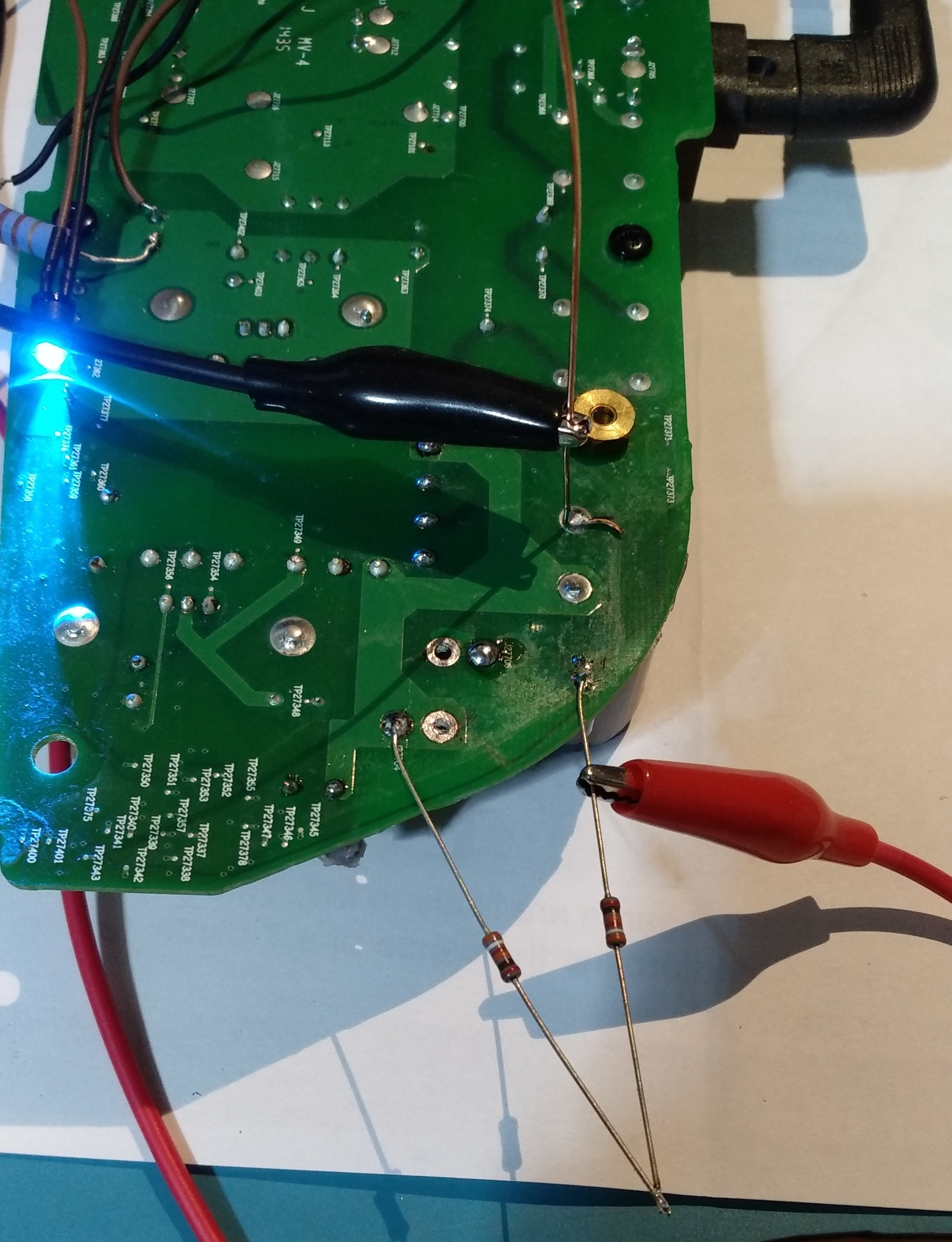
I have no power on pin 7 on ICE2QS02 and when i measure on C27854 it goes from 9 to 18 VDC in a 2-3 second loop, is this the same behaviour as you had?
God news my sonos Play 5 sings
I have changed the small chip that controls the mosfet
2QS02G
I also changed the rectifier MBR20150TC, but I do not thing it was defect. I broke it during the removal. I had to take it out to read the type. And therefore had to install a new one.
also changed 5 pcs electrolytic capacitors 820uf 35V
Hello, I happen to have a Gen 1 with similar power issue, I see on your picture you changed the chip.
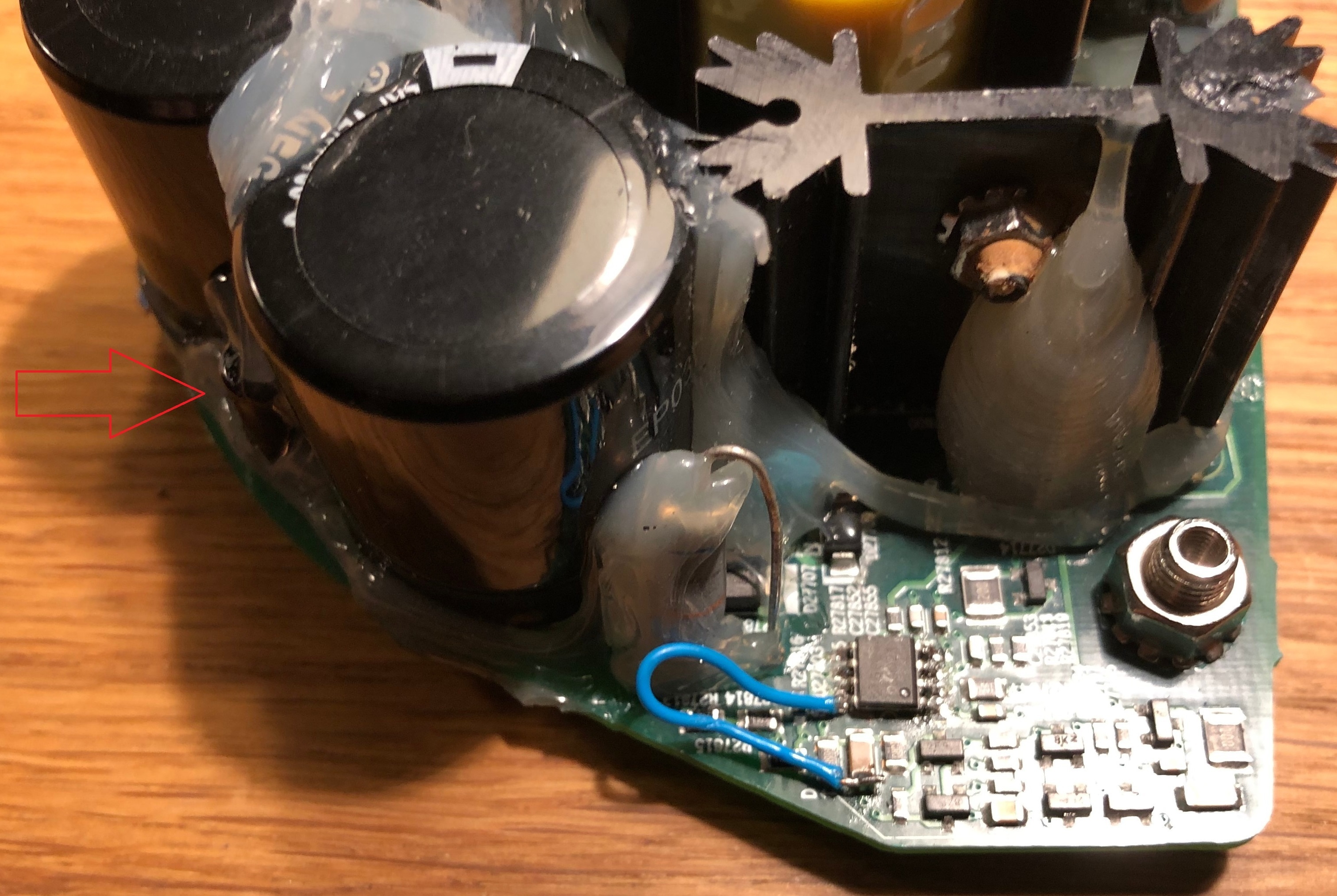
In my case there is no power on the pin 7 of the small driver IC. I cannot figure out from where it gets the power. I manually power the chip with an external 12 V on that capacitor you solder the blue wire. And the power gets back alive! But it’s not self sustaining and as soon as I remove the external Vcc for the IC it goes back to silence. There must be a component I cannot see on the pcb to supply power to the IC. The small cap 100uF 25V has a connection with the power of the driver IC but I cannot figure-it out. Any ideas? Thanks

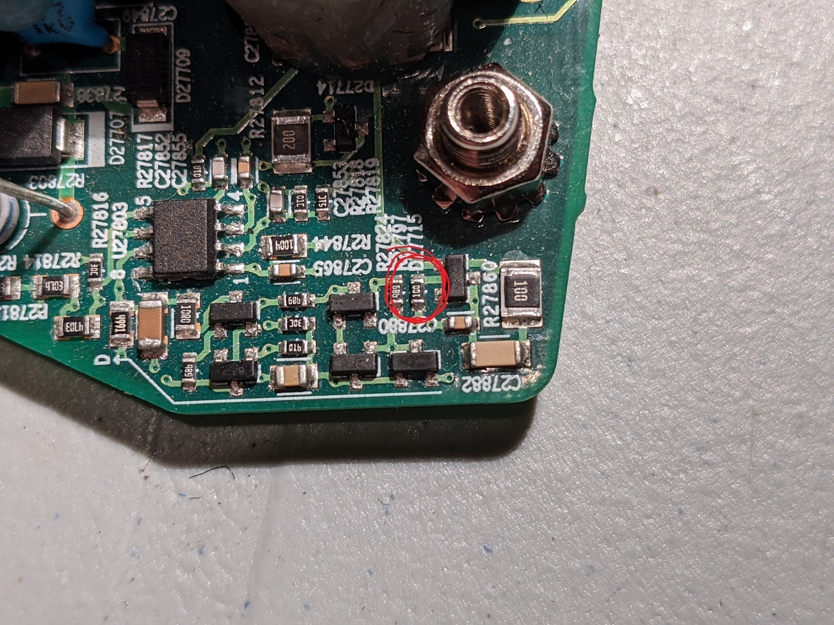
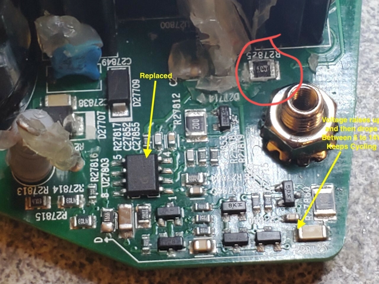
Check this resistor circled in red, R27825. Should be 10 Ohm. In one of my Play 5's it died. Another example of a cheap part killing an expensive speaker
Here is the best I’ve found on debugging Sonos Play:5 hardware issues:
https://sites.google.com/site/sonosdebug/power-topology
The author includes reverse-engineered information about jtag, serial port, connector, and the power supply (including a very helpful partial circuit diagram)!
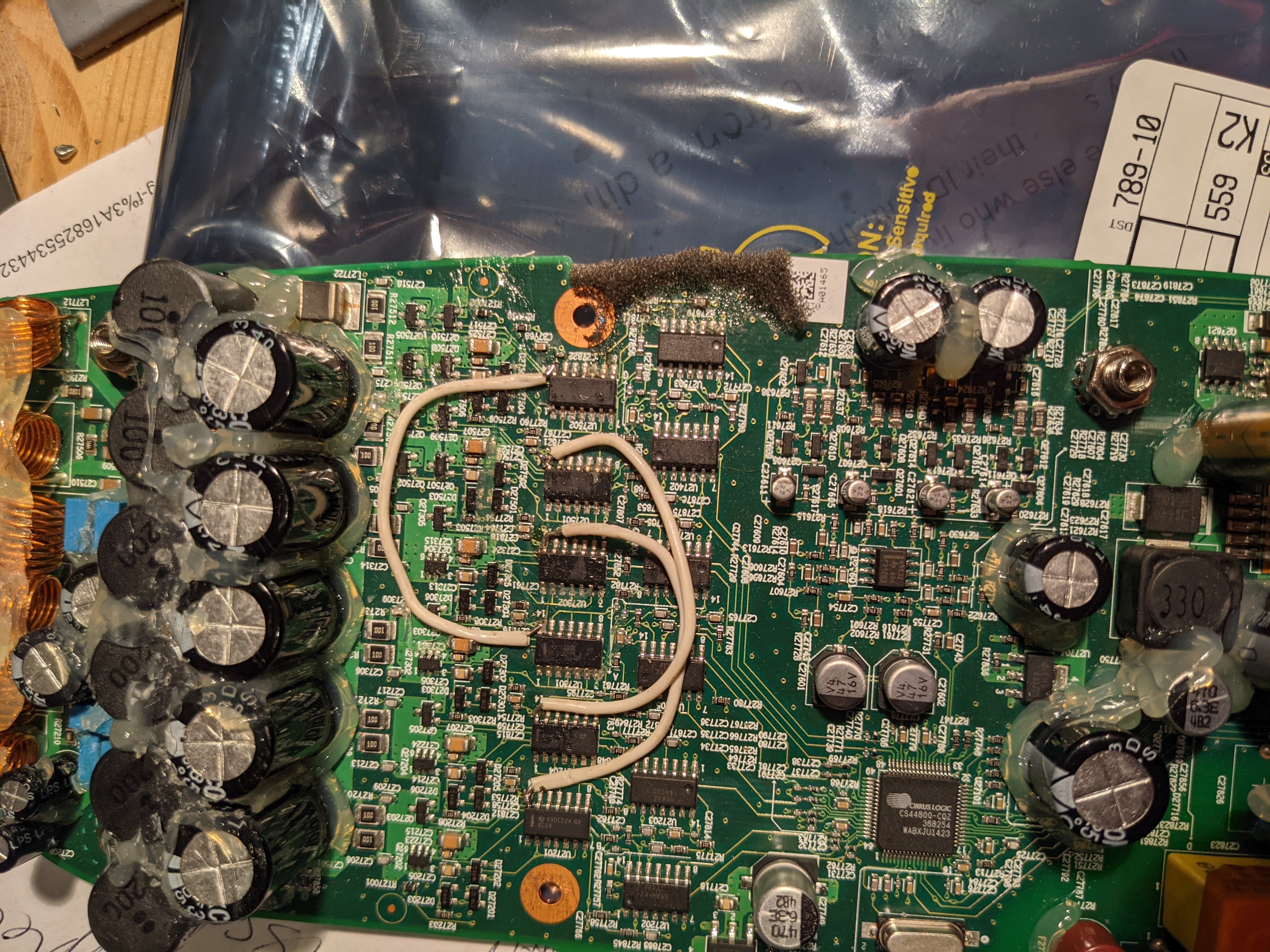
There is nothing about the actual power amp. I have seen a few of these go bad and had only marginal success fixing them. One finding I did have was that a unit with missing bass had some of the driver ICs not having power. It turned out that some of the internal traces had burned out between the driver chips. I jumpered all of the power pins of the 6 ICs together (and all of the grounds too, for good measure), and it solved the problem.
If you have NO sound from the amplifier, then check the biases identified on the schematic and make sure that all of them (12v, 3.3V, 11.1V, 5V) are working.
Hi Tim,
Is your play 5 having issue of very soft volume? Then you jumpered the traces and that fixed it?
Hi. Sorry for the late response. I was locked out… Can't log in
The problem that I had was that of the 5 speakers, some were working and others were not. I found that some of the driver chips did not have power and was able to add power to them… after which it all worked again. Here is a picture of what I jumpered. I think that this was not the complete job… but you should get the idea from here.
Thanks Tim. Unfortunately my play 5 issue is not the same issue. All the pins have 5V to it. Headphone out is working fine, just the all speakers have a very faint sound.
Faint sound at max volume? Check this.
Im going to piggyback onto this discussion to see if someone can help me out.
I have a Power supply issue with an issue on the switching side.
The unit has no power.
Replaced most of the power side caps, rectifier, fuse, FET IC Driver, FET, (Also smt 120K resistor near the rectifier was blown.)
I feel like im close, but I have this problem where the voltage starts at 5v ramps up to 15v and then bumps back down to 5v to repeat the process. Thought maybe a diode, but I cant find it.
When i remove the little 25v 100uf Cap between the two big filtering caps, the fluctuation goes away. Still get no power though.
Any Thoughts?
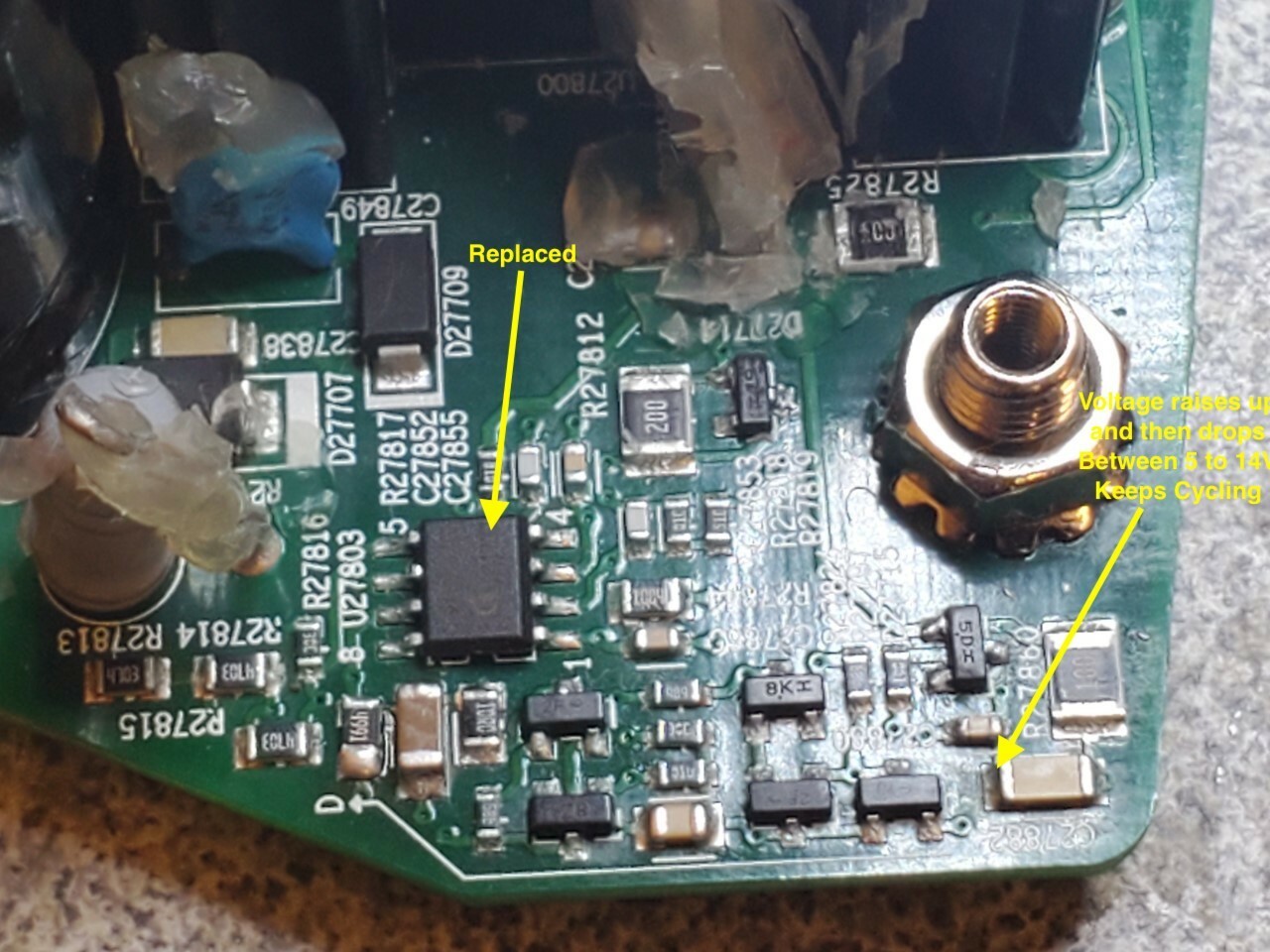
Check the resistor R27825, this is 10Ohm I believe. Normally not visible due to the extensive glue on the board. I had a similar case where there was no power at all. I didn't check in detail but I think this resistor is part of a control loop. Another issue where replacing a single resistor restores services.
Folks, I see some questions regarding Play 5 with low sound at max volume. I just created another post with a fix for this issue.
A definite maybe.
- You need to worry about wattage as much as voltage. You would want to use a supply with enough wattage. 95% of music I play is not so loud that I can’t have a conversation around it… That kind of level would be fine with 20 watts. I just looked at a Lenovo laptop adapter. It is marked output 20V 2.25A. That works out to 20*2.25=45 watts (before anyone jumps in to say this isn’t right -- it’s close enough for this conversation). Most laptop adapters should have enough wattage to work
- Most amplifiers will operate with a range of input voltages. You may get clipping or dropouts if you try to turn the volume up to a point beyond what the power supply can manage. Below that level it would work ok. If something is designed to work with 24V, and you feed it 20V, then you can expect a maximum output wattage of about 70% of the designed output. (This is calculated as (20/24)^2 ).
- Sonos is not necessarily “most amplifiers”. I have done a ton of work with ZP120 repairs. Those operate with several internal voltages. In particular, the audio section works at about 15 volts, until you turn the volume up... then a 36 Volt circuit comes on. The ZP120 has a voltage sensing circuit in it, and if the 36V circuit does not activate properly, it reports an error and ramps the volume down to about 10%. My experience is that this circuit must be 36V -- not 30V and not even 40V.
- I don’t know if the Play:5 has the same kind of voltage detection as the ZP120 or not. I was once able to disable the voltage sensing circuit in a ZP120 and drive it with a different voltage, but it isn’t really a practical fix for the ZP120, let along the Play:5
So the upshot is that you won’t damage anything by hooking it to a 12V and 20V supply (instead of 12V and 24V). The worst is that it doesn’t work (but it won’t do any permanent damage)
Some more on wattage…
Sonos speaker wattages are not (as far as I know) published. It’s also hard to reverse engineer, since it is not driving 1 or two simple speakers. There are 5 separate amplifier circuits for the 5 speakers. I have measured the 5 speakers, and they seem to be 7 ohm tweeters, 3 ohm mids, and 3.6 ohm bass. There is also some crossover and equalizer circuitry. If I make some very coarse assumptions, then I calculate a maximum wattage of 200 Watts. Paring this back for crossovers, as well as frequency impedance curves, I’d be surprised if a 70 Watt supply wasn’t more than sufficient. (and if you’re using a 20 Volt supply, then apply the above 70%, and you’d be ok with a 50 watt adapter). This seems to me to be more than reasonable from another angle… when I look at the circuitry of the power supply, it ‘seems’ to match these kinds of numbers based on its physical size.
The space is pretty tight inside the play5. I don’t think you can fit in the power supply.
True. Another option is to have the replacement power supply in a separate enclosure with just the low voltage 12v/12v fed in through a small hold in the back. The supply can be hidden quite far away from the speaker, if that's what your setup requires.
Yet another option…
24v ‘brick’ power supply… https://www.amazon.com/JOVNO-100-240V-Transformer-Converter-5-5x2-5mm/dp/B0875ZSKGR
And this installed inside the enclosure: https://www.amazon.com/EPBOWPT-Converter-Regulator-Voltage-Transformer/dp/B07V6X6L89
Is there any problem if use a laptop adapter 20V instead of 24V input? I have some adapters here and don’t want to buy any extras.
The space is pretty tight inside the play5. I don’t think you can fit in the power supply.
True. Another option is to have the replacement power supply in a separate enclosure with just the low voltage 12v/12v fed in through a small hold in the back. The supply can be hidden quite far away from the speaker, if that's what your setup requires.
Yet another option…
24v ‘brick’ power supply… https://www.amazon.com/JOVNO-100-240V-Transformer-Converter-5-5x2-5mm/dp/B0875ZSKGR
And this installed inside the enclosure: https://www.amazon.com/EPBOWPT-Converter-Regulator-Voltage-Transformer/dp/B07V6X6L89
The space is pretty tight inside the play5. I don’t think you can fit in the power supply.
True. Another option is to have the replacement power supply in a separate enclosure with just the low voltage 12v/12v fed in through a small hold in the back. The supply can be hidden quite far away from the speaker, if that's what your setup requires.
The space is pretty tight inside the play5. I don’t think you can fit in the power supply.
Hi,
how much power needs play5? I found a power supply. If it is fits (physical and electrical) I will buy and install it.
Size: 16 * 10 * 4cm
Can you tell me which pins should I connect 24 and 12 volt in play5 mainboard?
This one is at amazon.de 14€, I think it is fair price.
That power supply looks like it should work. I don’t know what the maximum rated power of the Play:5 is, but that one looks like 70 Watts… For me that’s more than enough volume.
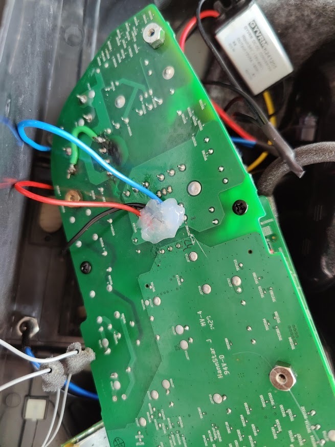
As far as connections… There is a triple inductor between the power supply and the downstream electronics. The purpose of that inductor is to filter noise. You could hook up to either side of the inductor (since your power supply will have filtering in it), but I would hook up to the inductor on the power supply side. This way, the outputs from your supply will pass through the inductor and be filtered. I’ve annotated the 12V, GND, and 24V in the attached image.
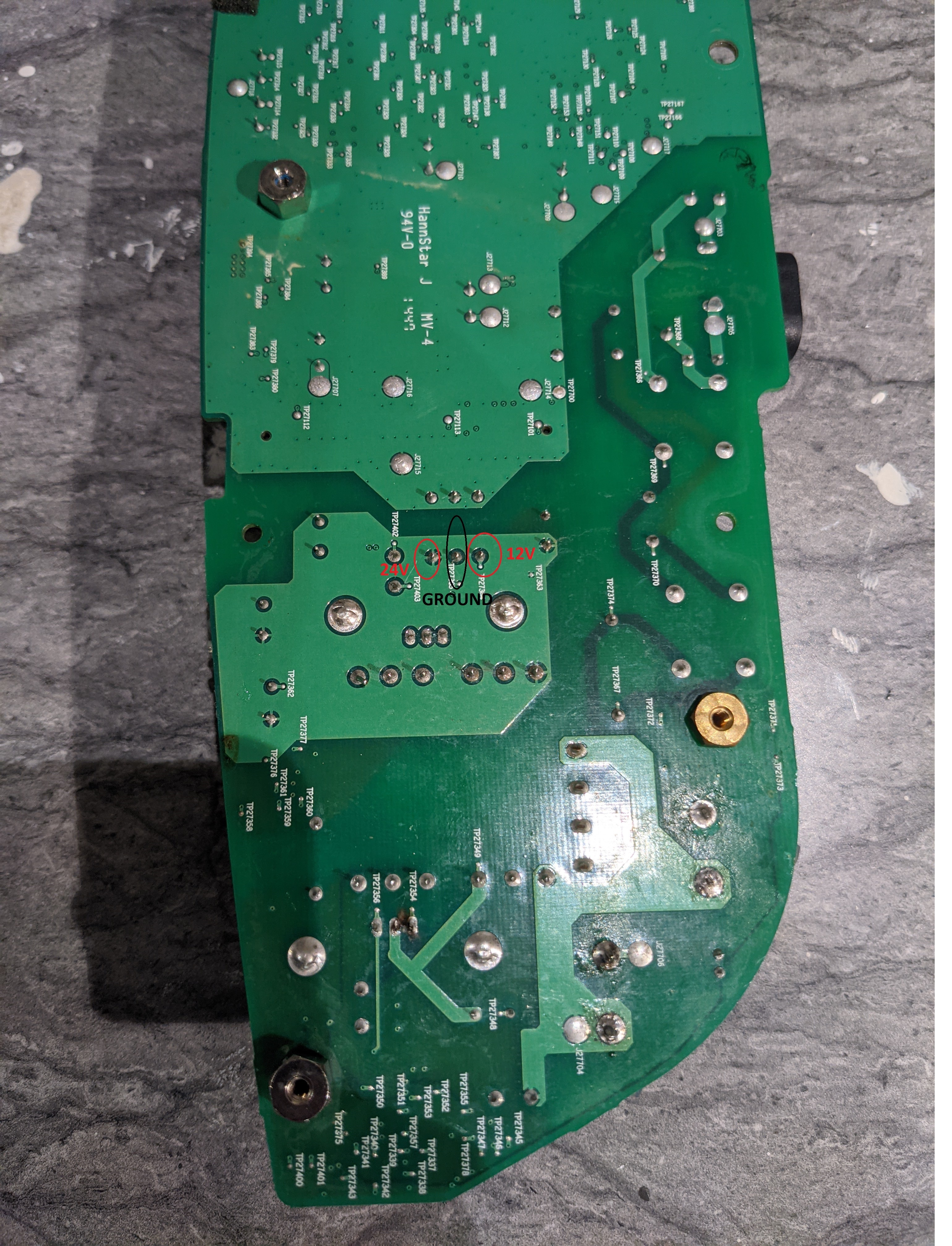
There is a small chance that the problem with the power supply circuit will prevent just adding power to the board. In this case, you would need to separate the built-in power supply from the downstream components. I would do that by just removing the inductor (desolder it, or cut the legs of it off and remove it). If you do this, then you will need to connect to the three connection points directly above the ones that I marked (the order is the same as I labelled).
Good luck!
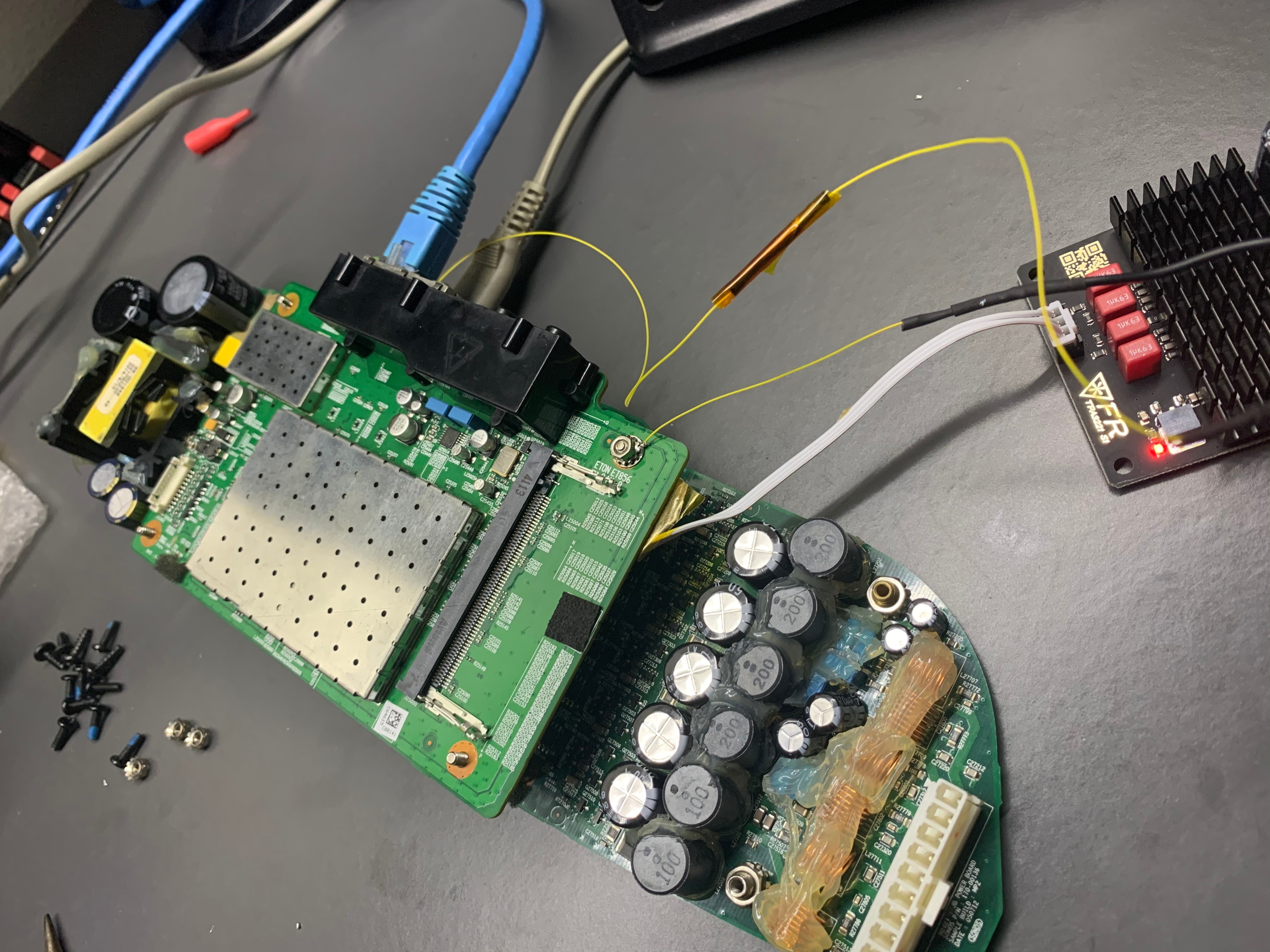
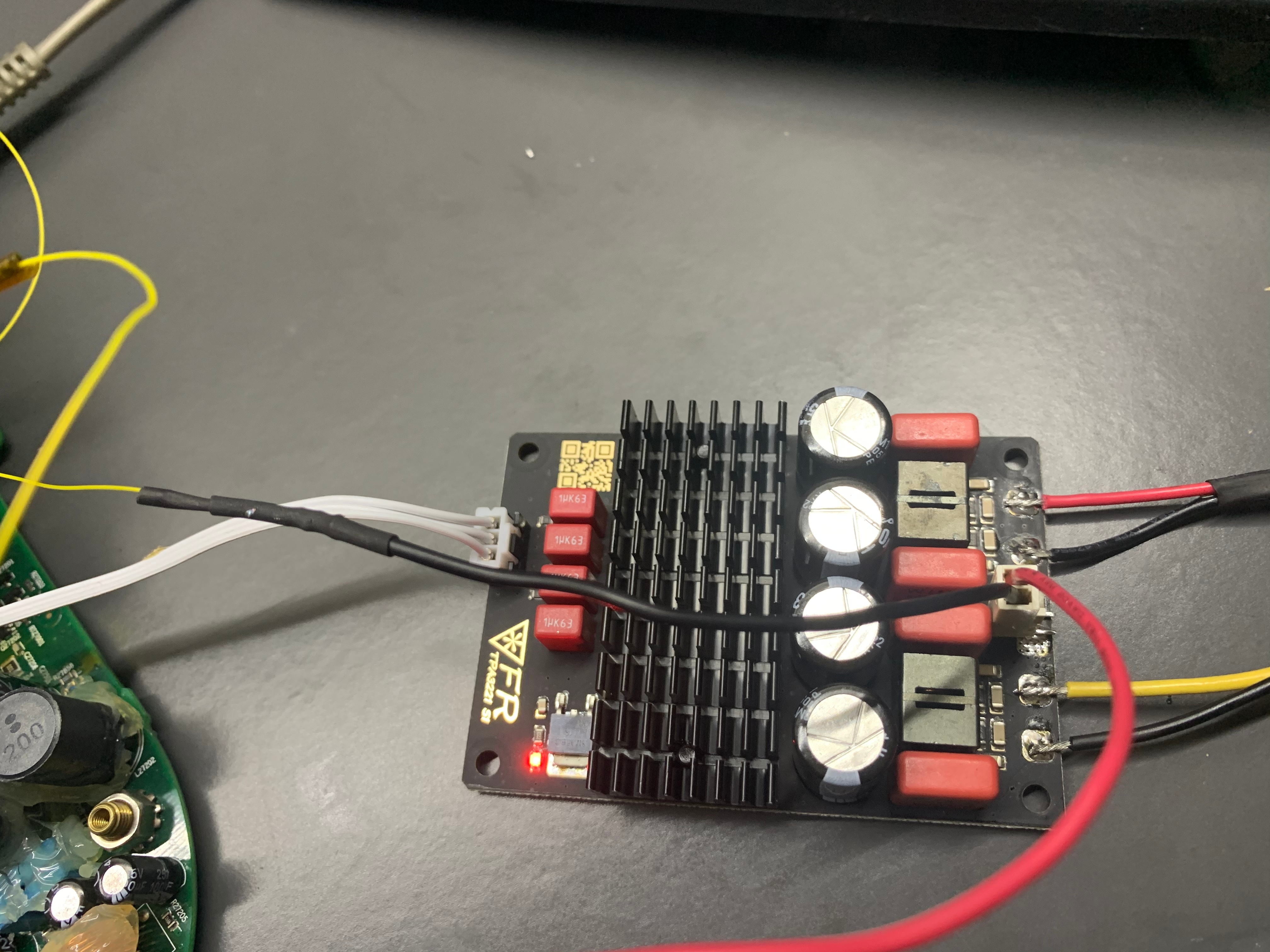
Last resort is to add in a class D amp to it. Not ideal at all, but at least, sound is back.
How was the sound out of that class D Amp?
If decent, what brand model, and where did you connect? It looks like directly off of the wifi/controller board?
At low volume, I can hear the static noises. That will go away when I increase the volume. I got it from AliExpress.
Running at 12V and I may try to use 24V if that helps on the static. The connection is to the headphone out on the wifi board. Hope that helps.
Last resort is to add in a class D amp to it. Not ideal at all, but at least, sound is back.
How was the sound out of that class D Amp?
If decent, what brand model, and where did you connect? It looks like directly off of the wifi/controller board?
Page 6 / 9
Enter your username or e-mail address. We'll send you an e-mail with instructions to reset your password.