The amp has no power. Is there an internal fuse for this unit?
Has anyone taken one apart?

Page 8 / 17
Any new updates? I just bought a dead ZP120 on eBay and will be diving into it next week.

Sotisg69,
Hope this helps.
Hope this helps.

No updates. Keep us posted on your repair efforts.
Hello gruve2ths excellent jobb back there once again. Iknow i almost kill it
I can se that the pin 8 from Ic goes to R15543
pin 9 ? the same?
pin 10 R15544
but i missing
pin 3,4,5 and must be sure 10,11,12
Please !:P
I can se that the pin 8 from Ic goes to R15543
pin 9 ? the same?
pin 10 R15544
but i missing
pin 3,4,5 and must be sure 10,11,12
Please !:P
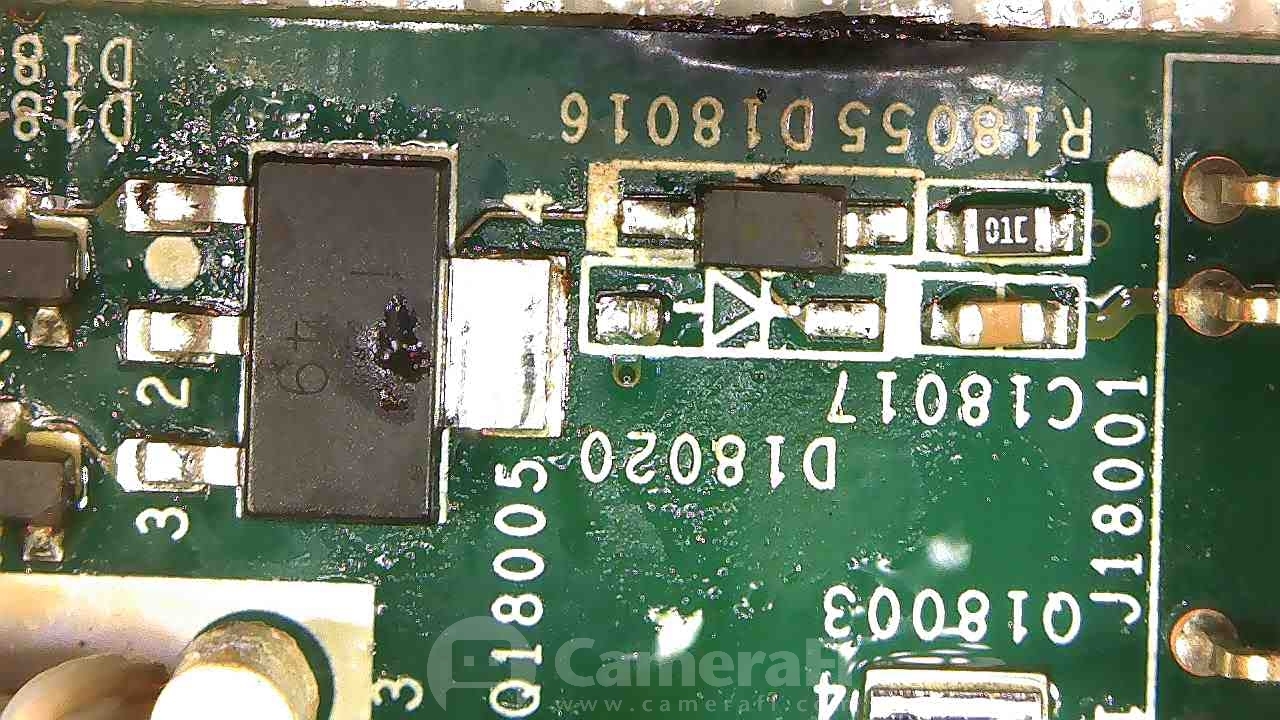
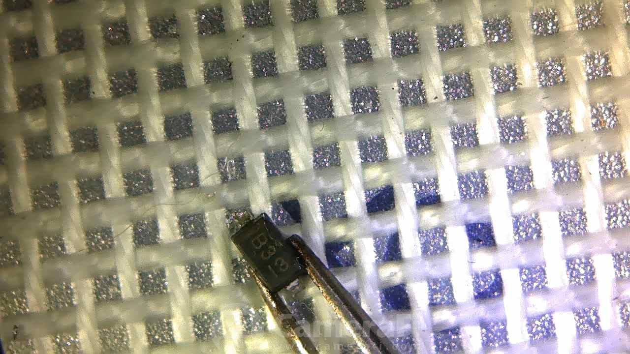
This is right above the smaller connector of the riser board (j18001). I found a short on pins 2/3 of Q18005 removed it and eventually traced it to a shorted D18020 right in front of it. D18020 is labeled D3 with a sideways 13, which I think is the date code. I believe it's a zener diode but not sure. Will try a few things and report back.
I repaired the one I am using. It was a no power failure as well. It appeared to have some sort of liquid damage on the logic board that shorted an output of the power supply. I fixed that damage on the logic board, then started looking through the power supply. What I found was a TO-220 (or similar) package dual schottky rectifier was now shorted, also the main bridge rectifier on the front end of the power supply was also a short. Once replacing those 2, the dim-bulb went bright then dim and the indicator started flashing. And I friends was in business!
I liked the ZP120 described above so much that I just bought another ZP120 with the same fail description. I crack it open tonight. Will update this forum when I get it working.
I liked the ZP120 described above so much that I just bought another ZP120 with the same fail description. I crack it open tonight. Will update this forum when I get it working.
sotisg69,
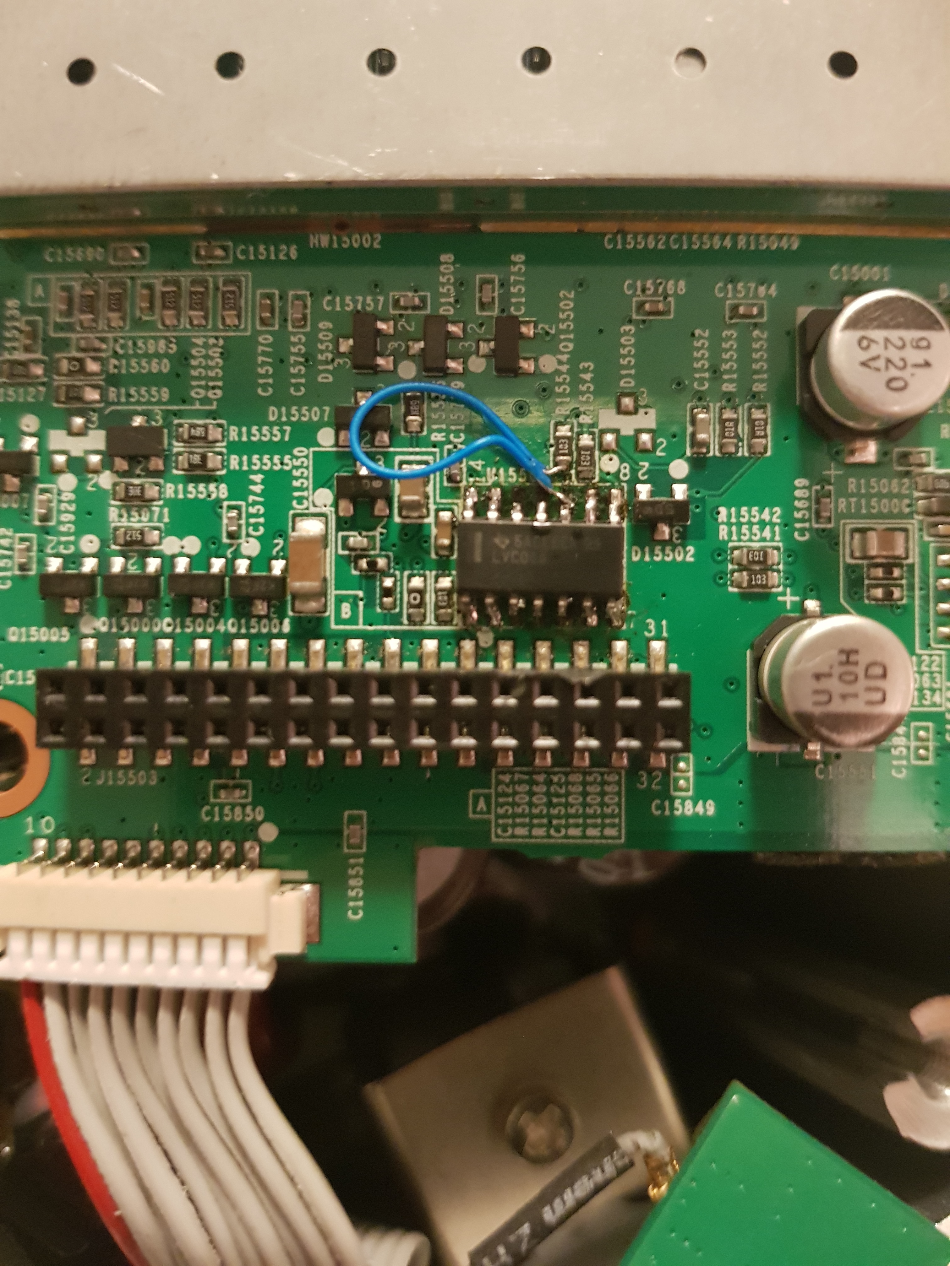
You have to zoom way way in to the pictures that i attached to see traces.
As you can see most of the pins of that IC via down underneath the pads so no visible traces can be found. I suspect the inputs to that chip all come from the controller. The outputs are likely that connector next to the chip.
Has anyone taken one apart?
Gruv2ths
Is there a another way to figure that out?
I will do som measurment tomorow and let you know .
😃
Is there a another way to figure that out?
I will do som measurment tomorow and let you know .
😃
Dose any one know where is the fuse ?
Hello gruve2ths.
Do you think you can help me locate the missing pins3,4,5 ,11and 12
Best regards Sotis
Do you think you can help me locate the missing pins3,4,5 ,11and 12
Best regards Sotis
The fuse is a small orange cylindrical part by the input connector. Through hole, axial lead. I wouldn't just swap it out, it will blow again. If you comfortable around high voltage, I would try the dim bulb.
Sotis,
Sorry this took a long time.
So can't help you with all the pins, but but was able to find continuity for a few.
The continuity is between the driver ICs output to the 32 pin connector next to it.
(look at the silk screen around the connector, you will find the pin number guide there)
IC Connector
2 4
4 5
8 23
Sounds like you just may need to get the 36V power converter enable connected.
Maybe if the above doesn't help, You can look at the datasheet for the IC and look at the input pins and see which ones go high when you push play. and go from there.
There was another guy on here with the same symptom as you and I think he gave up. Not sure what causes that.
I finally got back to this -- checked all the DC voltages and they all match your reference. Even with my fluke truerms I didn't validate the secondary but I am guessing I referenced to the wrong point. The DC busses all look OK.
I am thinking to pop off the shield can on the logic board to get at the UART. Any other thoughts? Still a solid white LED.
Is there any YouTube video that shows how to replace the fuse ? Pls add the link - Tnx

It’s been a while for me, but I’m revisiting some old dead units. The first one I picked up has already stumped me, and I know it shouldn’t, as the problem seems like it should be a slam dunk to fix.
ZP120 with no power. With a dim bulb, it lights then fades. When I look inside, the main rectifier is fine. I have 162V on VMID (good), and 162V on VPRI (BAD). I replaced the shottkeys, and the diodes and capacitors all seem ok. What am I missing??

As I cannot find a retailer selling the K13A60D, I am looking for an equivalent n-channel mosfet. I came across this one ;NTP360N80S3Z. The only main difference is the avalanche current, which is 2A instead of the 13A of the K13A60D. Would this matter? My guess is yes, but I would like another opinion by more specialized people in this forum. Also the turn-on/off times differ a little. They all seem to be shorter on the equivalent mosfet.
I went ahead and ordered 2 2DRAM parts since I don't know which is bad. Anyone tried this replacement? I might have to remove the shield. If not I'll remove the parts with hot air and then put the new ones down.

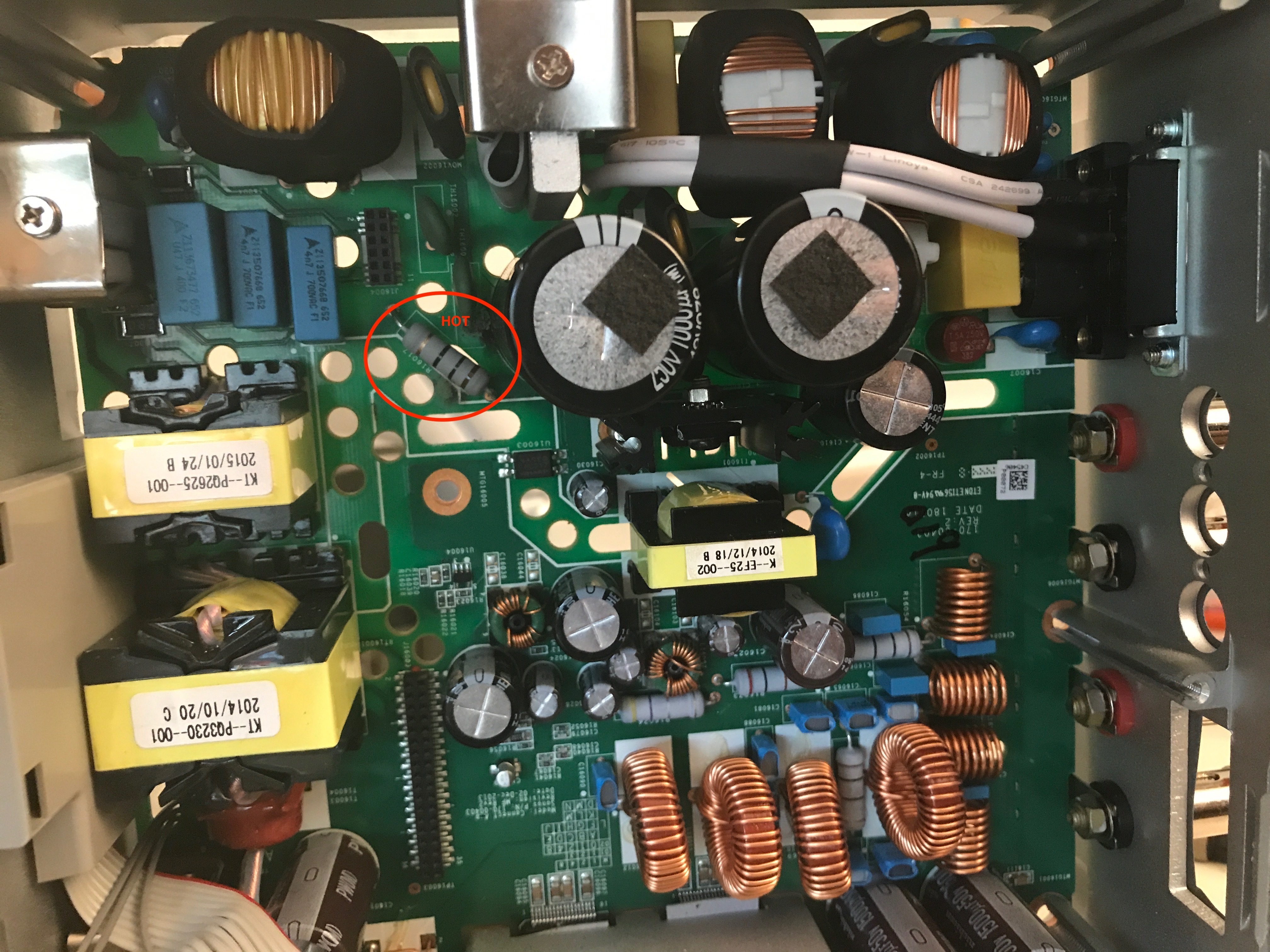
@gruv2ths - Outstanding job. I have a SONOS ZP120 that unfortunately got wet and the power blew a 10ohm 2W resistor (R16017). I replaced it. I plugged it in and that resistor blew again... and it looks like it took out one of the SCK054 thermistors (TH16001). The thermistor was a wee bit charred however it tested 5ohms which is the normal rating. I have ordered new ones since I don't trust anything that got charred, but they will take 10-4 days to get from China... nobody sells em here in the US.
I tested the rectifier on the input side (the one clamped to the chassis) and it looks good. I tested the diodes and those look fine. All caps are looking good too. The fuse is fine... it never blew.
I am guessing the problem lies downstream from the components listed above. A couple of questions...
1 - That TO-220 you mentioned... is that the one that has a heatsink screwed into it and standing up? Do you know the code on it or type as I cannot tell.
2 - What is the secondary rectifier your are referring to? I would like to test mine to see if its checking out (or not).
If you have any recommendations, I would love to know how to any techniques are parts I should be checking on the PS board... I am thinking this is simple... but I am having a tough time narrowing it down.
Thanks!
Never done this. Looking forward to your results!
Slight update... as I am waiting for the SCK054s from China... I decided to check everything in the path. All looked good except for the 115/220 red switch. It showed 0L on the meter at 115. I switched it to 220 and it was 0L. Switched back to 115 and had continuity. My guess is when the unit got wet, something happened to that switch and hence it made the unit look like it was supposed to be connected to 220v. I followed the trace and with 220v, it all leads to the blown resistor and thermistor. But with 115 active (continuity) it throws in a drop through the varistors and the other path meets it. Just a guess, but it appears that the 220v setting may have caused the current consumption along the resistor/thermistor path to exceed what it was normally supposed to see. That may be a red herring and I will find out when my thermistors arrive... but I thought the 220v setting running on 115v wouldn't hurt the PS...worst case it just wouldn't fire up. I'm just guessing that perhaps it does indeed have an impact on a PS.
Well, I was able to change the DRAM out without much issue. I used kapton, some foil, and the hakko hot air rework. Then I cleaned the pads and put new parts down. Unfortunately, it did not fix it. That pretty much confirms that the issue is probably a cracked solder ball under the BGA, or head-in-pillow or some other similar type defect. I thought about putting it in the xray but it is so hard to see some of these defects and regardless of what I found, it was not repairable.
Ok... I tested the thermistor and under heat etc and it seems to test out ok. Due to the excellent posts in this thread, I decided to put together a dim bulb tester so I would stop blowing components. Great idea...
So I decided to fire it up under the dim bulb tester after replacing the 10 ohm resistor and putting back the thermistor... and the light bulb shined brightly so I still have a short somewhere....
I cut the power and decided to test for heat. Again, that resistor was getting hot (and was saved due to the dim bulb tester).
Here is the resistor and it is hot (notice the circle labeled hot):
Anyone have ideas on how to hunt down the short?
That's a bummer. Which Hakko do you use? I need a hot air tool. Crazy range in prices.
Remind me what your Amp was doing, or how it was failing?
Remind me what your Amp was doing, or how it was failing?
I recently had another ZP100 go out, so I took the CPU board from that device and swapped it into the first one. I powered it up, RJ45 ports work, it gets an IP and shows up on the Sonos app (as the “donor” ZP, naturally). However, when I go to stream anything (local music or through a service) it tries for a while & then I get a message like “Can’t play this station” from the app. Is there something else I need to do on the player to get it to stream properly?
When you say that you had another “ZP100 go out”, how did that device fail? If you moved the logic board from that device to the one that had the blown ethernet, perhaps it is broken in another way?
Do other music sources work? Or does the device alternately flash white/orange? One easy way to test comms from your phone to the device is just to mute the device from your phone. If it is receiving messages then the mute light will come on.
Page 8 / 17
Reply
Enter your username or e-mail address. We'll send you an e-mail with instructions to reset your password.