The amp has no power. Is there an internal fuse for this unit?
Has anyone taken one apart?

Page 6 / 17

Gruv2ths, thanks for the quick reply. See picture attached. I have lifted one side for both diodes and 36V rail has no shorts.
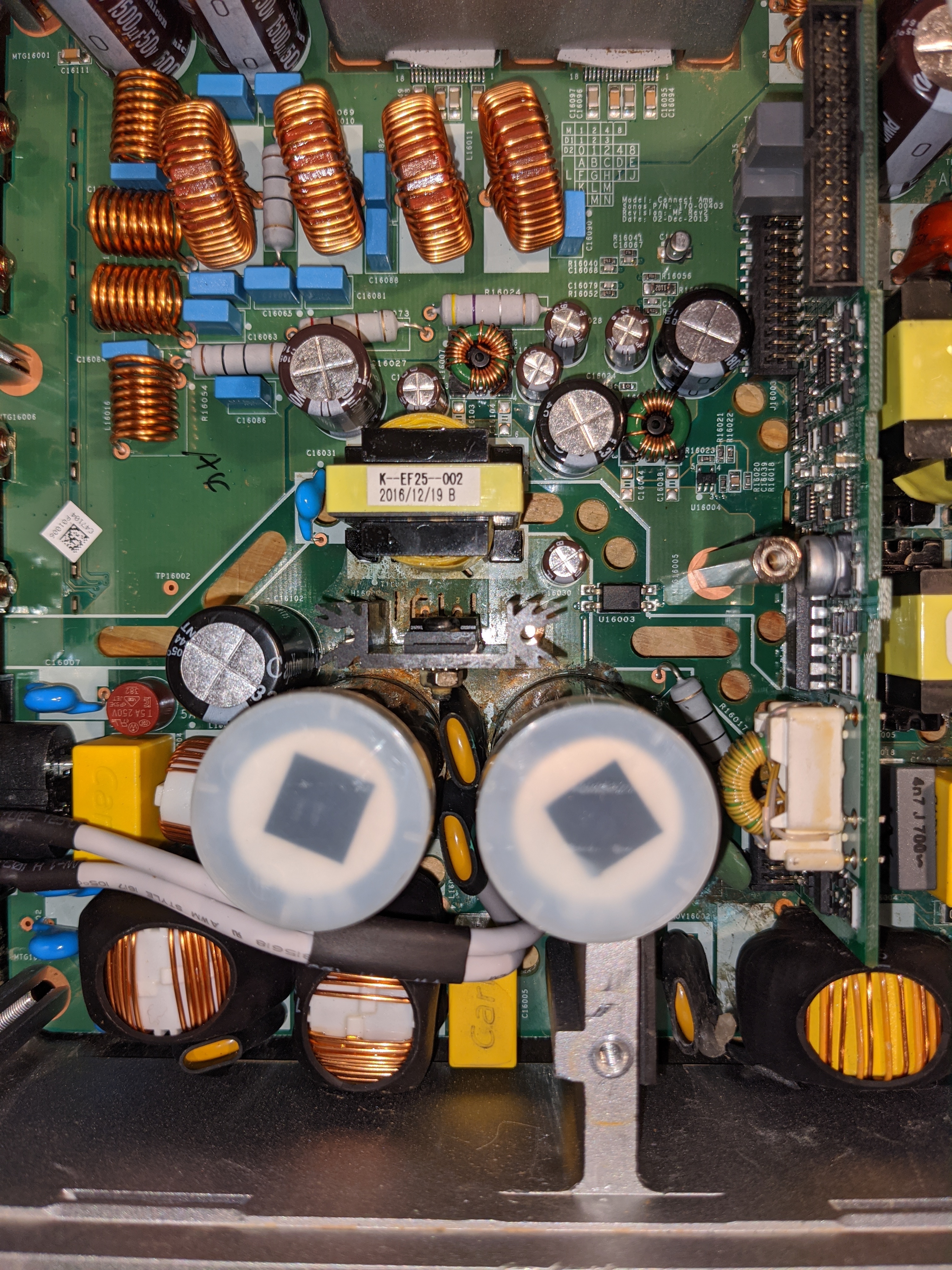
Checked a bit more....smell wasn't semiconductor but electrolyte. The 33uF 400V capacitor died (C16102). See photo....I think I will just replace all of them. Clearly some ageing of parts.

Hey Tim, You mentioned that you replaced the caps, does that include the big ol’ pair of electrolytics?
Also the diode bridge (4 pin part that clips to the chassis). Are those new?
Hey man, no problem, I just happen to be at my computer. I think those are opposite the 36V supply FETs.
I think those are protection diodes for the FETs, but not too sure. I would think since they are primary side and shorted that you would be blowing fuses?
This is not so common in my experience that they are indicative of another problem. This is probably the first layer of your onion. LOL
Are you using a dim bulb in series with your 110Vac? You should be if you are not.
Remove the shorted parts and see happens. Do you have a short between the 36V test point and the RTN36 test point?
thanks! I found a short on the mosfet side, but to be sure, I also want to replace the schottky diodes on the other side… Do you have any idea on what replacement part to order for these?
If you are referring to the pair of TO220 Schottkys mounted to the case, those are 10 Amp 100 Volt. Part number SBR1010CT
the short I mentioned was not correctly diagnosed. So No short is detected on the mosfet side. Schottky diodes also seemed ok after removing them.
I build a dim light bulb tester, replaced the 10 ohm resistor, and removed the MOSFET’s and schottky diodes. When plugging the device in, the bulb goes full brightness. I am using a 53W bulb. Also plugged it in With the input/network card removed. Lamp still goes on… Owner told me the damage was probably caused by water as the amp was placed under a bathtub… Any thoughs? Not sure If the PWM is still ok But as I replaced it last month, it should be.
I think that is the vbias cap to the integrated pwm chip. Not common but happens.
2 different circuits from the diodes you showed earlier. Another layer of the onion..
2 different circuits from the diodes you showed earlier. Another layer of the onion..
Hey man,
No, that doesn’t tell you anything.
I would check for the bias voltages.
They must be there, that is how the led is coming on.
maybe they only come up for a short time.
Look for missing voltages. Be careful. High voltages at the input.
Thank you, Gruv2ths! I’ll try to have a look again for any damages and then try to measure. I have been doing a lot of repair when it comes to retro video games but that’s always 12v or less so I am a bit nervous when it comes to 230v.

Thanks for replying gruv.
I had another look today. I removed the rectifier and checked it out of circuit - it was fine. I removed the three caps near the mosfets - they were fine. I removed and replaced the two mosfets with new ones. I checked the two large electrolytics in circuit and they seemed fine.
Then I started poking around and was trying to reverse engineer the circuit. I couldn’t see a lot of the components well, and not all the traces either, given how tight some components were. I ended up removing the choke just downstream of the rectifier. I held the board up to some bright light and could finally see where the positive trace was running. It was leading back to Vpri via a varistor. BUT… the trace was dead! I couldn’t see the trace as it was under some paint, but this unit was water damaged and my guess is that it was probably rusted out.
So, I put everything back in (the choke was a pain), ran a jumper where that trace should be… and now I had 320 on Vpri.
Unfortunately I don't have any biases on the secondary. It looks like more damaged parts - probably the oscillator. Well… at least I am making some progress. Here’s a picture of the likely problem I have to fix now…
First thing I checked was the fuse but that's still fine. Out here we have 230VAC 🆒
Need to check for a bulb, these things are getting hard to find with LED taking over and thr old bulbs no longer on sale.
So far I see no shorts. I just ordered all the parts, including 2x 1000uF. They seem a bit swollen too. I will report back once I have replaced the parts. That will be 2019 for sure 🙂
OK cool, the bulb is worth the work to get running, will be helpful for anything off line you test.
I have had a hell of a time getting those 1000uf caps in the right case sive. A little wider and they are too wide, same goes for the height.
Looking forward to hearing how the parts change works out.
If you don't mind me asking, where are you? I am in Texas.
I have had a hell of a time getting those 1000uf caps in the right case sive. A little wider and they are too wide, same goes for the height.
Looking forward to hearing how the parts change works out.
If you don't mind me asking, where are you? I am in Texas.
Gruv2ths, I measured the 1000uF and have ordered SLPX102M200C4P3 CORNELL DUBILIER - diameter 25mm, height 45mm. Not really high quality but you are right, space is tight on the pcb.
By the way I'm in the city Leiden in the Netherlands. Also have 2x broken Play-5's lying here (1x PSU ticking and 1x amp stages blown up) . Ever done some work on those?
By the way I'm in the city Leiden in the Netherlands. Also have 2x broken Play-5's lying here (1x PSU ticking and 1x amp stages blown up) . Ever done some work on those?
Hello, im from Germany and need your Help.
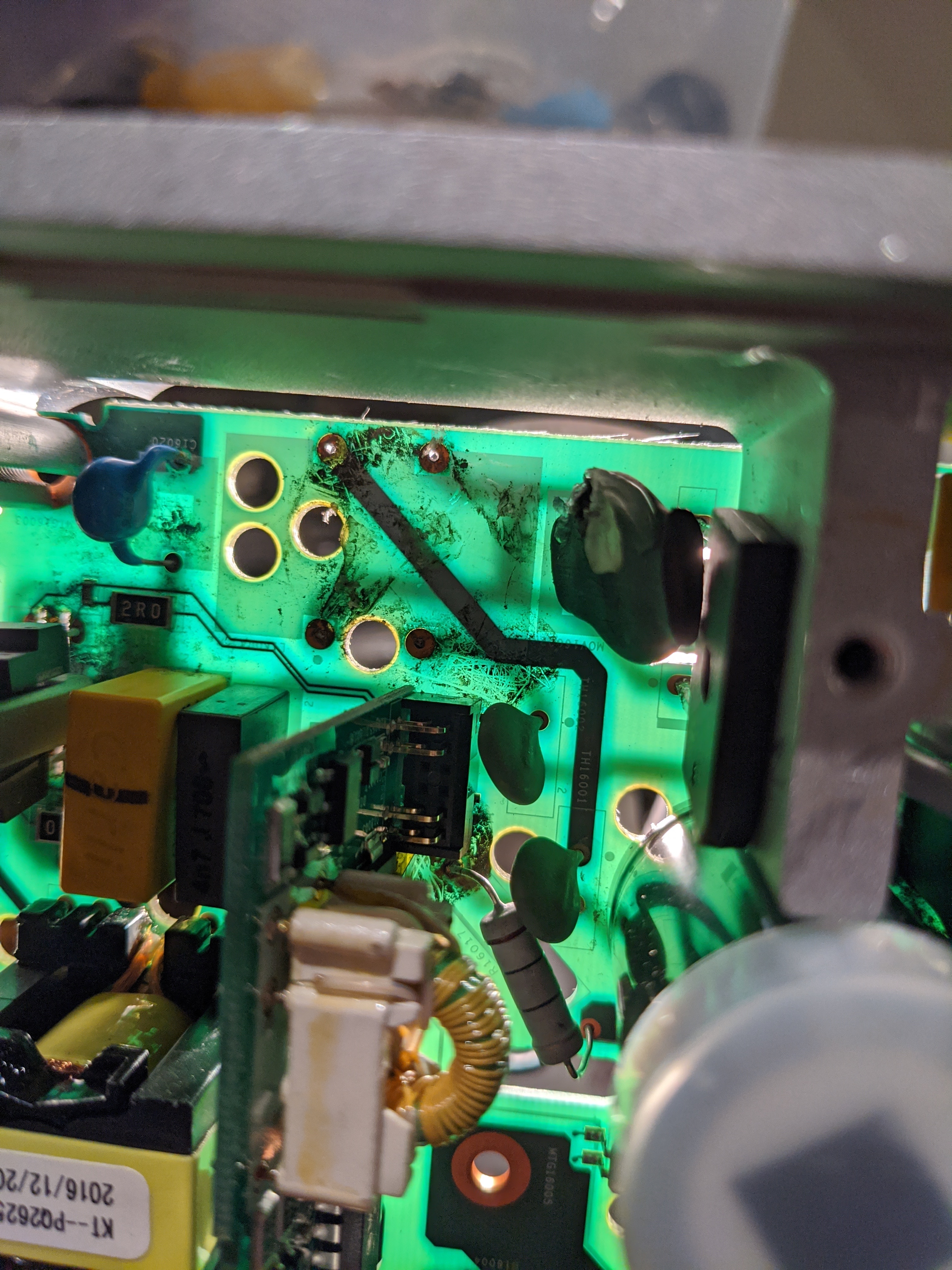
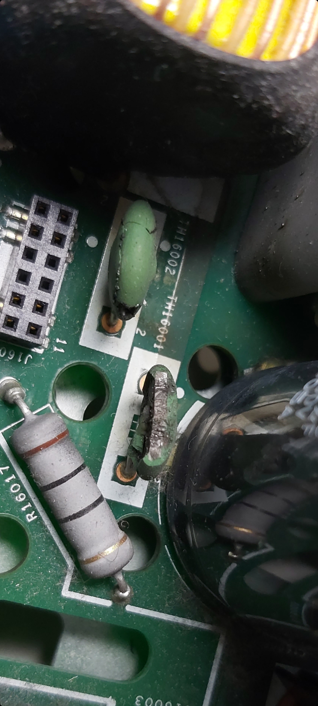
These two capacitors are defective. do you know the data for these?
TH16001 and TH16002.
Thank You
Max
Hi guys, I own a connect amp that was plugged (by previous owner) in to 220v when switch was on 110 v.
I replaced the fuse, replaced the TVR14241 (mov) and i noticed that the TH16001 also cracked. I could not source the Sck054 needed to replace this part in my local electronics store, so I hardwired it for now, and everything works perfectly.
Questions are:
- with normal use (no power surge, no wrong voltage), will the unit get damaged if I keep it like that?
- is th16001 used in 220v setup, or is it for 110v only, and th16002 for 220v?
If it will Increase the lifespan of the unit, i will order the SCk054 online.
Thanks for this super interesting group discussion, got me already quite far!
I have noticed that the 4 diodes (marked with black stripe) do not give any Reading on my multimeter.
Gruv2ths, sorry one more question. Do you have the winding diagram for the transformer PQ3230 in the 36V section? I think mine is dead (would explain the broken Schottky diodes). On the primary side I only find one good winding whereas there are 3 pins with wires attached. On the secondary side no connectivity between the thick wires which run into the pcb. Will be tough to find a replacement...maybe need to take it apart and wind a new transformer myself. Thanks!
Hi Gruv2ths,
I tried both your riser card and mine with no change in the noise level issue. The noise exists whether the analog inputs are used or the source is digital streaming. I posted a video in YouTube. Hopefully you can access it at:
https://www.youtube.com/watch?v=l2rIuxriv_s
I'd like to get my hands on another logic board (i.e. the top board) to see if that would eliminate the noise.
Thanks Tim. When I tried the other logic board, I didn't swap the riser board! will have to try that, wasn't aware of any control circuitry there.
I'm leaning towards the amp chips, but would really like to know if they were shorted would the problem present itself as it is?
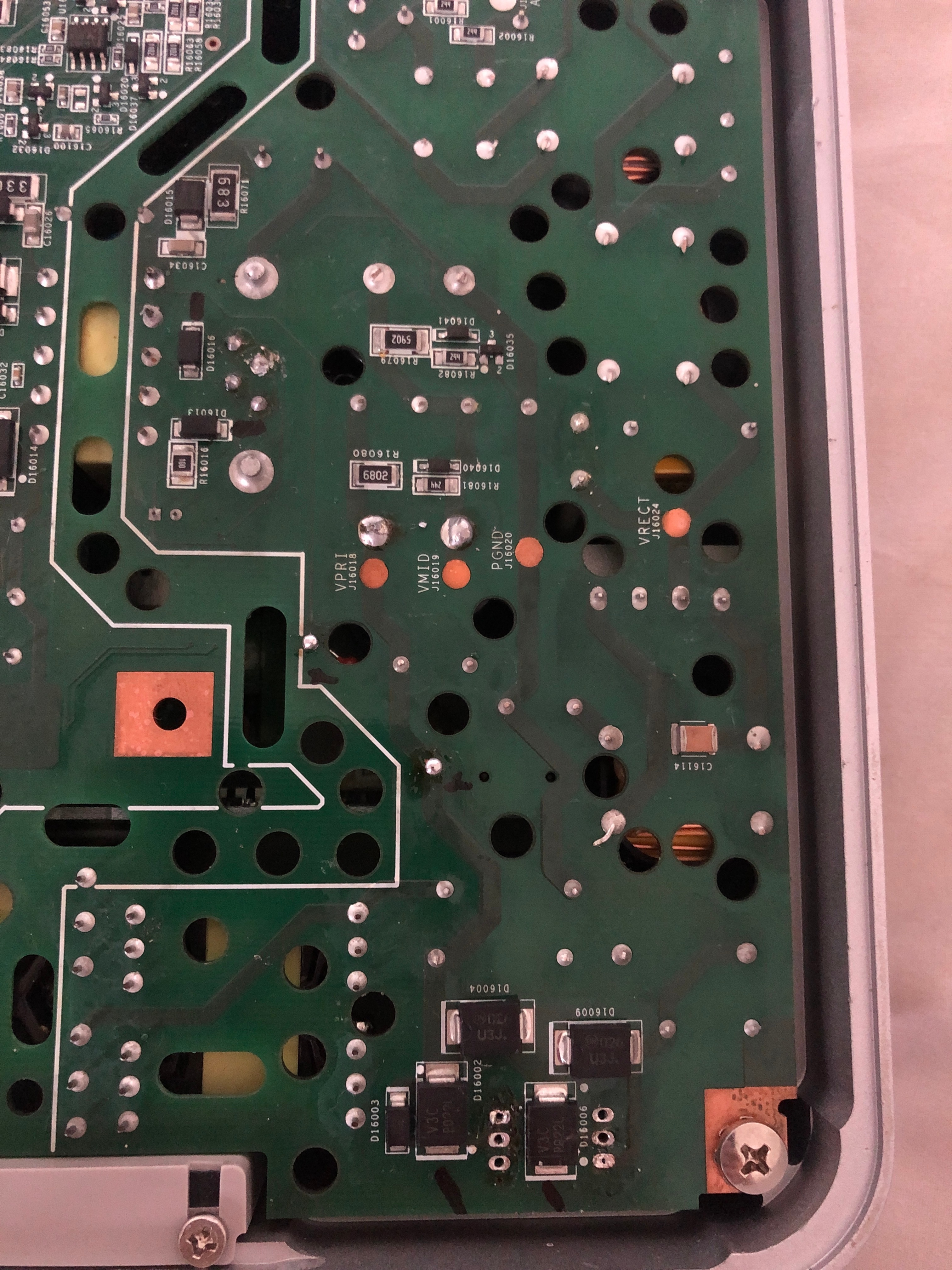
Should the 36V be available anywhere on the board while in standby?
If I remove the amp chips should the 36v present itself once the volume is turned up?
This photo is from 2 years ago from this thread from a user that I don't think got to the bottom of his issue. The hilighted area as I understand is the 36v supply?
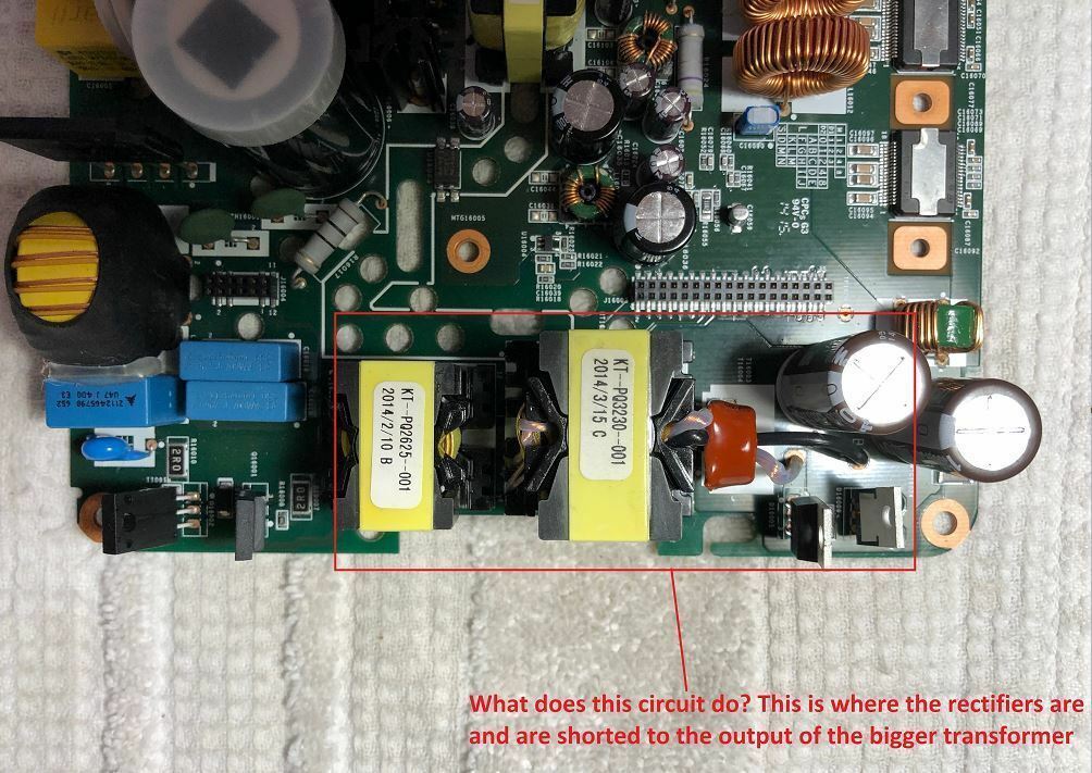
Pietje Puk - Let me make some measurements on a 36V converter transformer that have here. The continuity should be the same on mine as yours, different turns ratio though I think? (given the lower mains voltage here). If it's the transformer, all is not lost. With the bias converter transformer, when they go open usually once removed you can see where the winding burnt off the termination pin. Fingers crossed that if your transformer has blown open that it can be repaired the same way.
Piperdog - Thanks for the youtube, that helps. Very weird! Wondering if you had a power surge, if maybe some of that over voltage made it through the bias power converter and up to your logic card. If you have a microscope, can you look for cracked ceramic capacitors? I suspect noise that should have been damped is getting in and causing that weirdness.
Pietje, he is using a known good power board so hopefully the Class D stuff is ok.
Pietje, here is what I measured.
Let me know if it’s confusing
Let me know if it’s confusing
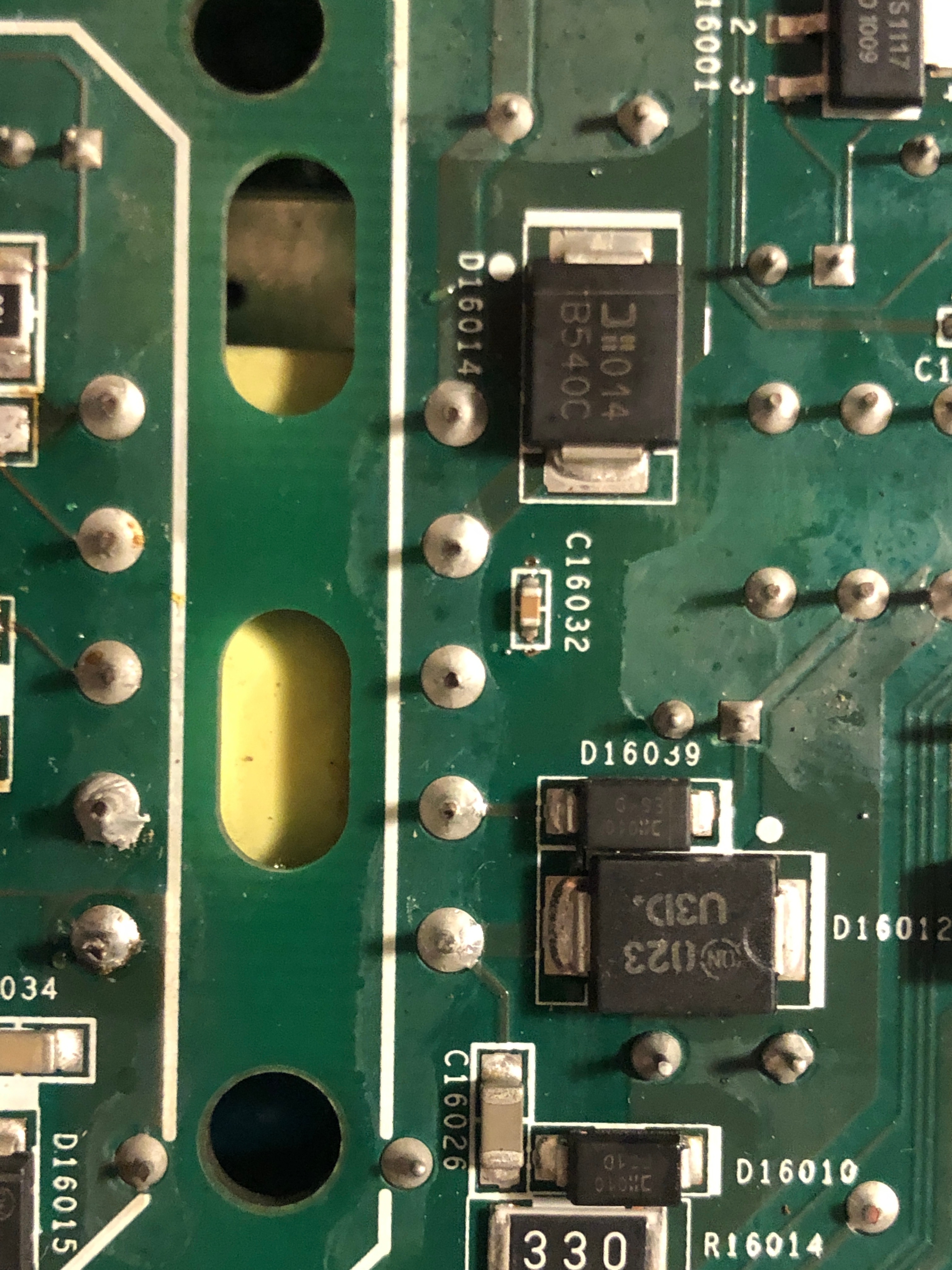
Update: removed almost all diodes from underside op primary side. Theyre all Good. Something I noticed is that all the 5 points of this winding in the secondary side are shorted together, is this right?
Gruv2ths thanks. I get the same so transformer should be fine then. Need to peel back the onion a bit more. Parts have arrived so will start replacing the diodes and capacitors. Also managed to fix one of the Play5 (1st) gen which I bought recently. Just had to replacw the 10 Ohm resistor in the power supply on the primary side.
I am still puzzled as to why your shorted diodes don't blow the fuse. Wonder if the common core inductor just before the diodes has been blown open?
Good news on your Play5, never tried to fix one. I have a Play3 that shuts down after a few minutes. That I will save for another day.
Good news on your Play5, never tried to fix one. I have a Play3 that shuts down after a few minutes. That I will save for another day.
Gruv2ths,
I couldn't detect visually any cracks in the solder joints of caps on the logic board. I don't have the oscilloscope or skill to troubleshoot the noise I'm hearing. I'm an old analog guy and digital control circuits are new to me. I'll wait until I can locate another logic board to try as a replacement. If you or anyone else on the forum has a logic board they want to sell then please let me know.
I couldn't detect visually any cracks in the solder joints of caps on the logic board. I don't have the oscilloscope or skill to troubleshoot the noise I'm hearing. I'm an old analog guy and digital control circuits are new to me. I'll wait until I can locate another logic board to try as a replacement. If you or anyone else on the forum has a logic board they want to sell then please let me know.
Pdog,
What I meant was, look for cracked ceramic caps.
I have a spare logic board.
Will message you.
What I meant was, look for cracked ceramic caps.
I have a spare logic board.
Will message you.
Pdog,
You can take a radial leaded ceramic cap and touch its leads to the various ceramic cap leads while the noise is obvious and see if any of them seem to like the parallel capacitance and the noise is damped. Just a thought.
You can take a radial leaded ceramic cap and touch its leads to the various ceramic cap leads while the noise is obvious and see if any of them seem to like the parallel capacitance and the noise is damped. Just a thought.
Page 6 / 17
Reply
Enter your username or e-mail address. We'll send you an e-mail with instructions to reset your password.