The amp has no power. Is there an internal fuse for this unit?
Has anyone taken one apart?

Page 7 / 17
Userlevel 2
Hello gruve2ths excellent jobb back there.
I have a zp120 it goes flashing orange and white when play is pressed. I have changed the driver IC 14pin on the logic card and that broblem was solved internet connection and volume ok but still not get any sound from the speakers!! I'm not sure that i soldered all the pins from the new 14 pin IC on the logic board .... is there any chematic or can i measure it some way.
I have a zp120 it goes flashing orange and white when play is pressed. I have changed the driver IC 14pin on the logic card and that broblem was solved internet connection and volume ok but still not get any sound from the speakers!! I'm not sure that i soldered all the pins from the new 14 pin IC on the logic board .... is there any chematic or can i measure it some way.
Userlevel 2
This guide might help although it is for the ZP100.
http://www.mediafire.com/download/0duavcuf1zyuc8u/sonos_dismantle.pdf
http://www.mediafire.com/download/0duavcuf1zyuc8u/sonos_dismantle.pdf
Userlevel 2
I bought a used Z120 with an unidentified power issue. It was dead.
The 5A fuse is open. No other components show visible damage. When I shorted out the fuse to see if the amp would power up there was a momentary flash of light near the centre of the power board. I say momentary because I quickly opened up the fuse again.
It appears to me as if something arced or there is a short somewhere downstream of the fuse. Everything I measure with an ohm meter seems to react ok. The varistors near the large filtering caps are not shorted. Before I try to replicate the action of shorting the fuse again to see what is arcing I thought I'd see if anyone had any ideas as to the fault.
Also, has anyone created a schematic of the power supply?
Hi Gruv2ths.
After i´m push play its still 15V at 36V testpoint?
After i´m push play its still 15V at 36V testpoint?
piperdog,
A flash of light usually indicates something has died -- in a hurry -- usually letting out its smoke. Of course, everyone knows that smoke is required for proper operation and after the smoke leaks out, operation ceases. Further, the flash of light (former) device is usually the victim of another issue.
Some units will blow fuses for no good reason other than the fuse was probably poorly specified and fatigues over time, eventually failing. I don't have enough data to know if ZP120 is one of these units or not.
I can't recommend the strategy of inserting a fuse eliminator as an expedient. Unless I know that a given (dead) unit is subject to nuisance fuse failures, I'll track down the root cause of the failure before applying power to a unit. Powering a (dead) unit prior to repairing the root cause typically expands the failure, fuse or not. Also, even if they appear to be OK, replace any components in the current path of the root failure because these components were probably stressed during the original failure and you will likely be faced with another similar failure as these stressed components fail in the future.
Inspect the board using a magnifying glass. There is almost always some sort of visual physical clue indicating which component gave out its smoke. Of course, with our modern, ever shrinking components, these physical clues can be small too. Sometimes the only clue is a small black dot on the non visible side of a surface mount component.
Hi Gruv2ths,
I had some fun trying to bridge a 0.1ufd cap across some of the caps on the logic board. It's not a practical thing to do on the small package caps but the principal of the problem-solving action is sound give the noise I'm hearing. Unfortunately my efforts had no impact. I don't think it is cap filtering issue. What I did discover, however, was when I disconnected the three amp antennas from the logic board, and therefore shut down the Sonos net, the noise almost entirely disappeared. The amp was hardwired by Ethernet cable to my music server and the amp had been broadcasting to the other Sonos units. I could still hear the noise faintly but not enough to make the amp unusable which was the case before. Unfortunately I don't want to use the amp as a stand alone amplifier unconnected to a net. I then tried connecting the amp by another Ethernet cable to a Sonos bridge. The Sonos net went into action, but the noise returned which I didn't expect. I thought the Ethernet would just be an in and out connection through the amp with no impact on the noise. In any case, it appears that the issue is in the logic board and not as simple as a damaged cap.
I'm not sure whether I want to sink any more money into the amp at this point.
Another thought, since the bridge was sitting near the amp maybe that wasn't a "fair" set-up. Even with the amp's antennas disconnected, maybe the amps logic board was picking up enough wi-fi signal from the bridge to start processing the Wi-fi signal and triggering the noise issue. I've packed everything up now. Maybe tomorrow I'll try again with the amp much further away from the bridge. However, even if the logic baord stops processing a Wi-Fi signal and the noise disappears (just a theory), it still leaves me needing a new logic board.
It's all fun though!
It's all fun though!

sotisg69
Hmmm, well that's not good. The 36V is what biases the output section.
So we need the 36V.
Can you check to make sure the CPU GND test point is 0 ohms to the RTN36V test point. If not they need to be shorted together.
The controller for the 36V and the 36V gate drive circuit is on the riser card between the power and logic boards. Near the transformer on the riser board. (the transformer is part of the gate drive for he 36V supply)
That is as good a place as any to start.
Let me look at one I have and will see if I can make a test aid.
Userlevel 2
Lacking a schematic to do proper trouble shooting I slowly applied power to force evidence of a fault without hopefully doing damage. One of the varisters eventually exploded. I desoldered its remains. Although I had measured it as open it was evidently damaged and shorted out under power. I reassembled the unit but still don't have power so I'll look for another faulty component on the power board. At least now I can apply full power without any shorting occurring.
Pdog,
Wow this is a new one for me.
A few thoughts.
- I have noticed that when removing the antenna connectors from the wifi card it is exceedingly easy to mess up the termination given all the glue holding them in place.So you might want to try connecting the antennas one at a time and see if one of them makes the problem worse then the others. These things will work without all 3 antennas connected.
- Another thing you can try is to remove the wifi card all together and see what happens. Then just run it with the ethernet, for that test.
Userlevel 2
Upon closer examination I see that a current limiting in-rush thermistor has over heated and cracked. Its a SCk054 (schematic TH16001) which I'll have to replace to progress further.
Good idea. I'll try removing the Wi-Fi card tomorrow and see what happens.
Gruv2ths, thanks for the quick reply.
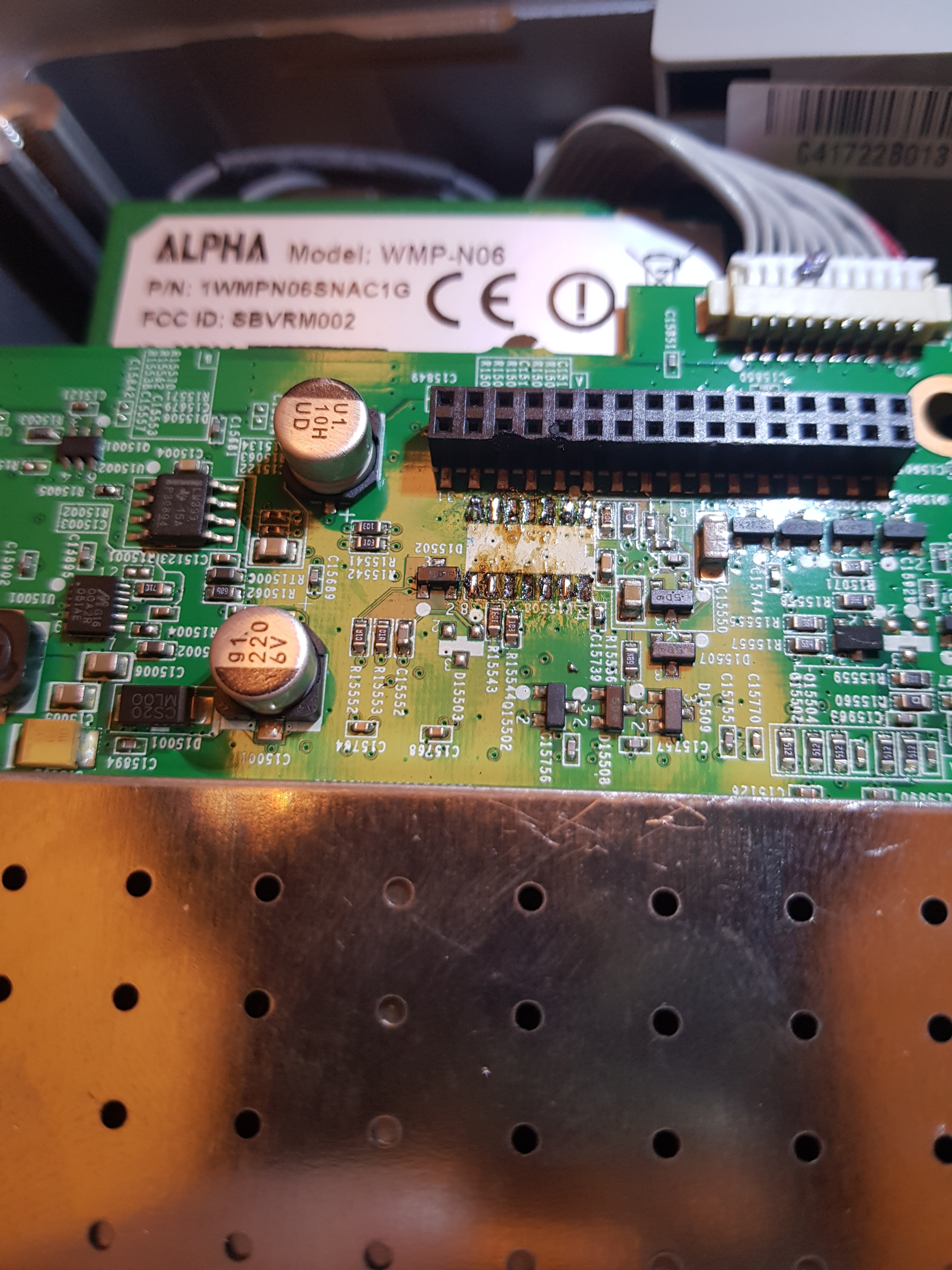
The CPU GND test point is 0 ohms (shorted) to the RTN36V test point but i notised that i dont have power after the transformer on secondary side See picture attachedthe
The CPU GND test point is 0 ohms (shorted) to the RTN36V test point but i notised that i dont have power after the transformer on secondary side See picture attachedthe


You could have sent it in for replacement for a modest cost. I sent back a ZP100 for around $150. SONOS sent me back a brand new ZP120.
Gruv2ths,
Bingo! It's the Wi-Fi card. With it removed the "static-like" noise is gone - even with a Sonos bridge (radiating RF) sitting next to the amp.
The Wi-Fi card is tricky to remove from the logic board. There is a mechanical clip on each side of the card and glue has to be removed to free it. There is also a small square foam pad glued between the Wi-Fi board and the logic board to secure the Wi-Fi card even more securely. I mention that should anyone else try to remove the Wi-fi card from the logic board.
The amp is connected to my music server by Ethernet cable and there is a pass through Ethernet connection to my bridge which then creates a Sonos net with my other units. As long as my amp doesn't need W-fi, I'm ok. Everything sounds and works fine. BTW, without the Wi-Fi card in the amp, the front controls on the amp are disabled. Fortunately a remote controller will still perform those functions.
Userlevel 2
I didn't realize that it would be that inexpensive for Sonos to repair an out of warranty unit. Thanks for the info. Unfortunately they may not touch my unit now that I've opened it up. At any rate, I received replacement fuses, varistors and thermistors today from Digikey. If things work out I'll post the Digikey part numbers. Now I have to find time to install them. Hopefully they are all that is required but of course there is a reasonable chance that something else is wrong with the power supply causing these parts to fail. I'll know soon.
Pdog,
Glad you got down to root cause.
Didn't know about the wifi card disabling the front button panel.
Thanks for the heads up on that.
Glad you got down to root cause.
Didn't know about the wifi card disabling the front button panel.
Thanks for the heads up on that.
sotisg69,
FYI-You won't see a voltage on the transformer secondaries unless you are in AC mode with a tru-RMS meter.
And the DC measurements need to be made with the black lead of your meter to either RTN36 or CPU_GND (they are shorted together as you mentioned)
A few observations, if your AMP shows up on your phone then you must have 3.3V, 8V(5V after the liner reg) and 15V. You most likely have your meter referenced to the wrong point.
Another though is that the logic card probably turns on the 36V supply through the driver chip that you replaced. So if you're not sure the solder is correct on that chip, i would concentrate there. Can you take a high res pic of the chip on the board for us to take a look at? We may be able to inspect your solder if the pic is clear enough.
Userlevel 2
I decided to skip the dim bulb tester although I'll keep it in mind for the future. I replaced the 2 thermistors, 2 varistors and 5A fuse in the power supply section and applied power. The good news is nothing shorted out. The bad news is that some component must be open downstream because I'm not getting voltages where I should. I wish I had a schematic. It would be so easy now to trouble shoot with it. Or another good unit to compare voltages.

Wow -- that’s excellent to hear.

Piperdog, Any chance you've got any updates? I'm in the same situation.
Gruv2ths thanks for the suggestions you got a point there. This pickture was taken before i soldered the new chip
I don't have any updates. I put my repair on hold until I can find someone who has had more time than me and who has created a schematic of at least the power supply section. Alternatively I'm keeping my eyes open for an inexpensive used ZP120 so that I can use it as a reference for the correct voltages and therefore to trouble shoot my nonworking unit..
sotisg69
Oh my! Well that's not good.
What I would do is take some isopropyl alcohol with an acid brush and clean away the flux and see what is left. Also Tin the pads that are left once clean.
I will take a pick if a good board. Give me a little time.
Oh my! Well that's not good.
What I would do is take some isopropyl alcohol with an acid brush and clean away the flux and see what is left. Also Tin the pads that are left once clean.
I will take a pick if a good board. Give me a little time.
Page 7 / 17
Reply
Enter your username or e-mail address. We'll send you an e-mail with instructions to reset your password.