The amp has no power. Is there an internal fuse for this unit?
Has anyone taken one apart?
Page 4 / 17
Hello.
I have almost the same problem as runecal. i have 6 amps that have gotten overvoltage. i have changed the 2 large caps. and a little thermistor and the fuse.
i bootes up and is connected to network, but when i tries to play music, it turns to blinking orange.
any idea???
I have almost the same problem as runecal. i have 6 amps that have gotten overvoltage. i have changed the 2 large caps. and a little thermistor and the fuse.
i bootes up and is connected to network, but when i tries to play music, it turns to blinking orange.
any idea???
Couple of observations.
-if you are getting the 3.3,8ish,15 on the secondary then the bias converter PWM is working correctly.
-The reason you are seeing 0V on the transformers pins is because you are looking at AC with your meter set to DC. Those biases measured in the logic card say to me that the bias converter is running and the output is making its way to the logic card. Good sign
-I can only think of one thing left to do, and that is measure the output of the buck converter on the bottom of the logic card. There is a inductor with a (normally) yellow electrolytic cap. Solder a wire to the striped side of the cap and put the card back in and plug in. You can put the red lead on the wire and the black one to chassis. Should have 1.5V output.
Do you know much about reading serial (UART) from a computer? You may have noticed a 4 pin header under the EMI shield that you removed. There may be some diagnostic clues coming out of that serial headder.
The one I am working currently has a confirmed good power and riser boards and shows up in the Sonos app but when you push play I get orange and white blinking leds. Wanting to read that header and see if it can give me a clue as to why mine shizes the bed when I push play.
i have 4 amps, that goes flashing orange and white when play is pressed. have you got any luck on that issue???

Wow, really nice work!
Blinking orange and white is fault mode. The Amp is either too hot, or there is a short. Make sure there is adequate ventilation and check that the wiring is not frayed or sticking out, causing a short.

readings at the pins. I thought I could not test this because when I power on the device it blows up. I
I have an educated guess about what is wrong with your device. If you replaced the PWM and it still doesn’t work, then I’d check the two mosfet devices identified in these images. Look for a short between the various pairs of pins (you should not find any 0V drops if you test the 6 combinations with a diode tester). If you don’t have a diode tester, you can just remove the 2 components and see if the device boots up.
These devices are part of the circuit that is used to generate 36V power that is used to drive the amplifier. It is only active when the device is actually playing music. An otherwise working device will boot up without them, and will even play at very low volume. After booting up without the 36V present, you won’t be able to turn up the volume, and the device will start flashing amber. This isn’t permanent and it will go away once you replace the mosfets.
When the time comes, be aware that the silver clip on the top can be a pain to replace. It can be bent open with two sets of pliers so that it is just a bit narrower than the diodes it covers. That will let it do its job and it will be much easier to replace.

Toden,
The flashing orange on mine was due to a bad driver IC on the logic card. It is a 14 or so pin IC.
Mine would flash orange and white when i push play, the app keeps playing like nothing is wrong yet no sound from the amp.
The flashing orange on mine was due to a bad driver IC on the logic card. It is a 14 or so pin IC.
Mine would flash orange and white when i push play, the app keeps playing like nothing is wrong yet no sound from the amp.
I have for sale, 3 Connect:Amp power boards with chassis and bottoms (wifi antennas and white plastic pan) that are tested with a known good logic board. I can send you videos of them working with a pair of JBL towers.
You just drop in your logic card and your in business.
Message me at gruv2ths@gmsil.com if your interested.
You just drop in your logic card and your in business.
Message me at gruv2ths@gmsil.com if your interested.
I hope someone in this thread can help me as it’s been a while since this thread was created. I have a ZP120 from a friend of mine. I opened it up and immediately saw the blue 10 ohm 2W resistor was blown near the pwm (I think it’s called) with the black heatsink attached to it. I replaced both of these components as I thought the resistor had blown due to the pwm being bad. After replacing these components, the resistor blew again after 30 seconds or so. Anyone has an idea on where the short could be? I also removed the clips of the transistors and the diodes to their heatsinks and those show a small sign of black burn marks.
I’ve fixed a lot of the zp120, but this is one that I don’t know of a definitive fix for, and I haven’t been 100% successful trying to fix it. 90% of the time, when there is a blown 10ohm resistor, just replacing it gets the device working again. Similarly, replacing a bad PWM usually does the trick.
You should look at info earlier in this thread (or just google it) for how to build a dim bulb tester. This has a huge advantage in this kind of case. On a broken device, the bulb will glow brightly, but it won’t dim back as it should (once the power supply capacitors are charged). It serves to limit current, and will prevent more components from failing every time you test something. Without this, you may end up replacing the 10 ohm and pwm multiple times.
You can check the PWM device by testing each pair of pins using a diode tester (test in both directions). You should get either infinite or ~ 0.6V between pins. If you get a 0V reading between two pins, your PWM is bad again.
If you remove the PWM, try powering up the device without it. If it doesn’t draw a ton of current (ie: the dim bulb goes out), then that confirms that the problem is ‘downstream’ of the PWM.
Check the transformer. There are 5 pins on each of the primary and secondary sides. They are organized as one group of 3 with a centre tap, and a separate (isolated) group of 2. That makes 4 separate windings on the same core. You should get low resistance across each coil within each winding, but no continuity between any two different coils. If you find continuity between two different coils, then you have a short (hope that makes sense). Also, with a good multimeter, you should find 0.1 or 0.2 ohms when measuring a coil. If you get 0 ohms, then you may have a short within a coil.
Here is a less likely bit that you can check which is easy to check… There are 4 largeish surface mount diodes near one of the corners of the board on the underside (across from the power input). Check these 4 to see if any have failed using a diode tester. (You can do it in circuit) I don’t think it would cause your issue, but these do go fairly often in my experience.
gruv2ths,
do you have more info about that ic, model, pictures, where to buy
do you have more info about that ic, model, pictures, where to buy
Which IC?
you wrote about a bad driver ic on the logic board, you succesfully have replaced.
just to be sure, witch card is the logic board. the one with ethernet or the one rising from the powerboard
just to be sure, witch card is the logic board. the one with ethernet or the one rising from the powerboard
Ok thanks for your fast reply, I indeed looked at the posts before and saw the scheme of all the readings at the pins. I thought I could not test this because when I power on the device it blows up. I will build a dim light tester, check the transformer and the pwm again as well as the diodes. I have a very cheap multimeter with a diode function, is this trustworthy?
gruv2ths,
you wrote about a bad driver ic on the logic board, you succesfully have replaced.
just to be sure, witch card is the logic board. the one with ethernet or the one rising from the powerboard.
i have read this thread several times to figure out voltages and troubleshooting, and i think i got all the voltages right.
it sounds like i have the same problem you descibes.
it has been very interesting reading.
just need to get over the final bumb. i have to say i am noob at electronics. i am a electrician, so i hope i have a little understanding.
Hi All,
I wish all of you guys are doing OK. I am the one fixed the broken transformer about 1 year ago.
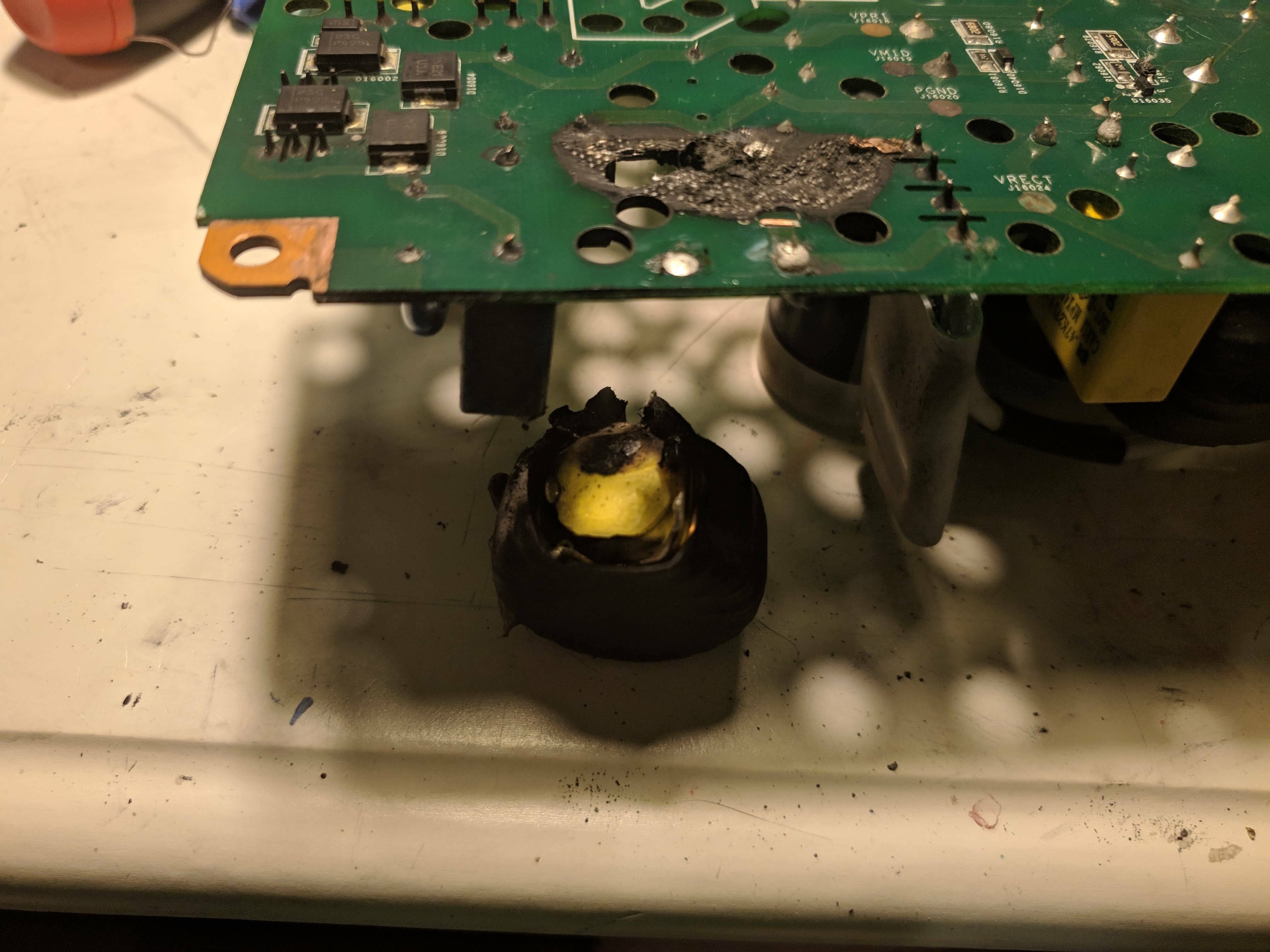
I figured I will try more repairs during this lockdown just for fun. I got one SONOS AMP off eBay with power up failure. After opening the AMP, I am shocked to see there is a black burn around the input rectifier. The inducter after is completed blown!
I managed to fix the inductor and now my Amp is back online in the SONOS AMP. Right after I start playing music, the LED turned from solid white to flashing white and amber! It indicates the AMP is bad.
I check all my voltages and everything is OK except the 36V stuck at 15V even after play starts. I think something is wrong for the 36V regulator. Any tip to diagnose that part of the circuit?
Thanks,
Benbendog

@gruv2ths Ahhh you finally fixed that! How did you determine that IC was bad? Thats a tough nut to find is bad!
 +1
+1
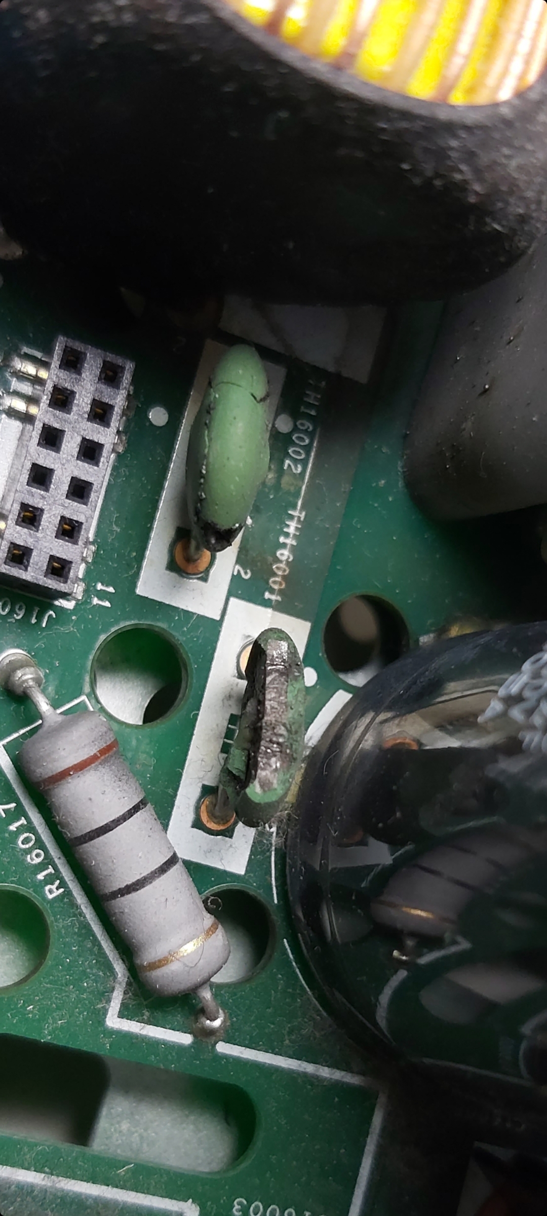
Hello, im from Germany and need your Help.
These two capacitors are defective. do you know the data for these?
TH16001 and TH16002.
Thank You
Max
Hi there, are these thermistors the same as they are in an playbar? In my playbar, the green thermistor are burned and I´m looking for the type.
From the 36 volt test point, you can try to trace backwards. There are two schottky diodes behind one of those nasty clips towards the back of the board from the 36v point. The 36 volt and ground pass through an inductor before they reach those diodes. Each 3 pin schottky diode package has two diodes and all four of the diodes are in parallel. Check the diodes. Note that the 36 volts does not come on until you press play, so you can't expect 36 volts all the time.
I have found problems here, as well as these short connector on the riser board. The input to the 36 volt supply passes up on that riser connector are is processed on the riser. There are 8 henpins on the connector but only four signals (they are in pairs for amperage I think). When 36v is needed, that circuit that will pass it down through the riser board back to the main board.
Hey old friend!
It was one Hail Mary after another.
I noticed that when it was failing the preamp chip was never being un-muted. I followed the mute line from the pre-amp chip up through the riser card to that driver chip on the logic card. I pulled the datasheet and found that that pin was an output and its output was stuck at 100 ohms or something like that. The other outputs on that chip were fairly high resistance. Learned a lot, many months of four letter words though. Lol
Hi guys,
Im in need of help with my zp120 ive been following this forum, built a dim bulb tester, found a short replaced the bridge rectifier and fuse, also found a small burn mark under the tranformer one of the copper wires came off so soldered it back into place, still no power, im getting no voltage on the secondary side.
Im in need of help with my zp120 ive been following this forum, built a dim bulb tester, found a short replaced the bridge rectifier and fuse, also found a small burn mark under the tranformer one of the copper wires came off so soldered it back into place, still no power, im getting no voltage on the secondary side.
Sounds like you have a open winding. Take off the transformer, you will probably see a burn mark where it came open.
Also do you see 300ish volts on one pin of the transformer and neutral on another, both on the primary side?
There is also a 100 or 10 ohm 2W-ish axel leaded resistor in series with the primary, make sure that is not open.
There is also a 100 or 10 ohm 2W-ish axel leaded resistor in series with the primary, make sure that is not open.
I’m in the same boat as most of you (though I haven’t opened up my unit to see what’s going on - I wouldn’t know how to fix it anyway). My unit refuses to power on, and it happened I’m sure “coincidentally” right after I updated my app.
Here’s what it looks like to me: Sonos may have done away with their “recycle” program, but now they’re using “forced obsolescence”, and shutting down older units to force people into upgrading.
My unit - a ZP120 - had been used so infrequently that it should have lasted 40 years. And now, all of the sudden, and right as I updated my app, it goes bad for no reason? And Sonos is telling me that I can’t get another ZP-120 and I have to get one of the newer models.
That’s some sketchy business practices right there.
I have a ZP100 that I think took a power surge, perhaps through the RJ45 port. After that event, the unit would power up, the white light would flash forever & there was no network activity on any of the RJ45 ports.
I recently had another ZP100 go out, so I took the CPU board from that device and swapped it into the first one. I powered it up, RJ45 ports work, it gets an IP and shows up on the Sonos app (as the “donor” ZP, naturally). However, when I go to stream anything (local music or through a service) it tries for a while & then I get a message like “Can’t play this station” from the app. Is there something else I need to do on the player to get it to stream properly?
Hi,
Ive removed the tranformer with great difficulty one of the copper pads lifted but should be ok, I also changed the resistor aswell, the only thing im uncertain of where it is burnt I cant find the trace for where that pin connects to on the board(directly above D16016) I cant see any trace or cant find hear any beep to which component its in series with.
Ive removed the tranformer with great difficulty one of the copper pads lifted but should be ok, I also changed the resistor aswell, the only thing im uncertain of where it is burnt I cant find the trace for where that pin connects to on the board(directly above D16016) I cant see any trace or cant find hear any beep to which component its in series with.
Page 4 / 17
Reply
Enter your E-mail address. We'll send you an e-mail with instructions to reset your password.