The amp has no power. Is there an internal fuse for this unit?
Has anyone taken one apart?

Page 2 / 17

Thanks Tim. When I tried the other logic board, I didn't swap the riser board! will have to try that, wasn't aware of any control circuitry there.
I'm leaning towards the amp chips, but would really like to know if they were shorted would the problem present itself as it is?
Should the 36V be available anywhere on the board while in standby?
If I remove the amp chips should the 36v present itself once the volume is turned up?
This photo is from 2 years ago from this thread from a user that I don't think got to the bottom of his issue. The hilighted area as I understand is the 36v supply?
It’s hard to know what symptoms a blown chip would cause. I once had blown amp chips that went in such a way that they lost some of their pins in the process -- literally blown off. In something like that, the traces could be damaged, it could cause shorts elsewhere… It’s just too hard to know for sure what to expect.
That section is the 36v supply. If you are familiar with the primary side voltages, the power path from input 120/240v is rectified and passed through a dual inductor and 320v dc is produced which is available on pin 5 of the primary side of the tarnsformer. Somewhere around the mosfets that are part of the doubling circuit that generates 320v, the circuit apparently branches and feeds into the 36v supply section you identified (I’ve never looked at where this happens in the zp120).
I just looked at that section on a board… it does look fairly straightforward. What I mean by that is that it should be possible to check many of the components. Bad diodes, capacitors or even open windings can all be looked for in circuit. The 3 pin devices that look like transistors are actually dual diodes and those diodes can be checked too (use diode test between the middle leg and each of the outer ones).
I have some zp120 devices that have the same symptoms you describe -- i just haven’t invested time in looking much further at this point. I have fixed a lot of the older zp100 devices, and they had similar voltages. In those, the 36v would be unavailable when in standby and i think the zp120 would be the same.
Please post back here is you find anything (good or bad).
piperdog,
Be sure to purchase at least two of these thermistors because the first will likely blow again as soon a you apply power. I suggest that you track down the root cause before applying power again. This is not a hard as it seems, just follow the current that blew up the original thermistor. This will lead you to a really sick component. Be sure to replace everything in that current path.
Also, I am leery about running up the power voltage as a strategy to troubleshoot switch mode power supplies. When the voltage is much lower than expected, the switch mode stuff will really try hard to maintain the specified output. This could imply much more current than average use cases.
If you have lab power supplies available, separate the ZP120 into modules, power them up and test them separately. The lab supply will have current limit capabilities to protect itself and the device under test from unreasonable current levels.
ITS THE DAMN RISER BOARD! I'm so happy, and at the same time mad at myself for not trying that when I tried a known good logic board.
with the repaired power supply, known good riser and existing (from the bad unit) logic board, I got my 36V and sound.
Now to dig and compare what's wrong with the riser board, or buy one of they're available.
Google Dim Bulb Tester for a simple, low cost way to protect devices that may still have issues...
I misled you. I forgot to reconnect the ribbon cable from the front panel controls! It attaches to the logic board directly below the Wi-Fi card. The controls now work fine. Your reply made me rethink what I had done. 🙂

So as promised above I have repaired my new ZP120, and another 120.
The first one:
Just the input bridge rectifier has a shorted diode that blew the fuse. Once the bridge was replaced it has worked fine.
Second one:
SOmetimes it came up no led, totally dead, other times it came up and would get 1/2 way through setup before crashing my network.
Noticed a primary side 350V 33uF electrolytic cap was toast. Replaced It and nothing really changed.
This one was a real head scratcher. The blown cap belonged to what appeared to be power converter circuit that provides biases around the board. Noticed that the GND test point had no continuity to the outputs of the tapped winding. I probed a good working ZP120 and found that all of the outputs of the bias converter were grounded together. So I shorted the return of the tapped winding(8.5V and 15V outputs) to the return of the single winding (3.3V output). Was nervious to power it back up, so just in case i used the dim bulb and it worked great. Replaced the dimbulb with the fuse and I am in business.
I did a chart so my crappy memory will have some help next time i tange with a ZP100. See below.

I lifted the shield can and connected to the UART -- here is what I get.
So I don't forget the pins are vdd,rx,tx,gnd …
U-Boot 1.1.1(1-16-3-0.9), Build: 0.9
MPC8272 Reset Status: External Soft, External Hard
MPC8272 Clock Configuration
- Bus-to-Core Mult 3x, VCO Div 4, 60x Bus Freq 16-50 , Core Freq 50-150
- dfbrg 1, corecnf 0x10, busdf 3, cpmdf 1, plldf 0, pllmf 3
- vco_out 400000000, scc_clk 100000000, brg_clk 25000000
- cpu_clk 300000000, cpm_clk 200000000, bus_clk 100000000
- pci_clk 33333333
CPU: MPC8272 (HiP7 Rev 14, Mask unknown [immr=0x0d10,k=0x00e1]) at 300 MHz
Board: Sonos Wembley
DRAM: 32 MB
DRAM test
Test complete - 1 errors, error pattern 00400000
### ERROR ### Please RESET the board ###
Remind me what your Amp was doing, or how it was failing?
I use the hakko 851 -- it is one of their pricier ones. I have nothing to compare it to, because it is all I have ever used. My amp was the blinking white light. After debug I found that it was stuck in the bootloader due to the dram memory test failing.
On your first one getting the chassis apart is an adventure.
If there is no blinking lights, then you prob have a blown fuse and no bias converter.
Listen to m0untainman, he knows what he is talking about. Replace the blown fuse with a 110V light bulb.
Then go looking for trouble.
Have fun!
If there is no blinking lights, then you prob have a blown fuse and no bias converter.
Listen to m0untainman, he knows what he is talking about. Replace the blown fuse with a 110V light bulb.
Then go looking for trouble.
Have fun!

Thanks! I just got notice the unit shipped and will be here next week. This weekend I am going to build a dim bulb tester and am planning on following Daniel's blog on disassembling the AMP. I am pretty good with soldering and have already checked out some possible part replacements on eBay.
Edit: I just found a site with some pretty good directions on building the dim bulb tester: http://www.geek-tips.com/2015/11/22/dim-bulb-tester/
Edit: I just found a site with some pretty good directions on building the dim bulb tester: http://www.geek-tips.com/2015/11/22/dim-bulb-tester/
I just wanted to check in saying that the CONNECT:AMP arrived over the weekend and it is in good shape. As far as I can tell it has not been opened. I plugged it in and sure enough no lights. With the holidays coming, I am going to have limited time to work on this, but I am planning on building the dim bulb tester today or tomorrow and hope to have a first look at the amp this coming weekend. I will report back what I find.
I'm sorry, but I'm going to be stupid trying to find a suitable spare part.Can someone give me a link to a suitable spare part, e.g. at mouser or digikey?Many Thanks
Either of these will work (both are in stock as of now)
Mouser #: 527-RL4504-3.2859S54
Mouser # 954-5D2-10LD
There were some smart people posting in this thread. Hoping they are still around.
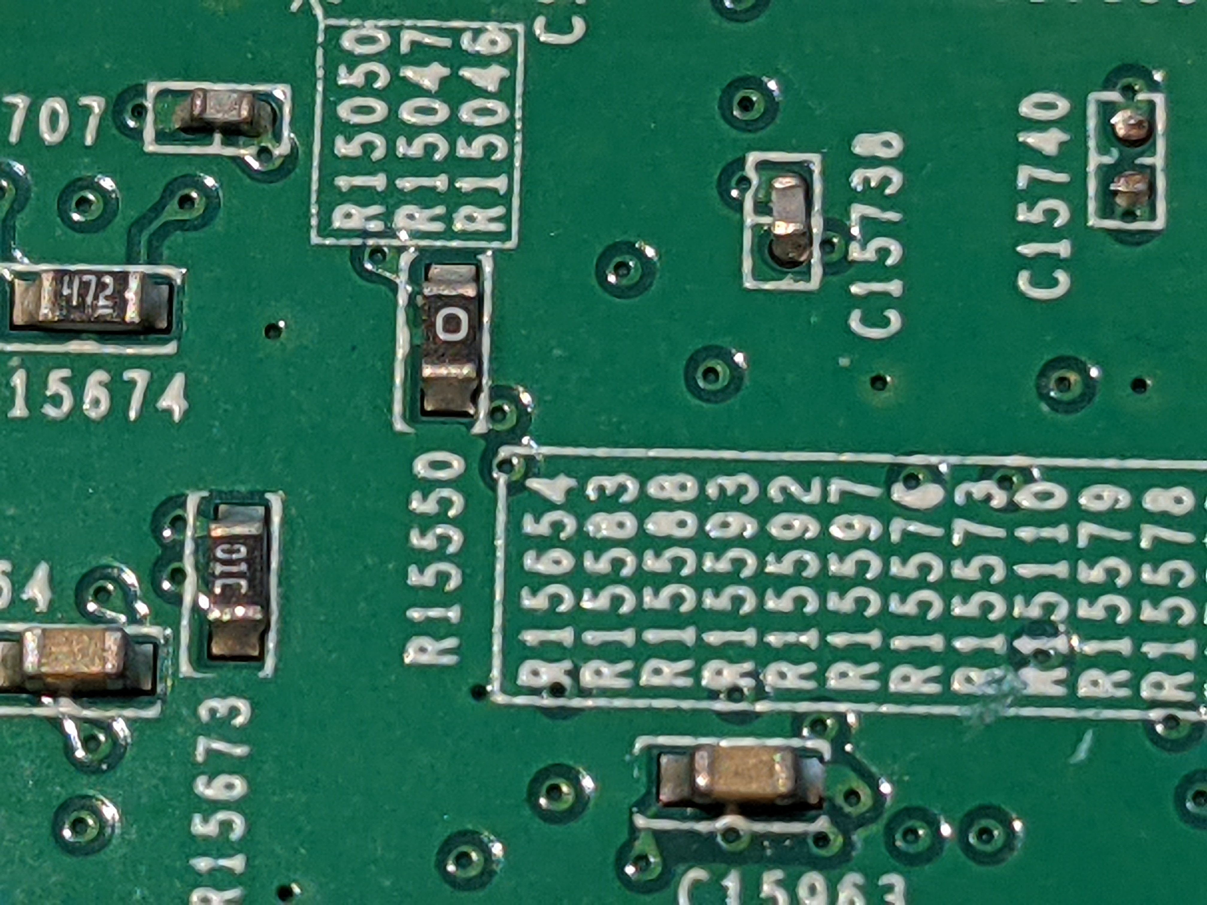
Hi, can anybody tell me the vale of resistor R15550, located under the WiFi module on the ZP120?
This component is missing on my board ( knocked off and lost by previous “repairer”). Oddly, the player still works, but I would like to replace it.
You’re in luck! That’s a 0 ohm jumper, so no parts search required...
TH16001 and TH16002.
Hi there, are these thermistors the same as they are in an playbar? In my playbar, the green thermistor are burned and I´m looking for the type.
SCK-054 or SCK-083 will work. These limit inrush current, and either of these does that (they have 5 and 8 ohms of initial resistance). The maximum amperage is 4A for the SCK-053, and 3A for SCK-083. Either of these is more than enough current for a playpar.
But sure… if you can find an SCK-053 (another manufacturer perhaps), then that would work. I think you want the first two digits >=5 and the last digit 3 or higher.
Great work!
So this is what I was hoping was not the culprit. But all is not lost if it is, I have replaced both of these on a repair once. I will tell you the easy way to get these off if need be. Found them on eBay from a stateside seller. Lots of the pins on the one side are supposed to be shorted together, but not all.. LOL
This I have found to be very very close to how Sonos has implemented the STA508.
http://www.st.com/resource/en/datasheet/sta508.pdf See Figure 7 on page 7.
m0untainman and I both have removed that same common mode choke, it separates the 36V power supply from the load.
So you can narrow down where your short is. We both had a rough time getting it back in. :-)
I would have given you the same advice that m0untainman did above, 'it probably aint the magnetics'!
Well guess what, I fixed one this weekend that had both of the windings of the common mode choke in the input filter (right after the diode bridge) blown open. Consequently the of the big storage caps threw up under it's top cap. Strangely there were no shorts and the fuse was not blown.
So what I do just requires a small flat screwdriver and your soldering iron.
All I do is solder all of the pins together on the side you want to remove. Then once there is a lot of solder across all of the pins keep moving your iron back and forth across all of the pins, the idea is to get all of the pins molten at the same time. Once you are liquid pretty much all the way across gently pry up the chip on the side with the solder. You will bend the leads on the side you have not touched. Then repeat on the other side.
FYI i lifted the pad from pin 18 on both the ones I replaced. But it is a no connect pin so no harm no foul.
That was it! I replaced the shorted diode with a 1n4148 as that's all I had on hand. No more orange light and she sings!
I have to thank everyone that participated in this thread, wouldn't have gotten her working without your help.
Congrats!
It looks like that component may be a zener with a working voltage of 2.1-2.3V (google philips bzx399). The 1n4148 is a switching diode, so it might behave a little differently. For example, the 36V section may be constantly ‘on’ rather than off during standby. If you get any more issues you may want to find a more similar part.
I had a quick look at my units that have been having similar issues, and sadly this part is fine on them.
Thanks for closing the loop on this.
Yeah I know I do get hung up on those secondary voltages ? I will say one last thing though about them however. I did check on both AC and DC and both are 0V.
The RTN points on the secondary are shorted at 0 OHMS and I did have the ribbon cable plugged in when I powered the amp on.
I also plugged in a network cable to the port and there is NO activity.
Also just for giggles, I replaced the PWM again to see if that would help but it made no difference.
The RTN points on the secondary are shorted at 0 OHMS and I did have the ribbon cable plugged in when I powered the amp on.
I also plugged in a network cable to the port and there is NO activity.
Also just for giggles, I replaced the PWM again to see if that would help but it made no difference.
There were two small spiders/bugs stuck inside the shielded compartment of the main board. They must have caused a small short preventing the amp form booting as all the voltages were there.
A very close visual inspection often saves many hours of troubleshooting.
Just checking in... ando1 - Congrats on finding the short 😉 The IC 😉 You made HUGE progress which is excellent. Looks like you are moving in the right direction! Don't give up!
Here’s a similar issue that your info helped me solve (I’m 99% sure)...
This is the same board that I posted an image of a couple of days ago. I had replaced some damaged components, and after that it would do the white/off/yellow/off cycle when I tried to play.
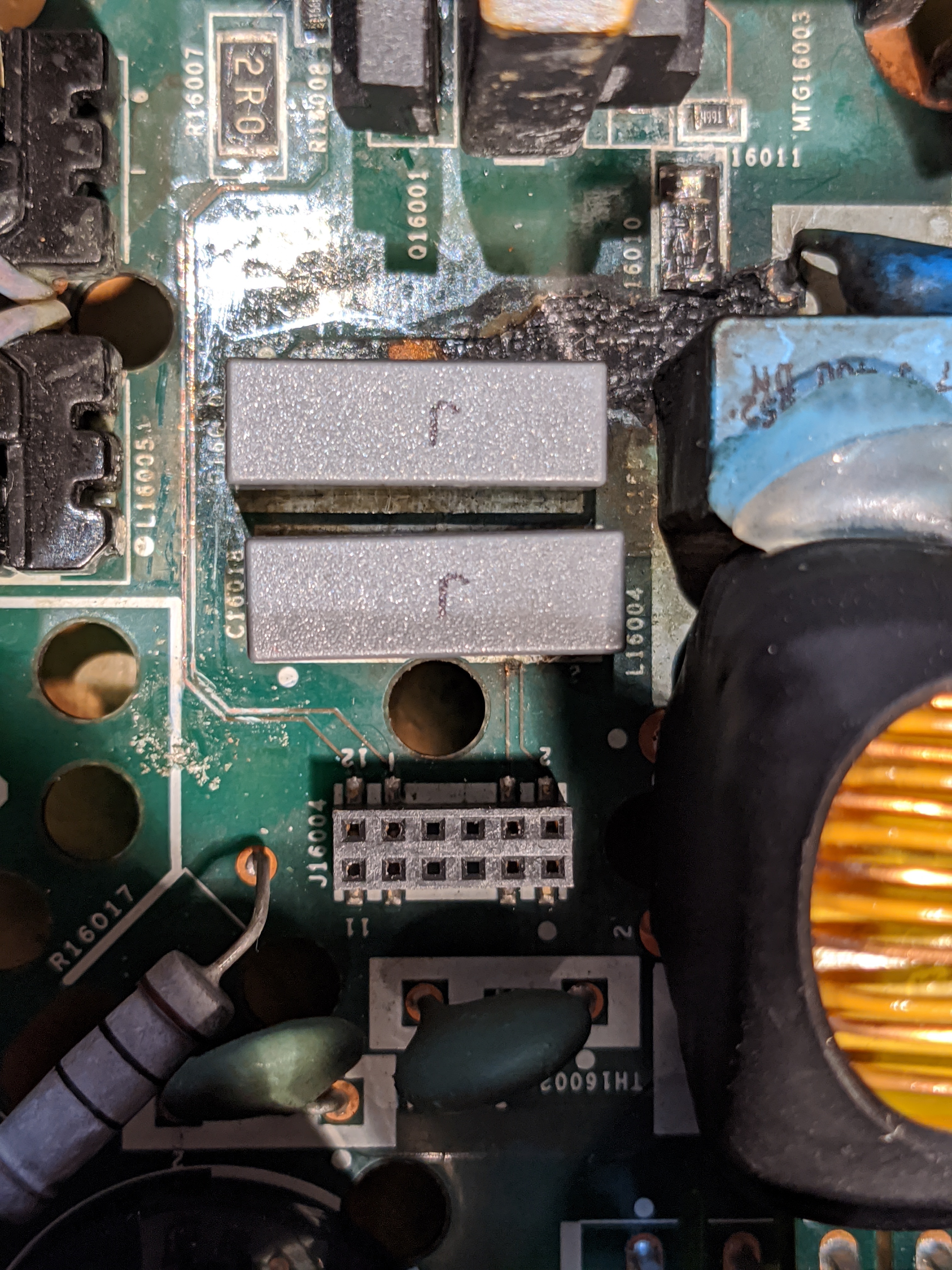
The 2 traces that run vertically between the transformer on the left and the two grey capacitors on the right connect two pins from the riser connector up to the MOSFETs above. They are damaged (confirmed with a continuity check) - it looks like the power surge the board suffered must have caused them to blow up.
I wouldn’t have found this so quickly without your success, shtnarg! I imagine I’ll have to replace that crispy looking R16010 on the top right as well -- it seems to be in the path back to the riser connector.
I'll check if the 36v turns back to 15v at standby. It's only temporary until I find the matching part..
Have you tried yours with a known working riser board and logic board? I'd like to still know more about the orange light error. Seems with all voltages correct the orange light refers to the riser/logic board or amp chips.
I have a Gen 2 Play 5 that has a short on the power supply. Doesn't seem to be much info out there on them.
Yes I have seen the 36V fall back. It doesn’t happen immediately but it does eventually.
My issue is on the power/amp board - see my other recent post.
I have a few gen1 play:5s but no gen2. The gen1 play5s are actually pretty horrible to try to fix. There is a massive buildup of heat in them when they are in use, and it causes a variety of different failures. The enclosure is basically a box with only one small bass reflex opening -- not great for air circulation.
Well, no joy - but oh so close…
It booted up ok, but when I hit play I still get the white/orange cycle.
I’ll keep looking but honestly I’ve been through this one pretty thoroughly so don’t know what to look for any more.
Actually… I feel so dumb… I still had my dim bulb in the circuit. Once I removed it everything worked beautifully!
I fixed all four zp120s that I described 10 days ago: https://en.community.sonos.com/advanced-setups-229000/repair-zp120-17442?postid=16419707 .
This included one with multiple rusted traces, another with a rusted transformer winding, one with two bad schottkys, and one with a bad PWM. There was other collateral damage too (diodes, caps, etc) but those were the dominant issues on each.
I also tried fixing a wifi/logic card, but was unsuccessful. I had one card that showed a dead short, and another that had a bad NAND chip. I moved the NAND chip from the card with the short to the other card, but it wasn’t recognized. It turned out that the good chip was ‘legacy’ and was a 64MB chip while the other NAND that it was replacing was ‘modern’ and was 128MB. It gave a message of ‘no NAND found’ in the UART, so I’m pretty sure it just doesn’t recognize the chip.
Page 2 / 17
Reply
Enter your username or e-mail address. We'll send you an e-mail with instructions to reset your password.