The amp has no power. Is there an internal fuse for this unit?
Has anyone taken one apart?

Page 5 / 17
Hi!
I just bought 2 broken Sonos amps, one is completely dead and is waiting for me to disassemble it but before I do that I need some help with the 2nd one.
When plugging in the power cord I can see a white light from the led then it goes off.
the previous owner explained what happened before it died:
“It was late one Friday evening and suddenly I only heard sound from one of the channels (mono) and I tried to remove the speaker cables by turning the knobs, and that didn’t work so I tried even harder and then the amp died. Should I mention that I was a bit drunk? I realize now that you should pull the connectors. “
any clues? I have disassembled it and didn’t see and fried components.

D16016 Cathode connects on a inner layer to the junction between C16034 and D16015. Just ohm it out, its prob fine.
That is the primary side snubber. I would also check to make sure all 3 of the diodes in that area are all ok. I have had shorts there.
Did you find something blown open on the transformer? That mark on the top side suggests an open where the pin meets the magnetic wire.
That is the primary side snubber. I would also check to make sure all 3 of the diodes in that area are all ok. I have had shorts there.
Did you find something blown open on the transformer? That mark on the top side suggests an open where the pin meets the magnetic wire.
Hi,
Ive checked the transformer seems ok no open windings, is there any other checks i can do on tranformer before putting it back, also a diode d16010 reads open but when removed its ok i removed the resistor next to it and it no longer shows open, the resistance value shows fine on the DM it does show completely open in diode open is that correct.
Ive checked the transformer seems ok no open windings, is there any other checks i can do on tranformer before putting it back, also a diode d16010 reads open but when removed its ok i removed the resistor next to it and it no longer shows open, the resistance value shows fine on the DM it does show completely open in diode open is that correct.
Well d16010 would not make it not work at all. It is the rectifier for the 15V rail I believe. If you haven't confirmed, I would check Vpri and Vmid with reference to Pgnd. If you are getting around 150V and 300V you are good, I would also pull the datasheet for the PWM U16002 (KA5M0265R ) and and make sure that you are getting the Drain voltage and primary ground on the input pins. If you are getting them both, you outta replace the PWM.

Hi! I found some time to work on this project again. I had a blown 10 ohm resistor and a bad PWM, switched both and blew again. I saw some black marks on one of the yellow caps between the two big caps and replaced those with a new PWM and now the light bulb goes out. Yay. Still no white light though. I did not measure anything on the measure points on the secondary side though. Also these 2 transistors were getting quite hot (but I suppose that’s due to the missing heat shield, case).
I think these are for the 36v which should not be on at that time? -Edit: I now noticed that the other diodes are for the 36v rail- I replaced these 4 diodes (2 pairs that are using case as heat shield). Rectifier is also good, amps don’t seem to be shorted. My only thought at this moment is the feedback unit. Do these even go bad? I would love to hear some thoughts. I will do further testing as I did not measure too much because noticed the diodes getting hot.
I checked VPRI and VMID and im getting 150v and 300v on them, I checked the voltage on the pwm and im getitng voltage 326v on the drain and 13v on vcc and 0.5 on fb. Im not getting the 15.4 and the 8.4 on the secondary side any ideas?

Hi! I found some time to work on this project again. I had a blown 10 ohm resistor and a bad PWM, switched both and blew again. I saw some black marks on one of the yellow caps between the two big caps and replaced those with a new PWM and now the light bulb goes out. Yay. Still no white light though. I did not measure anything on the measure points on the secondary side though. Also these 2 transistors were getting quite hot (but I suppose that’s due to the missing heat shield, case)
I think these are for the 36v which should not be on at that time? -Edit: I now noticed that the other diodes are for the 36v rail- I replaced these 4 diodes (2 pairs that are using case as heat shield). Rectifier is also good, amps don’t seem to be shorted. My only thought at this moment is the feedback unit. Do these even go bad? I would love to hear some thoughts. I will do further testing as I did not measure too much because noticed the diodes getting hot.
I wonder if you’ve misidentified some components.
The two “yellow caps” located between the big capacitors are not actually capacitors. They are varistors (or MOV for metal oxide varistor). These have high resistance, but as voltage rises their resistance drops. In the event of a voltage spike, these shunt excess voltage away from the circuit, acting as protection devices. If they are dead then it is very possible your device suffered a voltage surge. If so then this is recoverable, but there may be multiple component failures.
You said that you replaced 2 pairs of transistors. The first pair are transistors and you need matching components (part number K13A60D). The second pair are not transistors - they are dual diodes (part number SBR10100).
When you say it ‘blew again’, how fast was that? Was it right away, or only after trying to play some music?
The first two transistors you mention are part of the 36V circuit. When the device is idle (or even playing at very low volume), the amplifier is run off of a 14V supply that comes from the central transformer (which is driven by the PWM). Once the volume is turned up, then the 36V circuit comes on. That is where these two transistors come into play. They are switched via signals that come from the mainboard, through the riser board, then out the small plug in connector on the end of the riser board. Since this is part of the 36V circuit, you should be able to get the device working (albeit perhaps without any audio being produced), even if these are damaged.
You need to know if the PWM and transistors are actually working or not. If you use a multimeter in diode test mode, you can look between each pair of pins (eg 1-2/1-3/2-3/2-1/3-1/3-2). You need to test all pin combinations in both directions. You want to see either an open circuit, or a small voltage like 0.6V. If you get any shorts then the device is bad.
Ideally, if you can get it running with the dim bulb, then you can check the back side for the various bias voltages. There are test points marked for GND, 5V, 3.3V, 14V, and GND36/36V (the 36V points may measure 15V and that’s ok). You don’t need the riser board or main board connected to test these voltages.
The opto may be toasty.
The opto is the 4 pin ic that crosses the white boundary of isolation. The LED aside should read about a volt or so in slide mode, the bjt side should read a open. Do this testing with no power applied. I am pretty sure it’s the part circled in yellow. Pull the datasheet.
The opto is the 4 pin ic that crosses the white boundary of isolation. The LED aside should read about a volt or so in slide mode, the bjt side should read a open. Do this testing with no power applied. I am pretty sure it’s the part circled in yellow. Pull the datasheet.
I tested the opto not sure if i did it right I used two DMs and connected them at the same time, there was no continuity at all when tested in diode mode on pins 3and 4 either way.
No need to test both sides at the same time. In fact don't. I noticed that I had typos. Sorry
Just check one side at a time. LED side in diode mode, positive probe to the anode, negative probe to the cathode. Should be approximately 1V. Reversing the probes should be a open. On the output side of the opto, in continuity mode, positive probe to collector and negative to emitter, then reverse the probes and do the same.
You should get relatively high resistance (>1k ohm) in both directions. If both tests look good, then we have a good opto and the PWM is bad.
Also check the resistance of the pads for the collector emitter on the PCB.
I opened up a non-functioning ZP120. The image shows what I found (it looks like a damaged capacitor to me). This is located just downstream of the rectifier. I looked at other images in this thread, and (while it's hard to tell), none of them seem to show a capacitor in this location -- I wonder if this was somehow dislodged from elsewhere and landed in the right place to blow the fuse?? In any event, as soon as I touched it, it dislodged from the circuit board.
In any event, I bridged the blown fuse with a 32W bulb, and the device booted up just fine (the bulb goes bright and then dims as the capacitors charge up). I get voltages on the board, although they differ slightly from the ones that gruv2ths documented.
As soon as I try to play anything I get the white-off-orange-off cycling lights. The sonos app shows the music is playing, but the volume gets reset to about 15% a few seconds after I increase it.
Coincidentally, I have another connect that has the exact same symptoms (I don't recall if it is a ZP120 or ZP100). The behaviour is the same, and I get a low level of volume on the RCA jacks from it. I have not attempted to open that one up yet.
I'm eager to get these working, and am fairly competent with electronics. I have meters and an oscilloscope and am looking for help to troubleshoot this, if anyone is able to offer help on what to look for.
I replaced the fuse, replaced the TVR14241 (mov) and i noticed that the TH16001 also cracked. I could not source the Sck054 needed to replace this part in my local electronics store, so I hardwired it for now, and everything works perfectly.
If you cannot easily source a SCK054, there are similar devices available, eg:
- SCK054 Specs:
Zero power resistance at 25 deg C = 5 ohm
Max steady current at 25 deg C = 4 Amp
Approx resistance at 25 deg C = 0.18 ohm
Thermal dissipation constant = 17
Thermal time constant = 33 sec
- TDK B57235S0509M0 (RS Part number 467-614)
Zero power resistance at 25 deg C = 5 Ohm
Max steady current at 25 deg C = 4.2A
Approx resistance at 25 deg C = 0.11 ohm
Thermal dissipation constant = 9
Thermal time constant = 60
- Yageo NTD04-005M (Element14 order code 3770791)
Zero power resistance at 25 deg C = 5 ohm
Max steady current at 25 deg C = 4 Amp
Approx resistance at 25 deg C = 0.182 ohm
Thermal dissipation constant = 9
Thermal time constant = 48 sec
timc995, see below, its a ceramic cap. No idea the PN or parameters. Looks like it is just before or in parallel with the common core inductor. Your primary side voltages may be a little different due to the bulb, it is making a voltage divider with the unit, the thing to watch is the secondary side DC voltages.
This goes for everybody troubleshooting their Sonos Amps, make sure your CPU_GND test point is shorted to the GND36 test point. In the attached picture, you will see a small yellow jumper on the bias converter transformer secondary. That jumper is makes sure the returns are connected together. They need to be.
If they are not, the 3.3V and the 8.5/15V outputs won't be grounded together which meas lots of confusion for the processor.
I think what we are seeing here with most or all of the no power fails on the Connect:AMP is the AMPs inability to handle power surges. There is no active circuit on the front end of the power supply to handle surges. The passive filter does the best it can, which sometimes is not good enough. And since every surge is different the failures are all different. I have not seen the cap you show in the picture blown before.
In looking at those two points on the circuit board (where the capacitor blew), I was measuring 278VDC. SO, I guessing that the capacitor was just a filter, I installed the largest capacitor I had that fit the space. I used two 250V 1000pF in series (so 500V 500pF equivalent). I also replaced the fuse with a 5A 250V one.
After this, I had the exact same problems when I booted it up with the 32W dim bulb. It would boot fine, but as soon as I played any music I got the white/orange flashing, and the volume would reset to about 15%.
I was able to see that the 36V test point would jump up to 36VDC then gradually drop to 15VDC over about 2-3 seconds. The fault would come on right as it dropped below about 20VDC. The 278VDC would also drop... to something well below 100VDC. I surmised that my 32W bulb just wasn't passing enough juice, so I removed it. Then the 278VDC rose to 305VDC, and all my problems disappeared. It's rock solid now, and I'm quite a happy camper.
I was even able to effect the entire repair without removing any of the circuit boards. 🙂 Thanks gruv2ths!
Now, on to the ZP100 that's been failing. That one has a bad channel. It either doesn't play from the left channel with no fault, or it throws a fault (white/orange flashing).
Allright, thanks for the clarification! Sorry for my lack of terminology, I have never gotten any electronics classes but I am quite up to speed through what I learned myself. I never got the device to play music. In the state it’s now, the dim light bulb goes out but no white light and no bias voltages nor any voltages on the secondary side, so I suppose the PWM is not switching. What do the transistors (K13A60D) do in the circuit? As these heat up quickly.
The PWM is good for sure as I just replaced it again. Before, the light bulb would stay on full brightness, after replacing the PWM the light goes out after a second. I suppose i will take more measurements according to previous posts in this forum and lead my way back to the problem.
One more thing: I replaced the transistors with a part labeled MBRF 10L100CT, is this similar enough to the K13A60D? I ordered these a while back when I had even less of an idea of what I was doing with this amp 😉 -Edit: Wait, I think these are just two different components. I probably messed up while ordering back then.

Hi gruv2ths,
I received the power board today. I added my logic board, misc. screws and cover, etc. The amp performed fine with one notable exception. There is noise on both channels. In addition to the general noise, there is a clicking at a speed of exactly two clicks per second. The noise exists whether the amp is muted or not. However, after removing a music signal the noise disappears after several minutes (I assume the amp turns itself off in this case because I don't even here the base amp noise). The noise is much more than the amplifier noise floor. The noise exists when the amp is the only product on my SonosNet. However, when I add my Play 5 the noise becomes noticeably louder. The noise also spikes a bit when I adjust the slider volume via my controller. Any idea what the issue could be?
I received the power board today. I added my logic board, misc. screws and cover, etc. The amp performed fine with one notable exception. There is noise on both channels. In addition to the general noise, there is a clicking at a speed of exactly two clicks per second. The noise exists whether the amp is muted or not. However, after removing a music signal the noise disappears after several minutes (I assume the amp turns itself off in this case because I don't even here the base amp noise). The noise is much more than the amplifier noise floor. The noise exists when the amp is the only product on my SonosNet. However, when I add my Play 5 the noise becomes noticeably louder. The noise also spikes a bit when I adjust the slider volume via my controller. Any idea what the issue could be?
To clarify my previous post. The presence of noise is more consistent than I thought. When either the amp is muted and/or the music is paused, the noise disappears after several minutes and the amp is absolutely silent. Otherwise the noise exists. I have the amp hard wired by Ethernet cable to my Bridge which in turn is hard wired to my router.
Hmmm.. This is a new one for me.
Does the AMP work at high volumes, even though the clicking exists?
Can you take a video with your phone and upload to YouTube so I can hear it?
So a couple of things:
Have you tried removing and re-seating the riser card?
Have you tried using your riser card as opposed to the one that i shipped with the power board?
Does your phone app indicate that there is a firmware update available for any of your system?
Hey man,
No, that doesn’t tell you anything.
I would check for the bias voltages.
They must be there, that is how the led is coming on.
maybe they only come up for a short time.
Look for missing voltages. Be careful. High voltages at the input.
The noise sounds to be a constant level. it's a crackling sound. The volume of the amp works fine - low to high volume. At modest to high volumes the noise is masked of course. My system is update to date re s/w. I'll try reseating the riser card as well as using mine. I can also send you a video with a recording. However, I'm going out of town until after New Year's so I likely won't be able to post anything further until mid next week. Thanks for the suggestions. I'll pursue next week.
Also, are you using the aux/analog input or a streaming source?
If this is a analog source, it could be your source or the RCA cables. Likely grounding between the two.
When you push play from your controller, you are enabling the 36V supply which powers up the amplifier section.
That supply dies after a while once you push stop. Sounds like the noise is following the 36V supply on and off.
Let me know what you find once you're back. Happy New Year!
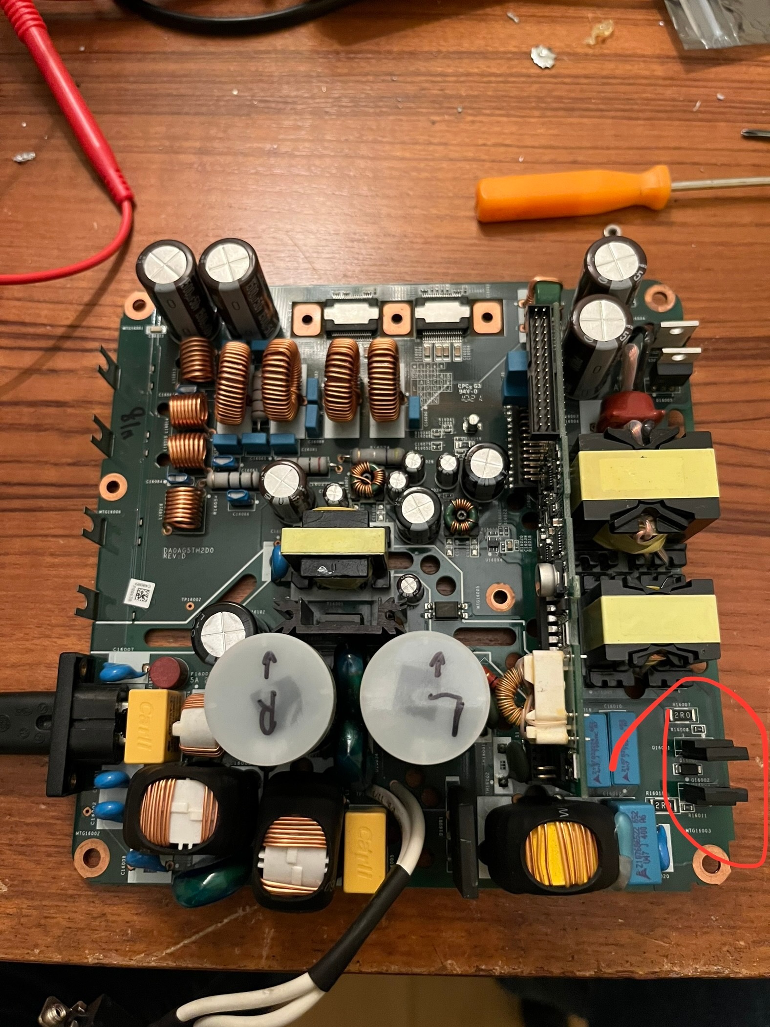
Hi folks, I've got a ZP120 with blown power supply too. When powered up I smell "semiconductors". I've been testing an found both Schottky diodes (D16002 and D16006 text: VC3 type: VS-30BQ015PbF) are broken (virtually shortened 0.06V anode-kathode on the diode tester and 0.46V in reverse direction). It seems these are between VPRI and the drain of the Mosfets on the back. Of course I can replace both but just wonder if this is a sign of the main problem. A bit suspect both have blown. The mosfets seem to be okay and also the other pair of diodes in the same circuit (U3J - MURS360T3G; ultrafast rectifiers). Any suggestions?
I don't have a unit open in front of me. Can you take a pic of your unit and circle the parts in question.
I know them better visually then by ref-des.
They sound like the 36V supply rectifiers. Could be them or you have a short on the 36V rail. I have seen both problems.
Remove the diodes and see if the parts are shorted.
I know them better visually then by ref-des.
They sound like the 36V supply rectifiers. Could be them or you have a short on the 36V rail. I have seen both problems.
Remove the diodes and see if the parts are shorted.
hi
i have Sonos CONNECT:AMP ac190v can on and working ac 230v cannot on not working can you help me
Page 5 / 17
Reply
Enter your username or e-mail address. We'll send you an e-mail with instructions to reset your password.