The amp has no power. Is there an internal fuse for this unit?
Has anyone taken one apart?
Page 1 / 17
For your Information:
Sonos products are not designed to be opened and repaired out in the world, and we do not provide any resources or replacement components for doing this. The warranty services for Sonos components also does not cover units that have been opened in any way.
Even if your player is outside the standard warranty time, we can probably still assist with a replacement as long as it hasn't been opened. There will likely be a fee for the replacement if it's out of warranty.
Anytime a unit fails, we want them to come back to us when possible so that we can review what happened and make adjustments if there's need.

New PWMs and SCK 054 Thermistors finally came in from China. I replaced them and just as I thought, the PWM pulls down the voltage. Checked at 13.03V on pins 1 and 3 on the PWM 😉 Fired up the dim bulb and it went dark. Shut off the power and put the wifi cards back in. Moment of truth... fired it up again with the dim bulb... and the white LED flashed.
Waited a few minutes and opened the iPhone Sonos app. Bob is your Uncle! There it was in all its glory and works!
The Sonos lives and is revived. Total cost for replacement parts: $3.00. Total opportunity cost (I almost tossed it)... $500. Savings to fix it myself: $497.00. Priceless.
I want to personally thank @gruv2ths for the insight on this, and @chicks for the dim bulb ideas. That sent me on a Youtube and reading spree that gave me the tools and confidence to diagnose and fix the problems. Thanks for all the help!

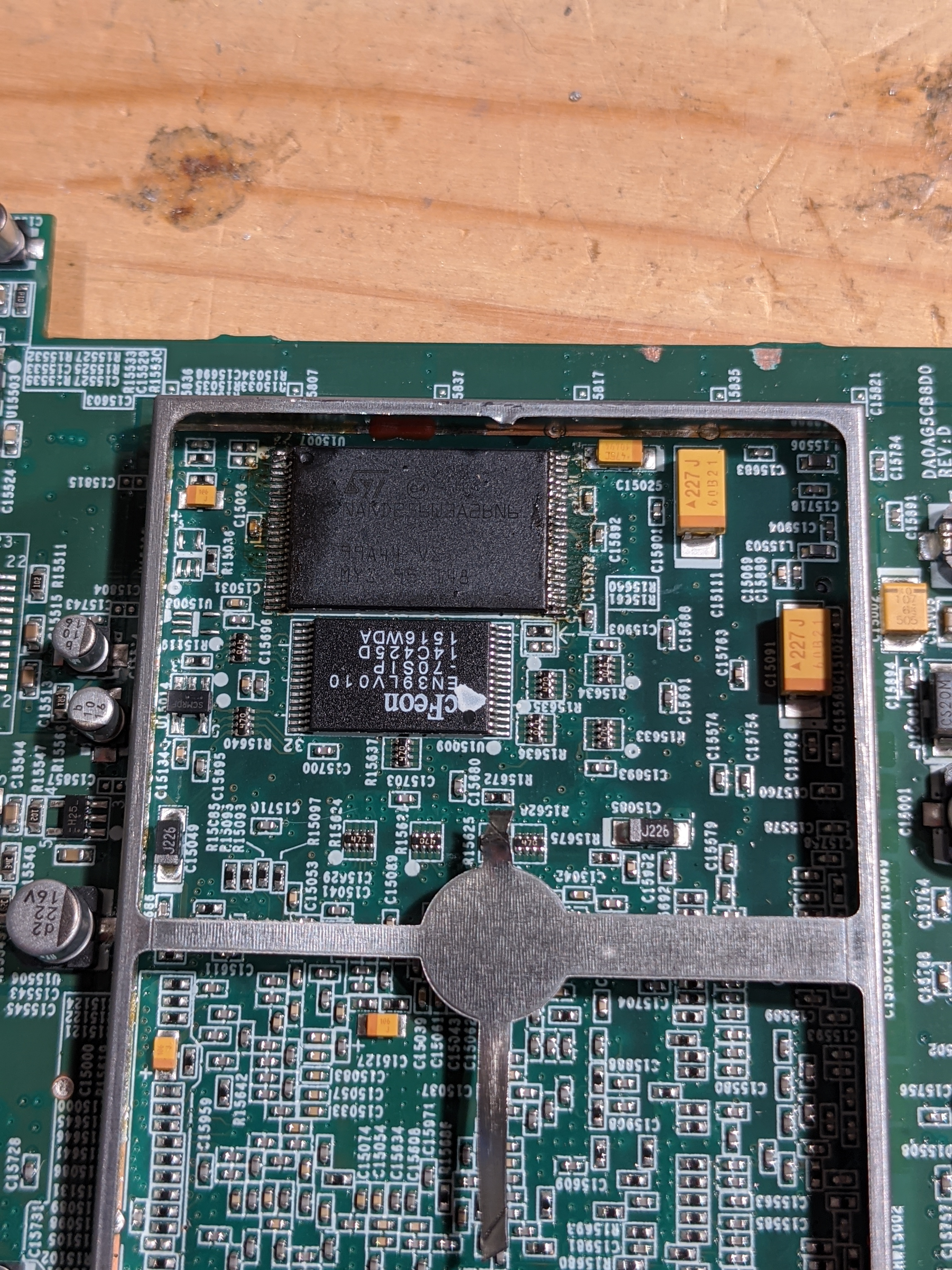
I also tried fixing a wifi/logic card, but was unsuccessful. I had one card that showed a dead short, and another that had a bad NAND chip. I moved the NAND chip from the card with the short to the other card, but it wasn’t recognized. It turned out that the good chip was ‘legacy’ and was a 64MB chip while the other NAND that it was replacing was ‘modern’ and was 128MB. It gave a message of ‘no NAND found’ in the UART, so I’m pretty sure it just doesn’t recognize the chip.
I looked closer at the boards. The two boards did have different DRAM and NVRAM (with the ‘modern’ device having twice the capacity of legacy for both DRAM and NVRAM). However, they did have the same ROM chip (the 512k EN29LV040). So in addition to moving the NAND chip from the legacy board to the modern one, I moved the ROM chip too. After this, the logic card booted correctly!
U-Boot 1.1.1(1-16-3-0.9), Build: 0.9
MPC8272 Reset Status: External Soft, External Hard
MPC8272 Clock Configuration
- Bus-to-Core Mult 3x, VCO Div 4, 60x Bus Freq 16-50 , Core Freq 50-150
- dfbrg 1, corecnf 0x10, busdf 3, cpmdf 1, plldf 0, pllmf 3
- vco_out 400000000, scc_clk 100000000, brg_clk 25000000
- cpu_clk 300000000, cpm_clk 200000000, bus_clk 100000000
- pci_clk 33333333
CPU: MPC8272 (HiP7 Rev 14, Mask unknown [immr=0x0d10,k=0x00e1]) at 300 MHz
Board: Sonos Wembley
DRAM: 32 MB
DRAM test
Test complete - 0 errors, error pattern 00000000
Using default environment
In: serial
Out: serial
Err: serial
Net: FCC2 ETHERNET
Hit any key to stop autoboot: 0
NAND ID is 20:75
32M NAND flash (ST NAND256W3A)
S0 provisionally good, KP=1, G19
S1 provisionally good, KP=4, G18
Boot from partition 1
## Starting application at 0x00400000 ..▒TTTTTTTTTTTTTTTTTTTTTTTTTTTTTTTTTTTTTTTTTTTTTTTTTTTTTTTTTTTTTTTTTTTTTTTTTTTTTTTTTTTTTTTTTTTTTTTTTTTTTTTTTTTTTTTTTTTTTTTTTTTTTTTTTTTTTTTTTTTTTTTTTTTTTTTTTTTTTTTTTTTTTTTTTTTTTTTTTTTTTTTTTTTTTTTTTTTTTTTTTTTTTTTTTTTTTT...........................…
It is only recognizing 32MB of DRAM despite the card actually having 64MB, but that’s what I would expect given the ROM and NAND chips came from a legacy device that has only 32MB.
I’m definitely a happy camper, having salvaged a working logic card from two previously dead ones! here’s a pic of the board after I swapped the NAND chip (but before I swapped the ROM)
Thanks. I would like to share a couple of items that may help others...
I have no idea what kind of solder that Sonos uses, but it is insane. In order to get it to melt, I had to get my Hakko iron up to 900 degrees. 700 (its default) would barely get it to melt. Getting it off components was a chore. That PWM and heat sink took a good 45 minutes to get off along with about 2 feet of desoldering braid. I am surprised I didn't destroy contacts as I really had to put that iron on for a while to get that solder to move. I tried a desoldering pen too, but to no avail. The best way to get it off was keep cracking at it with desoldering braid. I would love to hear if anyone has any hacks or ways to deal with such a problem.
Also, the dim bulb was brilliant. What a great tool to build. It is critical for testing any sort of power supply to keep you from blowing more components. Without this, I would have destroyed multiple resistors and thermistors that kept blowing. I built this for about $25 and you can get the parts at HomeDepot:
https://www.youtube.com/watch?v=rDe6oLKm-ao
This one was nice and clean to make - took about 10 minutes. This helped me trace the hot part. A 60 watt bulb seemed to do the trick for finding the failed component. I tried a 200 watt bulb and it let too much power through, so the bad components would get raging hot quickly. From my readings, the hot part is almost always the culprit for a failed component.
The best resource that I found for fixing and diagnosing power supplied is here:
http://www.electronicrepairguide.com/Smps-repair.html
The guy sells a PDF book that details everything from how to test different components to what tool to use. He has a nice chapter on a dim bulb tester. That site and doc really walks through the different sides of a power supply and what to look for. IMHO, that was invaluable.
Anyways, I really hope this helps others. This was a great learning experience and has given me the confidence to perhaps start hunting for bad Sonos products on eBay and fix em up. ;-)
Final words... I really want to encourage people to post in these forums for help. We CAN fix these things and with a great community like we have here, we can keep these things running. 🙂

Hi guys,
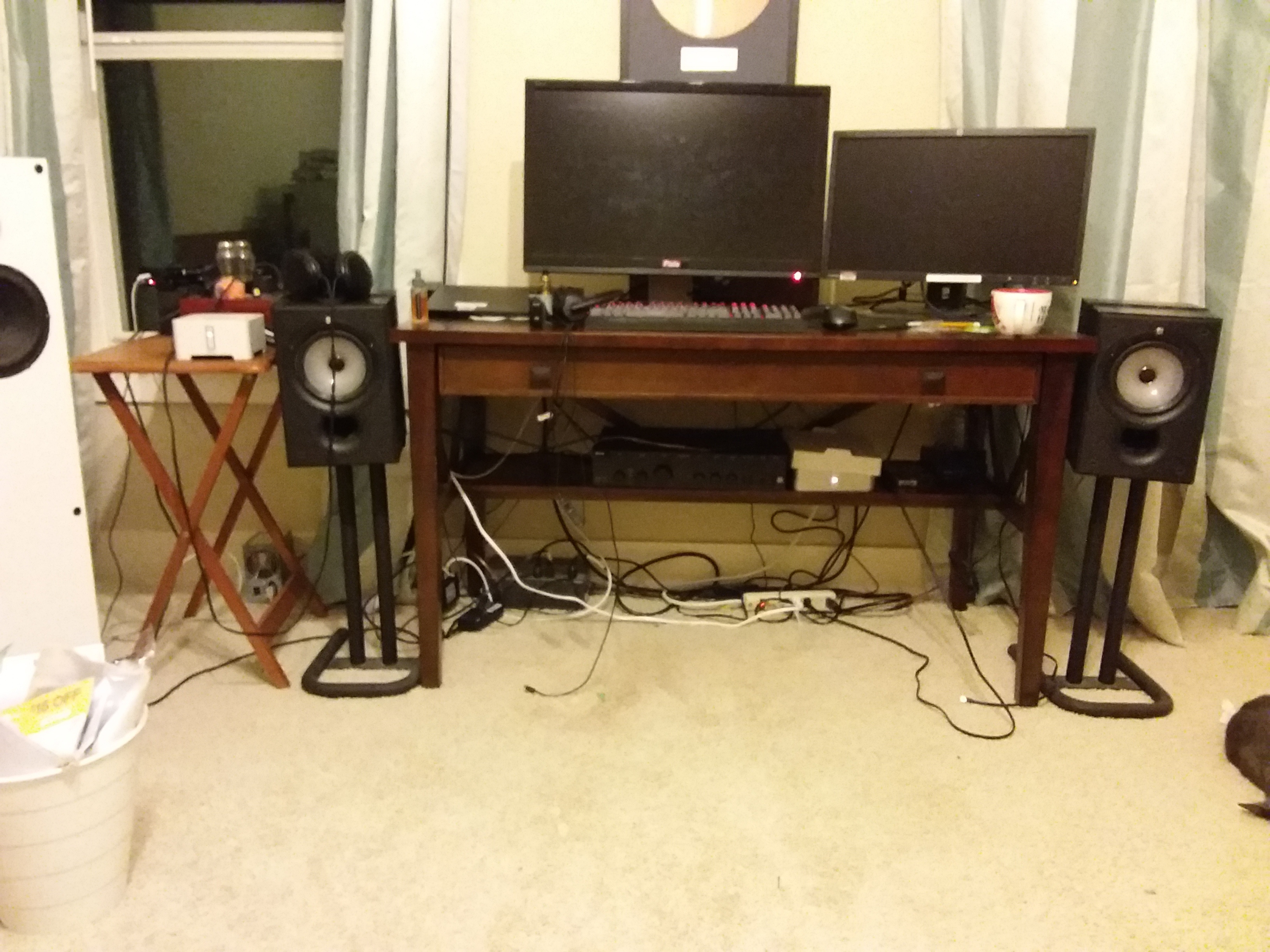
I have a great news to report, I found I was shorting the transformer contact after I installed the mainboard, I was really lucky nothing damaged. I isolated the contacts and guess what, the white LED turned on right after power on! It took me no time to add the zp120 to my Sonos setup and it is driving my KEF speaker replacing the Arcam:
The white box under the table is the zp120, the one one the small table is the zp90.
My next steps are to put everything together and fix the wifi antenna.
Thanks again for the help. I like this forum, I hope with my little experiences, I can help someone in the the future.
@brumster, yes those are thermistors part# SCK-054. Also hard to find here in the US.. I’ve found those on AliExpress as well.
I am glad that I figured out after reading all the other posts in this thread, it is really helpful:
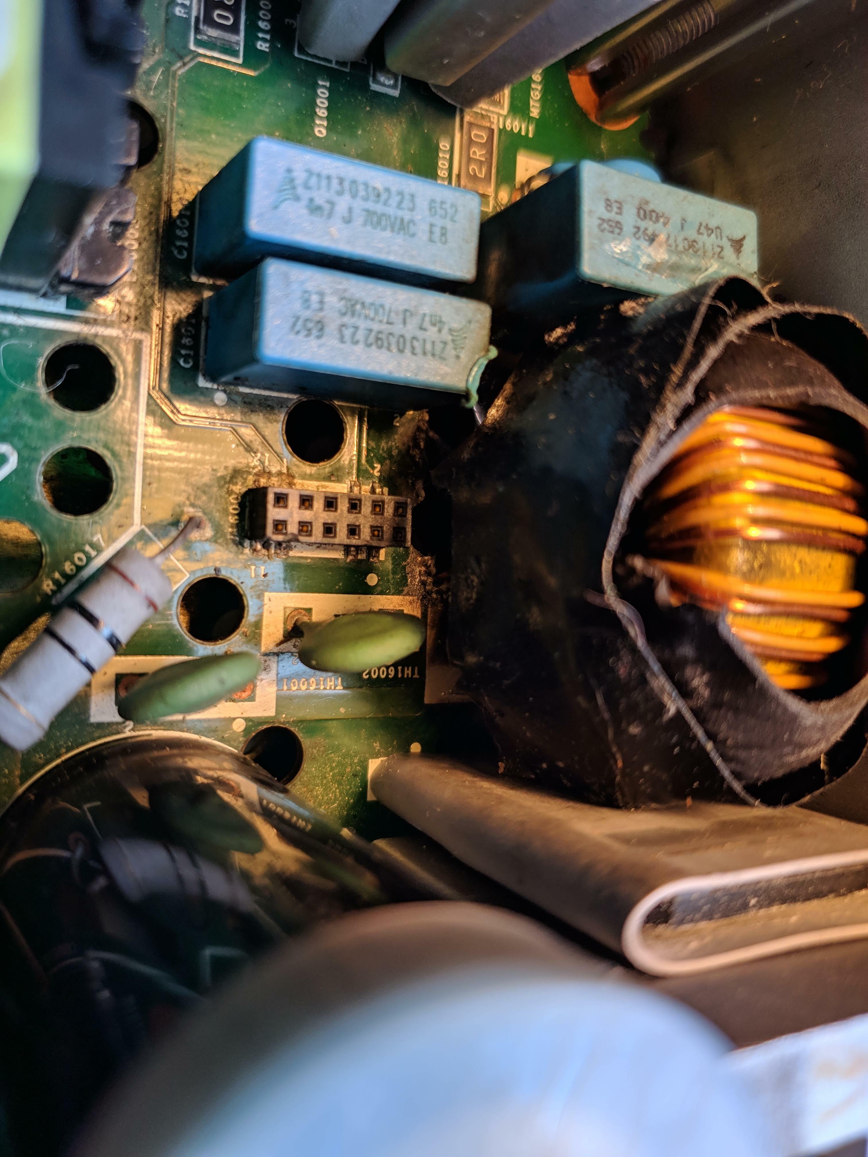
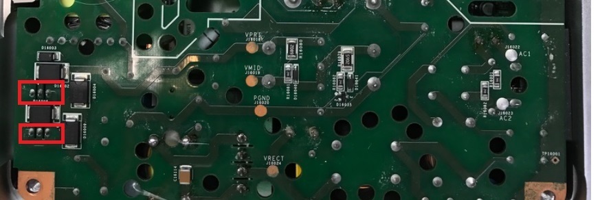
It turned out the burned PCB indeed destroyed one of the traces from the rise card to the 3 pin diode. I could not really visualize it but the meter told the truth. I removed two capacitors and solder a thin blue wire as you can see in the picture.
With this fix and as soon as I start playing music, I did get 36V and the white/orange flashing is gone.
It is amazing with such bad burn in the inductor that the PCB got a hole underneath it but no other components were damaged including the fuse!
Thanks again for this informative thread.
That's some sketchy paranoia right there.
That was it! I replaced the shorted diode with a 1n4148 as that's all I had on hand. No more orange light and she sings!
I have to thank everyone that participated in this thread, wouldn't have gotten her working without your help.

So as promised above I have repaired my new ZP120, and another 120.
The first one:
Just the input bridge rectifier has a shorted diode that blew the fuse. Once the bridge was replaced it has worked fine.
Second one:
SOmetimes it came up no led, totally dead, other times it came up and would get 1/2 way through setup before crashing my network.
Noticed a primary side 350V 33uF electrolytic cap was toast. Replaced It and nothing really changed.
This one was a real head scratcher. The blown cap belonged to what appeared to be power converter circuit that provides biases around the board. Noticed that the GND test point had no continuity to the outputs of the tapped winding. I probed a good working ZP120 and found that all of the outputs of the bias converter were grounded together. So I shorted the return of the tapped winding(8.5V and 15V outputs) to the return of the single winding (3.3V output). Was nervious to power it back up, so just in case i used the dim bulb and it worked great. Replaced the dimbulb with the fuse and I am in business.
I did a chart so my crappy memory will have some help next time i tange with a ZP100. See below.

, but this unit was water damaged and my guess is that it was probably rusted out.
At this point I recommend a thorough cleaning of everything. Residual from that liquid can cause future trouble. Soda spills are some of the worst because the residue takes on water from the atmosphere and forms acids that can cause unwanted conduction paths and eventual trace and component failure.
I put together a little procedure for removing the bias converter PWM.
Awesome stuff! I was able to remove mine w/o removing the caps but it certainly would have been easier w/o them. One tip... the heat sink paste Sonos uses is really cheap stuff. If I didn’t know any better I would think it’s just white lithium grease. If you remove the PWM, clean it and use the arctic silver 5 thermal paste. It will distribute the heat much better.
I just purchased a CONNECT: AMP from eBay. The auction description says it does not power on and I am hoping to use this thread to troubleshoot and fix it.
@m0untainman and @gruv2ths: Can you tell me where you purchased your part from?
Thanks,
Andy
First bust it open and find what may be bad. Follow some of the diagnostics in this thread. It can be one or multiple parts. For me it was 3 parts. A dim bulb tester is your friend and without that, expect to blow even more. The fact that it will not turn on is a semi-good thing as its a pretty decent bet its the power supply.
As for parts, you can try Mouser or Digikey. But as gruv2ths said, some of them are exotic parts and difficult to obtain in the US. The 2 places I got mine from are Aliexpress and eBay. They will likely come from China/Hong Kong/Taiwan, and expect a solid 20-30 day wait. They are all obtainable.
Feel free to ask questions here and we can try to help you on your quest to fix this.
Well I got the STA508 removed and the short has disappeared! I am hoping that this is the cause of the failure. I found a US seller on eBay and wanted your opinion to see if this is the same part: https://www.ebay.com/itm/121059786762?ul_noapp=true
After PMing gruv2ths, I am going to try putting the amp back together and powering it up with the STA508 removed. He said it should power on without it if there are no other issues with the amp. I will update this thread later today with my findings!
Wish me luck and fingers crossed!
After PMing gruv2ths, I am going to try putting the amp back together and powering it up with the STA508 removed. He said it should power on without it if there are no other issues with the amp. I will update this thread later today with my findings!
Wish me luck and fingers crossed!
@benbendog, Congrats... "Bob is your uncle"
Always good to hear when someone fixes it, because Sonos won't 🙂 Nice work.
Always good to hear when someone fixes it, because Sonos won't 🙂 Nice work.
Is there anyone here that is willing to repair a ZP100 or ZP120. I am on my 2nd iteration of each of these. One was replaced out of warranty by sonos (thanks), the other not. I know the end is nigh. Thanks
They are varistors. Part# TVR14241. So far, the only place I found them were on AliExpress. Your amp will work without them but I wouldn’t operate it for too long as they are there for protection.
I forgot to attach images to my previous message. Here they are… the mosfets are marked in red boxes.
Hey Toden,
You probably have this fixed already, but if not the 74VLC06AD on mine was bad. You can download the datasheet and buy them from the link below. From the datasheet look at the pinouts and measure the outputs to ground and see if any are low resistance like 100 ohms or so. One of mine was, and that fixed my problem.
https://www.mouser.com/ProductDetail/Nexperia/74LVC06AD118?qs=sGAEpiMZZMutXGli8Ay4kDE4J8KCiPsFeMuB44hEVa8%3d
To anybody else, I have a repaired power board for sale on ebay. Let me know if you have trouble finding it.
Fantastic - Nice job!
Re my ZP100...
The problem it had was that it was not getting any output on the left channel, and within the app it was detecting a fault. This fault caused it to reset the volume to low levels. This made it unusable as an AMP and also not particularly useful to use the RCA outputs. (I'm not sure -- maybe I could have set those to fixed output -- not sure).
In any event, I opened it up today and couldn't see anything wrong with it. However, during my poking around inside, I must have bridged something... I think It was from the AC to DC board to the chassis as I tried to measure the DC voltages there. There were fireworks and popping. I quickly unplugged it.
The interesting thing (to me) is that it is actually more usable now than before! I took the whole thing apart looking for blown capacitors or anything similar. The only thing I found was the both STA505 chips were quite obviously blown... they both literally had pins missing/blown off (see the image). I figured it was very dead and reassembled it to prove it. Lo and behold... It booted up the first time. Not only that, but it stopped throwing faults! There was no audio on either speaker (not surprising given the amp chips were dead). BUT... both RCA outputs were working. SO despite my boneheaded mistake, I now have a device that can at least be used as a sonos connect (no AMP).
I'll probably try to replace the AMP chips. I have two STA508s. These are the chips that are used in the ZP120, but they are pin for pin compatible with the STA505s that are used in the ZP100. I imagine that even if I am successful in replacing the AMP chips (no small task), there is a high probability that there are now other problems on that board, given the fireworks. On the other hand, the blown pins on the amps look to be only the positive and negative supply pins (4,5,6,7,12,13,14,15). If the board traces survived, maybe all the damage is isolated to the amp chips.
All. voltages seem good EXCEPT I never get 36V between GND36 and 36V it sits at ~15v. When the volume is turned from 0 to anything I get a blip of sound (quick drop to 13-14V) and then orange flashing light, with the volume bar jumping back to ~15%.
I suspected the 14 pin IC on the logic board gruv2ths mentioned solved his similar issue. I swapped the entire logic board with a known good one and same thing.
Where is this 36V supposed to come from? Do I have a switching issue? voltage issue? OR are the amp chips gone? Need a push in the right direction to identify what's failing.
The 36V only becomes active above a certain volume threshold. I found some sonos patent information a while back - this approach is what allows the unit to be low power until higher power is needed (ie when it is actually amplifying), and this is why leaving them on continuously doesn’t create a lot of heat or use a lot of power.
So the 15V you get at the 36V point is ‘normal’ when the device is in standby or at low volume, but when you hit play or turn up the volume then the 36V should come alive and the 36V point should read 36V.
I believe that the 14 pin logic chip is what controls the on/off status of the 36V. That is located on the top logic board. I recall gruv2ths saying somewhere that some of the 36V control circuitry (perhaps a recitifier) is on the riser board. You might try to swap that riser to a known good one and see if your problem goes away or not. Once you have the top logic board removed, the riser just pulls straight up.
I think that if the amp chips are gone, then they could be causing a short that is affecting the 36V. Hopefully that’s not the problem.
Piperdog,
Have you ruled out a problem with the low pass filter (LPF) of the class D amplifier? The noise you hear may be "switching" noise leaking through the LPF...the electrolytic capacitors may need replacing.
Have you ruled out a problem with the low pass filter (LPF) of the class D amplifier? The noise you hear may be "switching" noise leaking through the LPF...the electrolytic capacitors may need replacing.
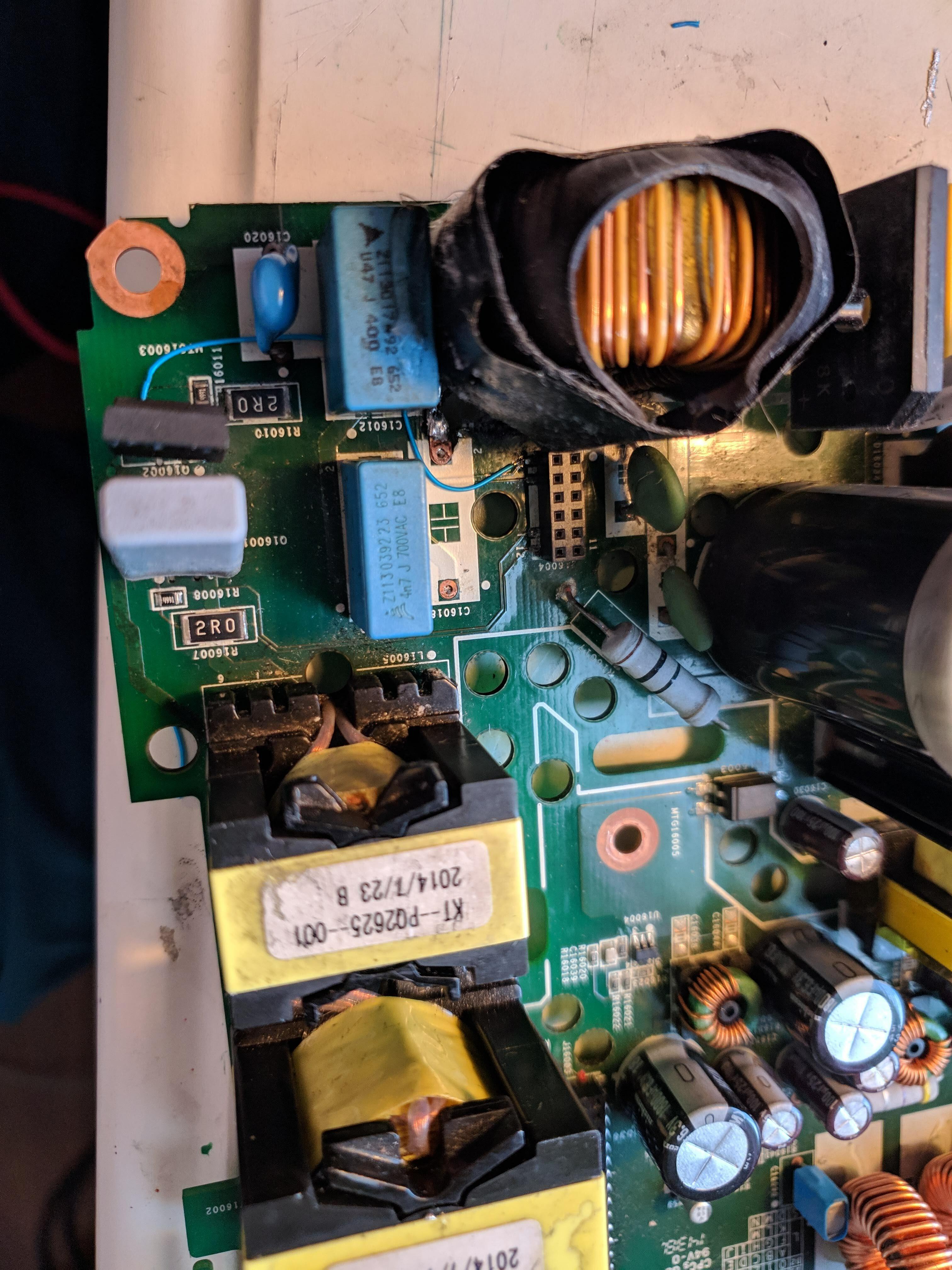
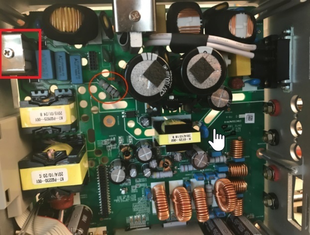
Wow, that shot with the light behind the PCB was amazing! Well done!
I forgot about that coupled inductor. That guy conducts ALL of the primary power. One small nick in that mag wire will cause the inductor to blow open and no voltaje, in a very ambiguous way.
So given where you are, primary power restored, i would get a datasheet for the bias converter PWM and get to work. In this thread there are some nice test point references to show you what you should get with a working unit. Take a good look around the PWM pins on the bottom for corrosion.
Pro-tip: the bias converter is a very standard flyback converter. If you google flyback converter you will get something similar to what you have in the AMP. Look closely in the primary winding snubber. Also check the 10ohm high wattage through hole resistor, it provides power to the transformer primary.
Page 1 / 17
Reply
Enter your E-mail address. We'll send you an e-mail with instructions to reset your password.