The amp has no power. Is there an internal fuse for this unit?
Has anyone taken one apart?

Page 10 / 17

OK I have an update. I successfully built and tested the dim bulb tester today and decided to plug the connect:amp into the tester to see what happens. I was expecting the bulb on the tester to glow bright indicating a short, however the bulb went momentarily bright and then quickly dimmed out. I am using a 60 watt bulb in the tester btw. I don't have time to open the unit right now, but I was hoping the m0untainman or someone else on this thread might be able to tell me what my results indicate.
Thanks in advance,
Andy
Thanks in advance,
Andy
Hi Im not tech enough to open and start fixing mine.
Could there be anyone that could fix mine?
Ive talked to Sonos, but no help there. It online and apparently “working” but no sound.
Cables and speakers working fine.
PM me - maybe I can help.

This indicates that you dont have a short nor a blown fuse. Did you say that you get any blinking light?
Hi Im not tech enough to open and start fixing mine.
Could there be anyone that could fix mine?
Ive talked to Sonos, but no help there. It online and apparently “working” but no sound.
Cables and speakers working fine.
PM me - maybe I can help.
Looks like a lightning has toasted something?
readings at the pins. I thought I could not test this because when I power on the device it blows up. I
I have an educated guess about what is wrong with your device. If you replaced the PWM and it still doesn’t work, then I’d check the two mosfet devices identified in these images. Look for a short between the various pairs of pins (you should not find any 0V drops if you test the 6 combinations with a diode tester). If you don’t have a diode tester, you can just remove the 2 components and see if the device boots up.
These devices are part of the circuit that is used to generate 36V power that is used to drive the amplifier. It is only active when the device is actually playing music. An otherwise working device will boot up without them, and will even play at very low volume. After booting up without the 36V present, you won’t be able to turn up the volume, and the device will start flashing amber. This isn’t permanent and it will go away once you replace the mosfets.
When the time comes, be aware that the silver clip on the top can be a pain to replace. It can be bent open with two sets of pliers so that it is just a bit narrower than the diodes it covers. That will let it do its job and it will be much easier to replace.
thanks! I found a short on the mosfet side, but to be sure, I also want to replace the schottky diodes on the other side… Do you have any idea on what replacement part to order for these?
Thanks gruv. That what I thought too. When I plug it in, no lights, no burning component smells. I do see the table lamp beside the plug flicker momentarily like the amp is drawing power. That seems normal.
Hello, im from Germany and need your Help.
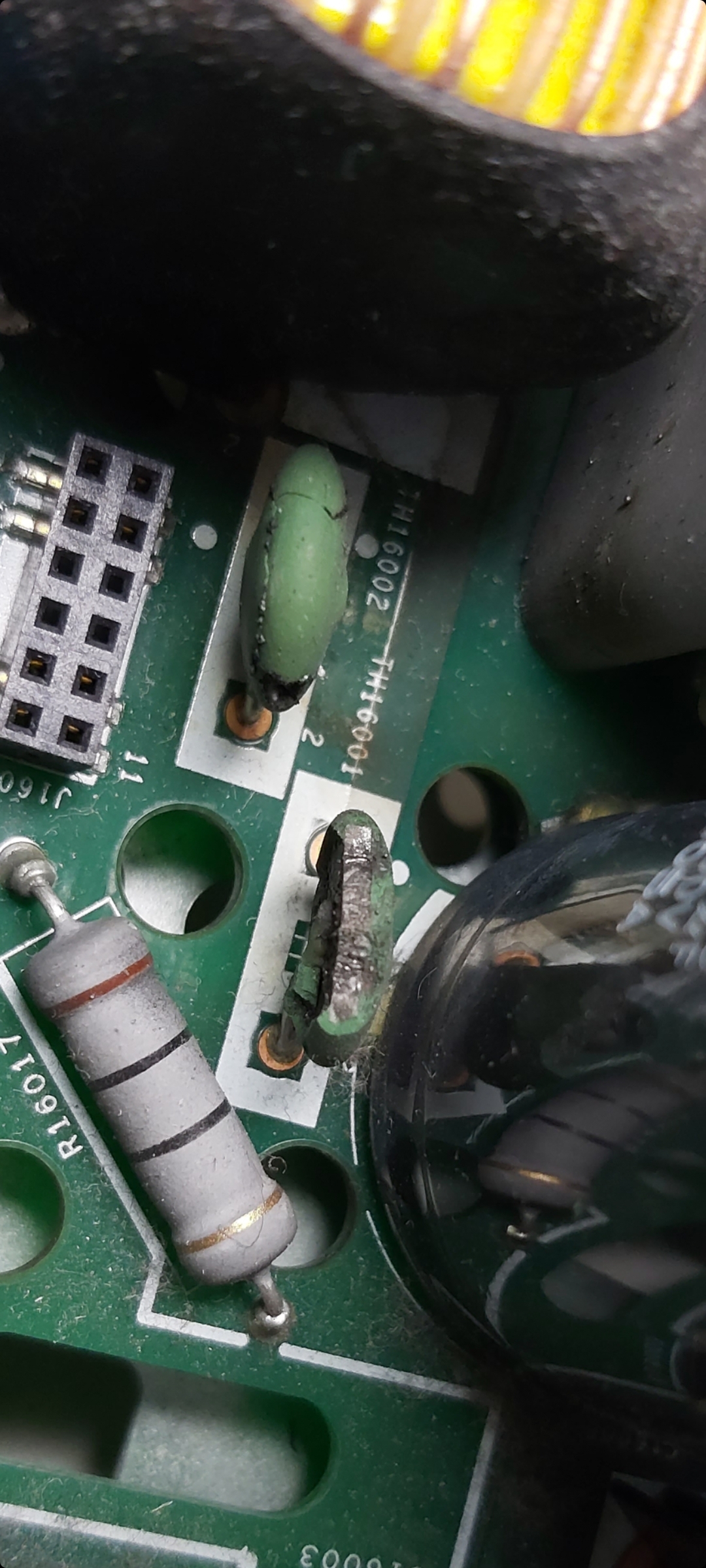
These two capacitors are defective. do you know the data for these?
TH16001 and TH16002.
Thank You
Max
Yes, you are charging the big input storage caps. That is what is making your dim bulb tester glow.
Please please please respect the high voltages that you are working with. Keep one hand in your back pocket while probing or doing anything with a live circuit. Your dim bulb is at high voltage too!
Please please please respect the high voltages that you are working with. Keep one hand in your back pocket while probing or doing anything with a live circuit. Your dim bulb is at high voltage too!
Will do gruv and thanks for the warning. I have worked with electricity at different voltages from 125V house to low 5V circuits but never really worked with power supplies. I suppose I am going to have to open this thing and start a visual inspection to see if there is anything indicating what the problem could be. DO you have any theories?
Userlevel 2
 +1
+1
Add me to the list of non-working ZP-120, I’ve read through this thread many times trying to gather as much information as possible.At this point the unit, which I purchased at a swap meet, and had never been opened, will not power on. I did find a open 5A fuse but replacing it didn’t make any difference. There are no obvious damage and I have checked the usually diodes and transistors for shorts. Everything I am seeing for in circuit test looks good.
I think I may eventually map out the schematic and post here but for now I have traced the 110ac input all the way to the first bridge rectifier, from ground the positive side of the rectifier is 60vdc and -60 to the negative side. Which seem reasonable..this is where I’m not to sure to go after this.
New Information:
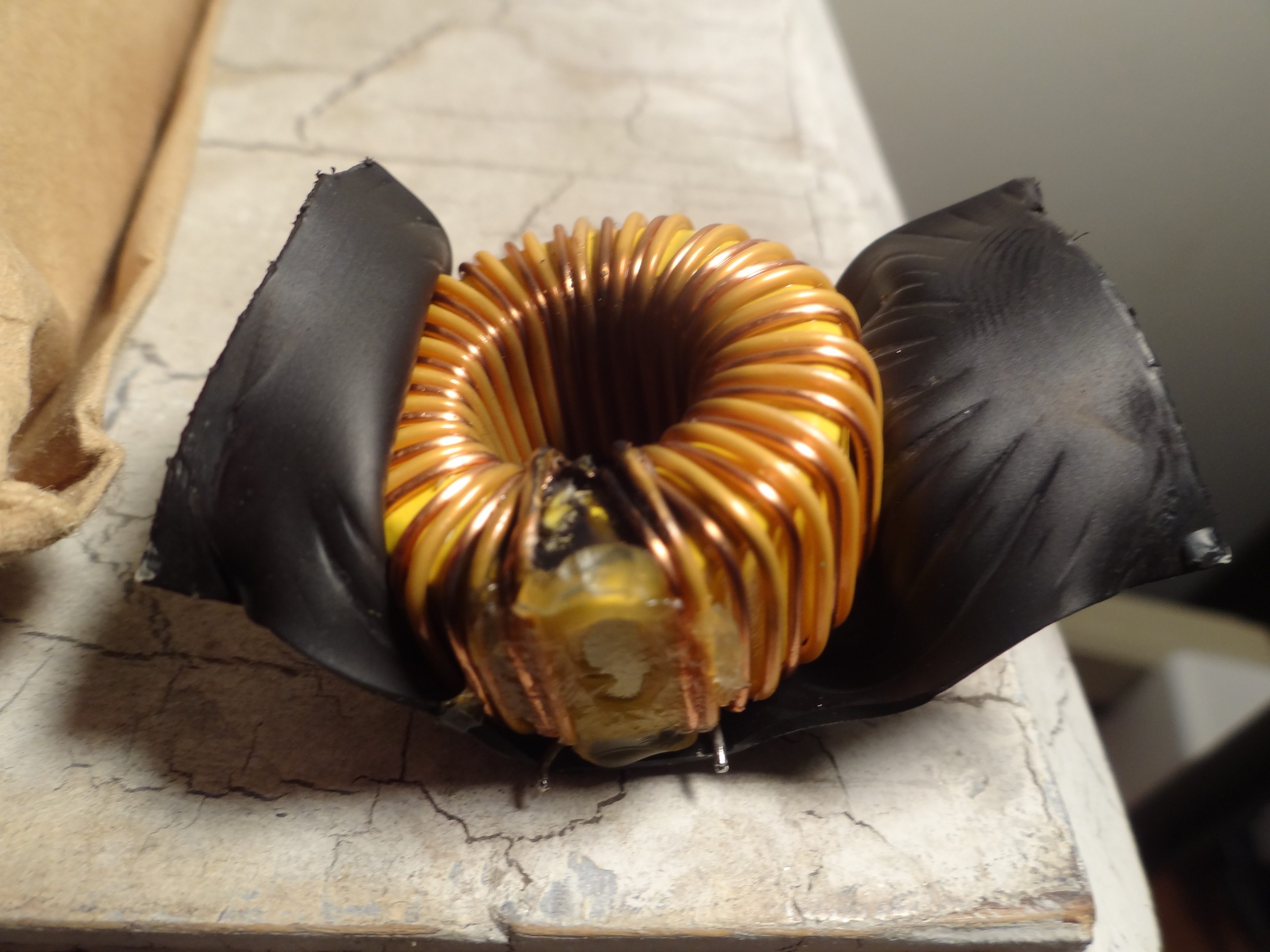
I knew I was in the right place, L16004 is bad, the question is, can I source this part or is it custom? Maybe I can unwrap it a bit and re-insulate...
If no source does anyone have one from a parts unit? Thanks!
I would start with the bias converter.
It sounds like it is not doing anything.
Scroll to the first page of this thread (I believe) and see the test aid that I made. Probe and check for those voltages.
It sounds like it is not doing anything.
Scroll to the first page of this thread (I believe) and see the test aid that I made. Probe and check for those voltages.
gruv: I opened the amp and checked some of the voltages you referenced on your page 1 post and all check out except the 15.4V P-FET voltage. I only had .3vdc on that. One question on the winding voltages. Did you use the RTN points or GND when checking?
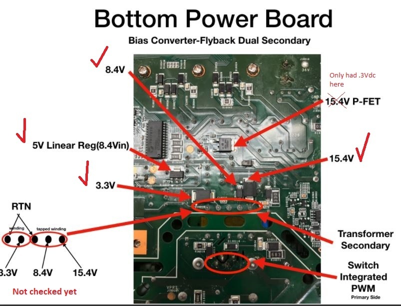
After reading m0untainman's post on page 2, I saw he used the RTN so I checked the voltages on the secondary and it is not registering any voltage at all (0V). I am thinking the issue is the PWM.
Hi Max. Those are both NTC thermistors (not capacitors). They can be replaced with part # SCK-054.
They act as 5 ohm resistors at room temperature. As they warm up, their resistance drops. This prevents a large amount of current inrush at power up.
In a pinch, you could try replacing them with jumpers, but I would only do that if you are powering the board with a dim-bulb (as described earlier in this message thread). In that case, the incandescent light bulb will limit inrush current.
Got it to play music yesterday. Sounded great after such a journey.
One thing, it was not very consistent. On high volumes, it sounded great but down low there was some cracking.
Booting it up today, I only get a slow flashing orange LED and sometime a very dim white light. I am getting 15V on the 36 pad and 36V when I play some music through the app. That all works fine.
I started digging deeper (on the secondary side only, assuming the primary works perfect) and found that on only one of the two shottky diodes, the middle pin is getting 15/36V. The most outer one (diode, not pin) is getting voltage while the more inner one is not getting anything. What are these middle pins connected to? As I do not find an immediate link probing my DMM. The two outer pins are ground I assumed.
If you are getting 3.3, 15.4 and 8.4 then the PWM is working fine.
Make sure the 2 RTN pins are shorted together. If they are not shorted, short them. (dim bulb in all of the time)
Make sure the 2 RTN pins are shorted together. If they are not shorted, short them. (dim bulb in all of the time)
I have had this exact thing happen but on the 36V output filter. Where is this again on the board?
I definitely would fix that.
just extend the wire with a small piece of wire and insulate the connection with shrink tubing.
This fail means you prob either had a nick on that wire (winding) or you have a nick on the wire and a short down stream that made the nick show itself.
Either way fix the inductor and make sure nothing is shorted.
Dim bulb would help here.
Thanks gruv. Can you tell me what I will be looking for when I short the 2 RTN pins?

thanks! I found a short on the mosfet side, but to be sure, I also want to replace the schottky diodes on the other side… Do you have any idea on what replacement part to order for these?
If you are referring to the pair of TO220 Schottkys mounted to the case, those are 10 Amp 100 Volt. Part number SBR1010CT
Userlevel 2
+1
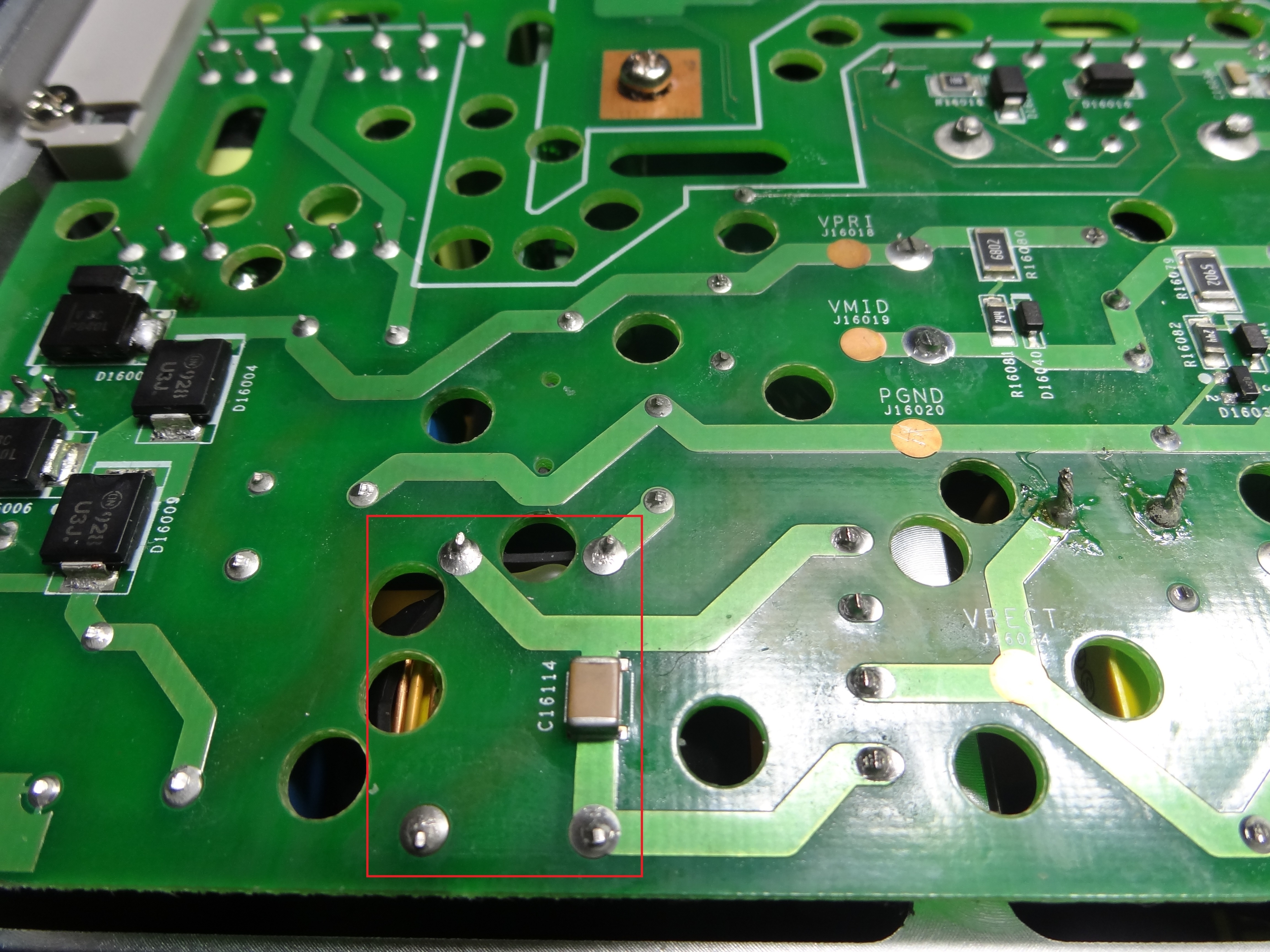
See image...in red, on the dc output of the bridge.
Definitely looks like a nick in the wire.
I’ll report my status after I repair the inductor.
The 2 RTN pins are shown in the pic above.
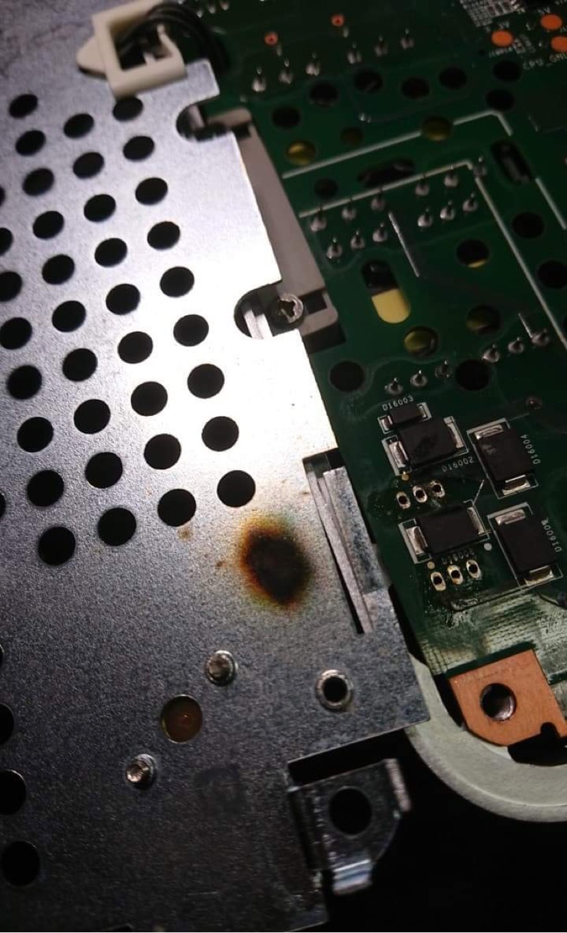
That is likely not beyond repair!
It’s hard to tell from the picture, but there are 6 components under that area and likely at least one of them is bad.
There are four large flat diodes. These can be tested with a multimeter to see what the forward voltage drop is across each. They should conduct power in one direction only.
The other two components are on the other side of the board. They have 3 legs each, and are power mosfets. (like this: http://www.datasheetcafe.com/k3797-datasheet-mosfet/). You can test like a diode between each pair of legs. You should not see any short circuits.
The mosfets are part of the circuit that provides 36V to the amplifier. That 36V is not actually required for the device to power up properly. The fact that you don’t have power means that there is another problem. It could be as simple as the fuse being blown. That is on the other side of the circuit board, and is a small short cylinder about 1cm tall (usually brown).
Do you have a multimeter to test, and have you ever done electronic soldering before?
Sorry, I meant assuming no other shorts or issues, should the amp power on if the RTN points are shorted? I should have some time tonight to take a look at it and will report back.
Thanks again gruv2ths for all your help.
Thanks again gruv2ths for all your help.
Hi Tim, thank you. I have now ordered two of them. Can I destroy them by changing the AC voltage from 230V to 115V on the 230V grid?
No probably not, those 2 points need to be shorted though for the AMP to work right. Light in the front should blink either way. Not sure what would cause the light not to blink with a good working bias converter.
Page 10 / 17
Reply
Enter your E-mail address. We'll send you an e-mail with instructions to reset your password.