The amp has no power. Is there an internal fuse for this unit?
Has anyone taken one apart?

Page 11 / 17
Hi Tim, thank you. I have now ordered two of them. Can I destroy them by changing the AC voltage from 230V to 115V on the 230V grid?
Yes that could cause a lot of damage. The usual rectification generates the input times the square root of 2 as DC voltage. SO 115V input translates to about 162V. The switch on the back adds a voltage doubler to the rectifier circuitry. With a 115V input, that produces 320V internally, which drives the high voltage circuitry. If 115V is selected but the input is 230V, then it would internally generate 640V DC. That could break a lot of things. All of the power passes through the thermistors, and they blew up in protest of the voltage. The question is if they went before anything else ‘downstream’ died or not. It is possible that there was also damage to the PWM chip. This is the four pin device on a heatsink next to the transformer. You can check if it’s pins are shorted or not. If there are short circuits between pins then it is dead. If there are no shorts, it doesn’t mean that it isn’t broken though.

OK so I shorted the RTN pins and no change. Still no power light and the dim bulb tester light came on and then went off. I decided to open the top and have a closer look at the power supply board. That was an adventure 🙂 After finally getting the top off I am stuck trying to figure out how to get the WiFi board off. Daniels guide pointed to the photo stream but that did not provide any help. Any ideas gruv2ths?
EDIT: Never mind, I just found the other hidden screw to the left of the sub woofer analog output. Looking around now....
EDIT: Never mind, I just found the other hidden screw to the left of the sub woofer analog output. Looking around now....
Still no joy. I looked around at all the top components and do not see anything that would indicate a failure. Desperate, I re-probed the original points on the power board and got the same results. The only thing different is I am not getting any voltage on the P-FET that gruv2ths identified. All other voltages match his. I checked the other side of the P-FET and get 15.1V on each leg.
@gruv2ths: Any ideas on where I should check next?
@gruv2ths: Any ideas on where I should check next?

I need to think about this. This is a new one for me, ad I have never heard of this specific failure.
Thanks gruv2ths. I didn't probe the primary side of the transformer because I wasn't sure what pins to probe and what voltages to expect. Do you know? I also emailed the eBay seller to see if he could provide any information on how it failed and he said he did not know. The amp doesn't appear have been dropped, nor gotten wet or anything like that.
Good job with the ebay mail, always good to know how it happened if you can find out.
ALso, what is the voltage across these 2 pins?
ALso, what is the voltage across these 2 pins?
There is 0V across those pins. Since I have never owned a connect amp, can you tell me how long it takes to see any lights after plugging it in?
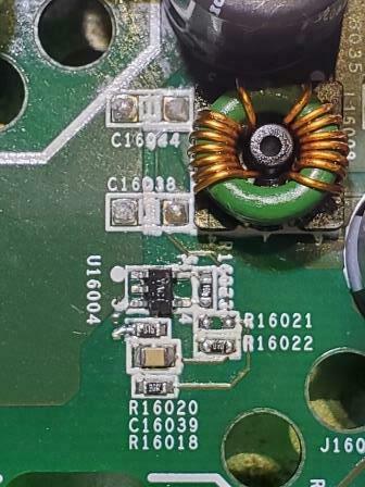
Сould you please tell me the value and marking of the resistor R16021?
The LED in the front come on in a second or so.
Do you have the gray ribbon from the front buttons to the logic board connected? (it connects under the wi/fi card)
Do you have the gray ribbon from the front buttons to the logic board connected? (it connects under the wi/fi card)
Hi Im not tech enough to open and start fixing mine.
Could there be anyone that could fix mine?
Ive talked to Sonos, but no help there. It online and apparently “working” but no sound.
Cables and speakers working fine.
I have no idea what kind of solder that Sonos uses, but it is insane. In order to get it to melt, I had to get my Hakko iron up to 900 degrees. 700 (its default) would barely get it to melt. Getting it off components was a chore. That PWM and heat sink took a good 45 minutes to get off along with about 2 feet of desoldering braid. I am surprised I didn't destroy contacts as I really had to put that iron on for a while to get that solder to move. I tried a desoldering pen too, but to no avail. The best way to get it off was keep cracking at it with desoldering braid. I would love to hear if anyone has any hacks or ways to deal with such a problem. ...
🙂
- The solder was no doubt lead-free, which has a much higher melting temperature than lead-content solder. The solder that is touched directly by the iron will melt but due to temperature drop further away from the iron, some solid solder will remain. Use a solder sucker to get as much solder off the joint as possible. There will probably be some solder remaining in hidden areas which makes it impossible to pull the component out. The heat from the solder iron does not get conducted to those hidden remnants of lead-free solder; so add some leaded solder* to the joint and let it flow in. The leaded solder will mix with the lead free solder and alter the alloy to lower the melting temperature. The added solder provides a better heat conduction path. Suck it clean again. Repeat a few times if needed.
Apply the iron to the component lead, not to the pcb pad. The copper clad of the pc board will peel away from the fiberglass if it get heated too much.
*Rosin core solder can get messy, and the rosin flux is not really needed since the copper has already been tinned. Find a spool of lead solder without a flux filled center in the plumbing department.
Yes the grey ribbon cable is connected. So now something new is happening. I looked at the front of the amp and now have a white(ish) light. It seems a bit dim but I am not sure if that is normal. I tried resetting the amp to factory defaults using the instructions from the sonos site but the light never changes. I am really stumped now 🙂 Gotta go to bed as I have to wake up early tomorrow. I will pick this up tomorrow. Thanks again gruv2ths.
OK so after a few PM's with gruv2ths I started looking at the logic board as being suspect. This is the board with the ethernet and WiFI card on it.On a close visual inspection I found a burned resistor located neat the Ethernet ports. I tried putting my meter on it and sure enough it is open (no resistance) Not sure what the part number on this resistor is but I am suspecting another component in line before it might have failed causing the resistor to blow.
The board does appear to be getting power as some of the small resistors around the burned one are getting voltage readings.
The board does appear to be getting power as some of the small resistors around the burned one are getting voltage readings.

Ok thanks for your fast reply, I indeed looked at the posts before and saw the scheme of all the readings at the pins. I thought I could not test this because when I power on the device it blows up. I will build a dim light tester, check the transformer and the pwm again as well as the diodes. I have a very cheap multimeter with a diode function, is this trustworthy?
Yes even a cheap diode tester should work.
OK I am an idiot. After looking closer at my post from yesterday I am realizing that that is not a resistor that is burned out, but a capacitor (noted by the "C"15011 designation). I have not had a lot of time to sit down with the amp and think I was rushing yesterday which is why I said it was a resistor. It also explains why it was 0L when I tried to Ohm it out 😛 I suppose the next step will be to try and find the value of this cap and see if I can order one to replace it. Any ideas gruv2ths?
After some more investigation I have found that more that more than just the capacitor is blown. The three resistors beside that cap seem to be bad as well as an inductor. Closely inspecting these components showed that the markings have been burned off of the resistors as well as they show open on an OHM meter. Also the inductor seems to be open. The whole circuit seems to be surge protector for the Ethernet ports. This seems to indicate the possible cause of the failure as an unexpected surge in the network cable that was plugged into the amp. I am thinking about ordering all of these parts and replacing all of them.
@gruv2ths: Could you possibly take a picture of this circuit on your amp and post it here? The reason being is I am assuming the burned resistor values are the same as the other side (750 = 75 ohms) but I want to make sure. Also if you have any advice for me I would much appreciate it as I am bit rusty when it comes to component level troubleshooting.
Thanks,
Andy
Userlevel 2
 +1
+1
ok-that what interesting, after I thought I had removed the short from the inductor I soldered it back in mounted on the bottom for evaluation, I had a pigtail 5 amp fuse and brought it up slowly with my variac and the 5 amp fuse blew. I thought I was getting a very high resistance reading between the 2 windings where there should be none, I ended up fully unwrapping the inductor and rewrapping it, put a current meter in place of a the fuse in and slowly brought the variac voltage up,watching the current draw, stayed low and got the white light on front and made it up to full voltage with no issue...now to put the inductor back in correctly and try to connect...looking real good!
ando1, good work. Always look for the burned out components as generally the suspected issue is near. Get those parts and get multiples because sometimes they will blow again when you give them power. So having extras is always good. The dim bulb will lower the chance they will blow again. Once you replace them... probe for significant heat. The hot part is usually the culprit.
If you take a pic we may be able to tell you the values of the components that you need.
Did you double check that inductor and does it have a number on it? The bad news is that inductors can be difficult to track down as many are custom. The good news is it really takes a lot for inductors to blow. So hopefully it’s not bad. One of mine had burn marks on it but still ran like a champ. If it has numbers then we may be able to find it. Pictures will help. I noticed for myself that getting my phone close allowed me to get s better look at the numbers.
Hello,
I read a lot of things but my English is limited, so I will explain my problem.
I have a ZP100 that works from 3 to 40 minutes when it is turned on, then there is more music and it disappears from the application ....
The problem is already may have happened to one of you, and if so how to solve it?
Thank you very much.
Thanks m0untainman. I had to put this project aside for a bit as I have limited time with the holidays approaching. I will try to pick it back up soon. I am starting to think that there may be more wrong with that WiFi board than just those caps and resistors. In looking closer, the circuit seems to be a decoupling circuit to shield the GND side of the ethernet ports. Right now the behavior of teh amp is that once it is plugged into power, the LED will go straight to a very dimly lit state. Since I do not own a functioning amp, from what I read, the LED is supposed to start blinking white and then go solid once the unit has fully booted and connected. Or the LED will flash green when it is ready to be set up on a network. Either way, the dim white LED is not one of the normal function states. I am hoping to score another broken amp. possibly with a power failure or some other failure mode that I can take both broken ones and make a god functioning one. I am a bit sick thinking that I dropped $150 on this one, but I knew the risk and gambled so oh well. Hopefully it will work out in the end.
Thanks,
Andy
Thanks,
Andy
Don't give up too quickly. Order those parts off eBay or Aliexpress. Those parts being replaced may do it, or it may help lead to the true culprit based on what I said in my last response. Burned parts are usually close to, or the actual problem. The dim bulb tester will help you determine that.
I do plan on replacing the burned components and giving it a try, thanks. Would you be able to verify for the values of the resistors circled below? I think the number is 750 but not sure.
I'm actually out of town on vacation for a couple of weeks due to the holidays, so I can't test these until I get back. I have a cap tester to get the values of the C15011 value.@gruv2ths, are you able to pull some values for ando1?
@ando1 - Great photo... looking at your picture, it appears to have liquid damage... looks like it got wet. Pretty good chance replacing the parts and perhaps finding if there is another short may fix it.. Its just a hunch. As stated before... when you do get a chance to replace the components, dim bulb it and see if the light blinks. If not, probe for a warm/hot part nearby...
Also... If those are the 1000uf big caps, that are in that picture... they normally have plastic caps on them to prevent the board from causing a short. I would recommend putting the plastic caps back on them or place some electrical tape over them to shield them from touching the board.
Also... If those are the 1000uf big caps, that are in that picture... they normally have plastic caps on them to prevent the board from causing a short. I would recommend putting the plastic caps back on them or place some electrical tape over them to shield them from touching the board.
@m0untainman - Yeah I was wondering what that discoloration might be on the board. Makes sense it might have water damage seeing that the top of the amp is full of holes 😳 I ordered some of the caps and resistors form eBay. As soon as they come in I will replace and see what happens. Thanks for all the help so far and I hope you have a great holiday!
Page 11 / 17
Reply
Enter your username or e-mail address. We'll send you an e-mail with instructions to reset your password.