The amp has no power. Is there an internal fuse for this unit?
Has anyone taken one apart?

Page 14 / 17

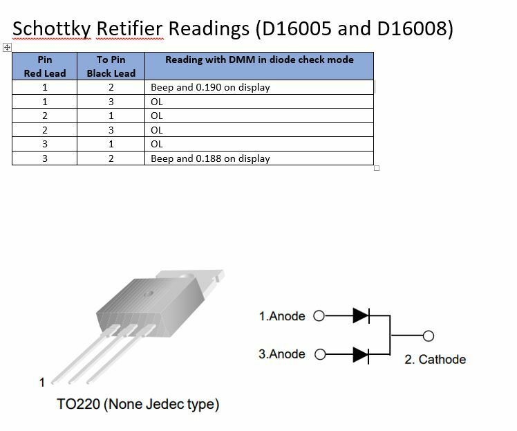
Thanks gruv2ths. If you would measure the following on the rectifiers:
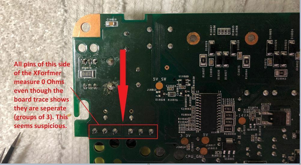
Also if you could check the 6 pins of the transformer that is closest to the rectifiers. When I checked them last night, they were all shorted together.
- pin 1 to pin 2
- Pin 1 to 3
Also if you could check the 6 pins of the transformer that is closest to the rectifiers. When I checked them last night, they were all shorted together.

The transformer is just a bunch of coils of wire wrapped around a ferrite core, so yes with your DMM it will just look like it is all shorted together. That is normal.
As for the rectifier, i believe the outside pins are shorted together on the board and both outside pins should be high resistance to the center pin. Open the datasheet for that diode then google 'how to test a diode'. The package in question is just 2 diodes in one package. This is stuff that is good to know.
A short on the output of the 35V supply may explain why you have 0V on the Pfet. Maybe take your meter in ohms mode and measure (with the power off) the resistance from the pin of the Pfet that measures 0V to ground. I bet you will measure the same short you are measuring at the rectifiers.
Yea I know the transformer should show a short on some pins put it was showing across all even though the solder traces looked like they were on separate circuits. As for the rectifiers I do have the data sheet and did test one that I removed and it tested good. I am planning on removing the other one tonight and test it as well.
Please let me know what you get for your readings. I am especially interested in the rectifier pins.
Userlevel 2
 +1
+1
I thought about that and is definitely a possibility, but I don’t want to think about it because then I fully unraveled an inductor when I didn’t need too! 
But, I did do a pretty good job of rewinding it .
It’s all setup and working!
I do have one heat sink clip I cant get back on, frustrating because I never needed to take it off, but there must be some special tool to spread this clip and get it over 2 transistor casings, I’ve read that it is a bear to get back on...and so far it is.
I removed both rectifiers tonight and checked them while referencing the data sheet. Both seem to check out OK but I am hoping gruv2ths or m0untainman can double check my work and verify. Below are the readings I got from the rectifiers while removed from the board. My meter was in the diode check mode:
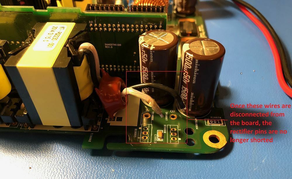
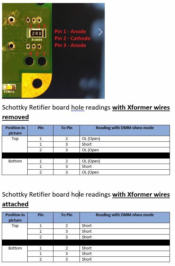
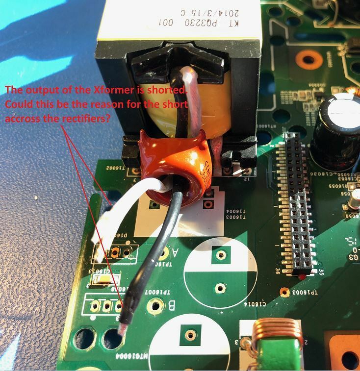
After checking the rectifiers I checked continuity on the board mounting holes where they were mounted and they were all points were still shorted. I then tried removing the 2 wires that were soldered near the rectifiers. These wires are coming from the bigger of the 2 transformers. After removing them the middle mounting hole is no longer shorted to the other 2 on both rectifier mounting locations. Sorry if I am not explaining this well so I am also including some pictures and tables with my findings below.
The end result seems to be that when the 2 wires from the Xformer are connected to the board all of the recifer pins are shorted together. When they are removed, only Pins 1 and 2 are shorted.
gruv2ths / m0untainman - Please let me know your thoughts on this.
Thanks,
Andy
Lots of great stuff here.
Looks like the shiort is not the rectifier.
Like I mentioned earlier, there could be a lot of thing to cause a short at that point. Anything on the 36V bus.
Start taking off the electrolytic caps by one. Start with the 2 Big brown radial ones right next to the rectifiers.
Hope it’s not the Amps.
Looks like the shiort is not the rectifier.
Like I mentioned earlier, there could be a lot of thing to cause a short at that point. Anything on the 36V bus.
Start taking off the electrolytic caps by one. Start with the 2 Big brown radial ones right next to the rectifiers.
Hope it’s not the Amps.
My soldering iron dies yesterday so I have to wait for a replacement to arrive before I can remove those caps. I also ordered a multimeter that has an ESR function to test the caps so I will know for sure if one of them is bad. Should have everything by the weekend and can update then.
Ok cool,
Which meter did you order?
Which meter did you order?
It's kind of a cheap one but it got pretty good reviews: https://www.amazon.com/gp/product/B00EYYJRC0/ref=oh_aui_detailpage_o01_s00?ie=UTF8&psc=1
Also go this soldering iron as the $20 one I had stopped melting solder after using it 3 times: https://www.amazon.com/gp/product/B01DGZFSNE/ref=oh_aui_detailpage_o00_s00?ie=UTF8&psc=1
Also go this soldering iron as the $20 one I had stopped melting solder after using it 3 times: https://www.amazon.com/gp/product/B01DGZFSNE/ref=oh_aui_detailpage_o00_s00?ie=UTF8&psc=1

I’m a bit stumped on a ZP120 and am looking for help. The zp120 had a bad varistor, between VPRI and VMID), with lots of scorched bits when it caught fire. It took out the PWM chip, the fuse and a board trace. I’ve replaced those but still can’t get it working properly.
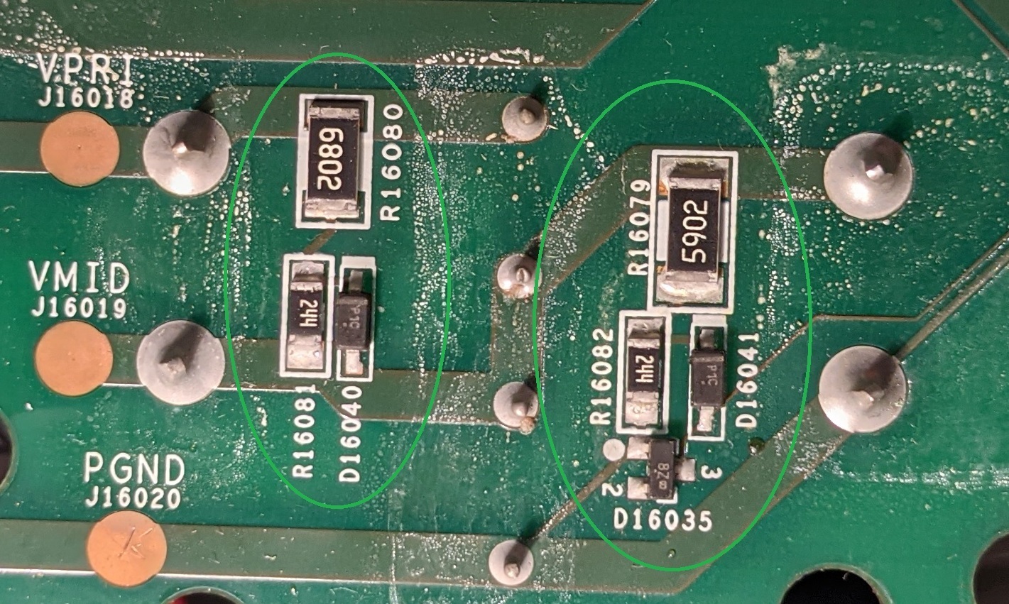
The attached image is from the underside of the zp120 board, below the large capacitors.
I have circled two small circuits in green. The one on the left looks like a bleeder resistor that is intended to discharge the large 1000uf capacitor that sits between VPRI and VMID (about 150V). The 68k and 240k resistors provide 308k of resistance across the capacitor. I thought the small “p1.c” diode is some kind of snubber diode, but I’m not so sure any more, based on what’s going on in the other circuit...
The similar circuit one on the right seems to bleed the 150V between VMID and PGND. That circuit also has the addition of D16035, which sits between the bottom legs of R16082 and D16041. This additional chip is a 19V zener diode in a SOT-23 package. (MMBZ5249B). Pin 3 of this zener diode (which is presumably supposed to be at 19v when the circuit is working property) is the voltage that drives the PWM chip.
My board reads 0V at that junction. I have replaced the zener with no luck. When I provide 16V from an external source, the PWM operates as it’s supposed to. The PWM chip needs 15V to get started, but operates ok with as little as 9V… if I remove my external 16V, the circuit continues to operate (and somehow the circuit now internally generates about 12.5V at the same junction of R16082 and D16041).
I can’t figure out how this circuit works. Specifically, the junction between R16079 amd R16082 reads about 110V when powered up (this seems right given the resistor divider created by R16082 and R16079). I understand that the zener is supposed to clamp that to 19V, but what is the P1C diode (D16041) doing? If it is a regular diode then it wouldn’t pass any voltage to the zener. If it isn’t a vanilla diode, then what is it? I’m guessing D16041 isn’t working but I don’t know what to replace it with. It does not read a voltage drop in either direction when tested (the other P1C reads 0.68V). I can’t find a reference to that marking anywhere.
2 things about the heat sink clip.
- the Mosftet heat sink clip can EASILY bend the thin leads of the Mosfet, so be very careful. You wont know you bent the leads until the fuse blows. (the rectifier leads are much heavier and more resistant to bending) You may want to ohm out the 6 Mosfet pins after the heat sink is installed to make sure.
- Believe it or not i have used a butter knife handle to spread them open and very carefully drop them down into place. Also used a half round file. If you use something abstract let us know so we can add it to the lest. LOL

Hi gruv2ths - I still haven't received my meter and iron yet, but was looking around at the are where the caps are. I don't really see much that can be shorted and was wondering if you might have any theories. I am still going to remove the caps and test them, but wanted to think of the next steps if they check good.
That looks like it is labelled “31B”. EIA-96 says that’s a 2.05k resistor: https://www.hobby-hour.com/electronics/eia96-smd-resistors.php
I measured in circuit, and got 1k. Perhaps it is in parallel with the one next to it.
I took the caps out today and they checked out OK using a capacitance meter. With the caps out, I connected the 2 wires from the Xformer back to the board and all 3 pins of both rectifiers are shorted again. If I remove the wires, the pins measure what they are supposed to. Could it be that the 36V transformer is shorted out? There doesn't seem to be any damage to it.
The MACs are not an issue (I have moved the boards as you describe multiple times).
Support will still talk to you. I actually had them help me get a CR200 working less than a year ago, and that device hasn’t been sold for 8 years now. That required them to remotely log in to the device and provide customized update files, as the device was so out of date that it couldn’t be updated from the main site. I was very impressed.
Good info ando1. The 2 wires will appear to short because its a winding. They should short as that's how a transformer works. See this to understand why:
https://en.wikipedia.org/wiki/Transformer#/media/File:Transformer3d_col3.svg
You should see a little bit of resistance on it (a few ohms?), but very small. If it has no continuity (i.e. full open), then it would be bad. Have a read on this to help on testing it:
http://www.ebay.com/gds/How-to-Test-a-24-Volt-Transformer-/10000000205661057/g.html
The rectifier will work by the switching (AC) back and forth of the polarities and current direction. Your rectifier numbers that you posted above look pretty reasonable. Check the data sheet to be sure the voltages that are going through as shown are within spec. But a cursory glance, it looks good to me.
What I would do is check the voltage on the primary winding when its powered up. Do you have any? This should be AC (or the transformer just wouldn't work). Again, if your secondary winding is showing 0v, then there is a switching problem somewhere as that transformer won't work without AC current of some form. You need to trace backwards until you start seeing voltage. That will likely indicate the general location of where the problem might be.
This should also explain why you will see a short on your rectifiers while in circuit:
https://sub.allaboutcircuits.com/images/quiz/02311x01.png
So its normal.
https://sub.allaboutcircuits.com/images/quiz/02311x01.png
So its normal.
Thanks for the info m0untainman. I think I found a major issue as that 36V power supply circuit definitely has a short. I asked gruv2ths in a PM to measure the 2 sets of pins on that transformer in my pics above and he is showing that all 3 in each set are shorted together but the sets are NOT shorted to each other. This is where my issue is. My transformer readings show a short between the sets (0 Ohms). This means that something in that circuit is shorted which is I am assuming causing no output from the 36V supply.
I have visually inspected the entire board multiple times and cannot see any evidence that would indicate shorted components, so I think I now have to start removing components to check for shorts.
I have visually inspected the entire board multiple times and cannot see any evidence that would indicate shorted components, so I think I now have to start removing components to check for shorts.
Yep... the 3 in each set should be shorted since they are on the same winding (with a tap) and the 2 sets of 3 should certainly not be shorted as those are different windings. Sounds like you are getting close. 🙂. Yes... now is the time to start removing components to hunt down the short. You can do some of that on board like diodes and resistors... but not always. Look for shorts across components and if so, they are suspect for removal.
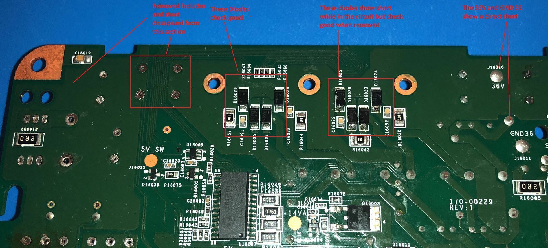
OK so I made a little more progress today. I removed the transformer and checked it out of the circuit. It checks out OK. I them removed the inductor near where I removed the caps and found that the short disappeared from that part of the circuit. I then started to look at the diodes that are in the picture below. The first set checked out OK while in the circuit but the second set shows a short. I then removed the diodes and checked them out of the circuit and they check out OK. So something else in that part of the circuit is shorted. Also the 36V and GND 36 test points show shorted.
Keep going 😉 You are getting there...
Have you felt any of the components getting warm? A short will typically be very warm somewhere and that will likely be the culprit.
Have you felt any of the components getting warm? A short will typically be very warm somewhere and that will likely be the culprit.
 +1
+1
I'm sorry, but I'm going to be stupid trying to find a suitable spare part.Can someone give me a link to a suitable spare part, e.g. at mouser or digikey?Many Thanks
Thank you! Yes, most likely it is really 2k.
No I haven’t plugged the board in since I have a bunch of components removed. I have been visually inspecting and checking with my meter however it is hard to see where the short is right now as there are a lot of components in that area. Also a lot of inductors.
Also there doesn’t seem to be anything visually to indicate component failure such a as burns or broken areas
Page 14 / 17
Reply
Enter your username or e-mail address. We'll send you an e-mail with instructions to reset your password.