The amp has no power. Is there an internal fuse for this unit?
Has anyone taken one apart?

Page 13 / 17
I have had this exact thing happen but on the 36V output filter. Where is this again on the board?
I definitely would fix that.
just extend the wire with a small piece of wire and insulate the connection with shrink tubing.
This fail means you prob either had a nick on that wire (winding) or you have a nick on the wire and a short down stream that made the nick show itself.
Either way fix the inductor and make sure nothing is shorted.
Dim bulb would help here.
See image...in red, on the dc output of the bridge.
Definitely looks like a nick in the wire.
I’ll report my status after I repair the inductor.
ok-that what interesting, after I thought I had removed the short from the inductor I soldered it back in mounted on the bottom for evaluation, I had a pigtail 5 amp fuse and brought it up slowly with my variac and the 5 amp fuse blew. I thought I was getting a very high resistance reading between the 2 windings where there should be none, I ended up fully unwrapping the inductor and rewrapping it, put a current meter in place of a the fuse in and slowly brought the variac voltage up,watching the current draw, stayed low and got the white light on front and made it up to full voltage with no issue...now to put the inductor back in correctly and try to connect...looking real good!
The way that coupled inductor is placed in the board layout always makes me scratch my head when troubleshooting that circuit. Is it possible when you put it back in and blew the fuse, that you had it soldered back in wrong? That would be easy to do.
Good to hear that you seem to have it on the mend!
I thought about that and is definitely a possibility, but I don’t want to think about it because then I fully unraveled an inductor when I didn’t need too! 
But, I did do a pretty good job of rewinding it .
It’s all setup and working!
I do have one heat sink clip I cant get back on, frustrating because I never needed to take it off, but there must be some special tool to spread this clip and get it over 2 transistor casings, I’ve read that it is a bear to get back on...and so far it is.
2 things about the heat sink clip.
- the Mosftet heat sink clip can EASILY bend the thin leads of the Mosfet, so be very careful. You wont know you bent the leads until the fuse blows. (the rectifier leads are much heavier and more resistant to bending) You may want to ohm out the 6 Mosfet pins after the heat sink is installed to make sure.
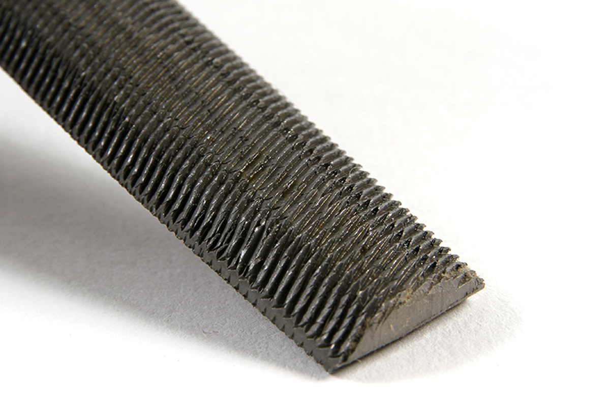
- Believe it or not i have used a butter knife handle to spread them open and very carefully drop them down into place. Also used a half round file. If you use something abstract let us know so we can add it to the lest. LOL

Hi!
I just bought 2 broken Sonos amps, one is completely dead and is waiting for me to disassemble it but before I do that I need some help with the 2nd one.
When plugging in the power cord I can see a white light from the led then it goes off.
the previous owner explained what happened before it died:
“It was late one Friday evening and suddenly I only heard sound from one of the channels (mono) and I tried to remove the speaker cables by turning the knobs, and that didn’t work so I tried even harder and then the amp died. Should I mention that I was a bit drunk? I realize now that you should pull the connectors. “
any clues? I have disassembled it and didn’t see and fried components.
Hey man,
No, that doesn’t tell you anything.
I would check for the bias voltages.
They must be there, that is how the led is coming on.
maybe they only come up for a short time.
Look for missing voltages. Be careful. High voltages at the input.
Hey man,
No, that doesn’t tell you anything.
I would check for the bias voltages.
They must be there, that is how the led is coming on.
maybe they only come up for a short time.
Look for missing voltages. Be careful. High voltages at the input.
Thank you, Gruv2ths! I’ll try to have a look again for any damages and then try to measure. I have been doing a lot of repair when it comes to retro video games but that’s always 12v or less so I am a bit nervous when it comes to 230v.
I figured to grab my other broken Sonos amp from storage and I didn’t notice it when I bought it but it looks like the previous owner already opened id.
The fuse was open, and the solder points looks very shady, so either he replaced the fuse or only tried doing so.
I had a pair of fuses lying around so I quickly replaced it, reassembled everything and once I plugged in the power chord my lights went out and I could smell electronic burn  xD
xD
Is this a case where it’s appropriate to use a bulb? A friend of mine told me to hook up a bench power supply (with very low voltage) and trace the signal from there.
All other components looked good, from the look of it.
BTW How can I figure out that the 110v/230v switch is ok and not shorted?
It’s been a while for me, but I’m revisiting some old dead units. The first one I picked up has already stumped me, and I know it shouldn’t, as the problem seems like it should be a slam dunk to fix.
ZP120 with no power. With a dim bulb, it lights then fades. When I look inside, the main rectifier is fine. I have 162V on VMID (good), and 162V on VPRI (BAD). I replaced the shottkeys, and the diodes and capacitors all seem ok. What am I missing??
Hey Tim, You mentioned that you replaced the caps, does that include the big ol’ pair of electrolytics?
Also the diode bridge (4 pin part that clips to the chassis). Are those new?
Thanks for replying gruv.
I had another look today. I removed the rectifier and checked it out of circuit - it was fine. I removed the three caps near the mosfets - they were fine. I removed and replaced the two mosfets with new ones. I checked the two large electrolytics in circuit and they seemed fine.
Then I started poking around and was trying to reverse engineer the circuit. I couldn’t see a lot of the components well, and not all the traces either, given how tight some components were. I ended up removing the choke just downstream of the rectifier. I held the board up to some bright light and could finally see where the positive trace was running. It was leading back to Vpri via a varistor. BUT… the trace was dead! I couldn’t see the trace as it was under some paint, but this unit was water damaged and my guess is that it was probably rusted out.
So, I put everything back in (the choke was a pain), ran a jumper where that trace should be… and now I had 320 on Vpri.
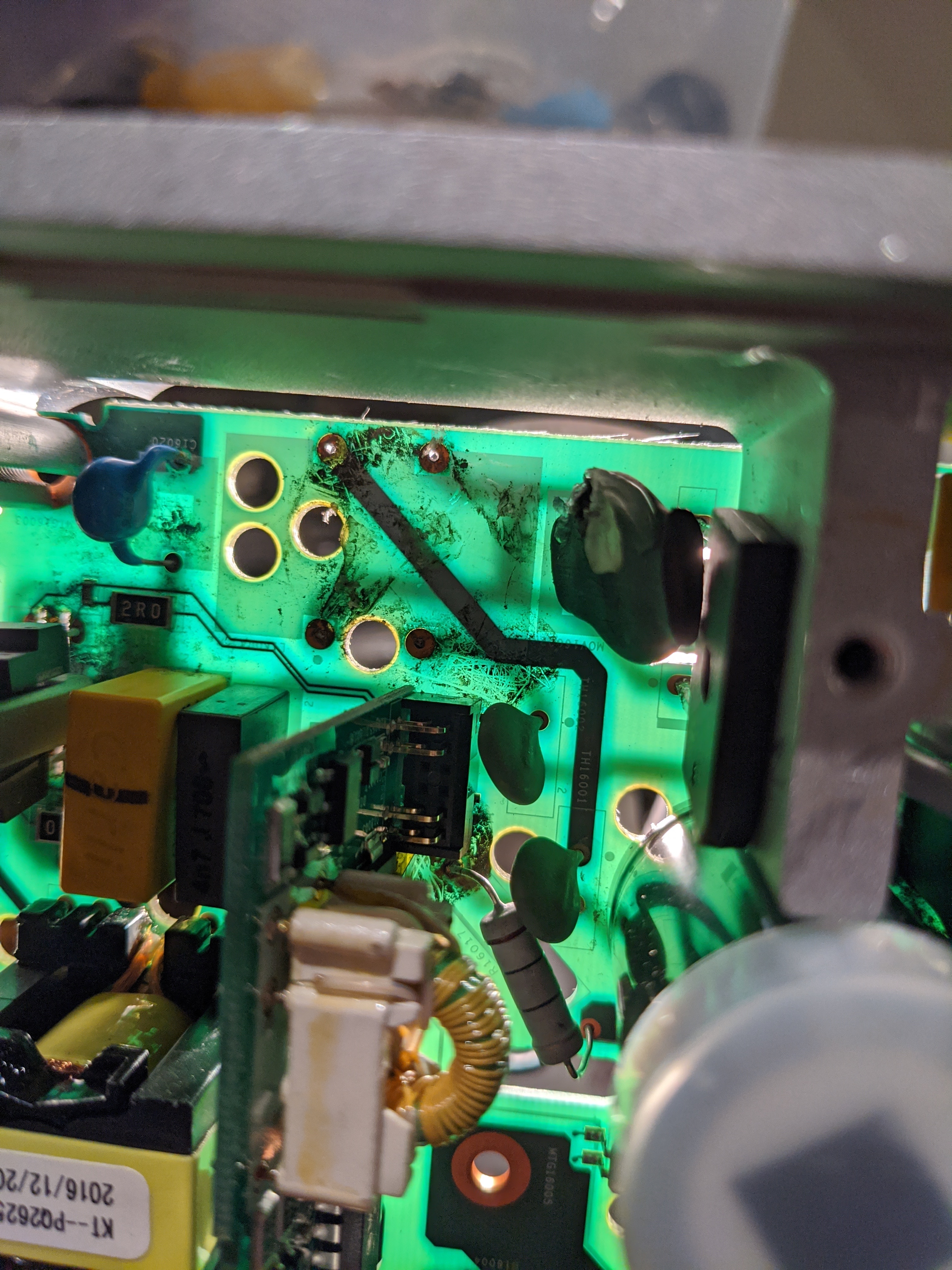
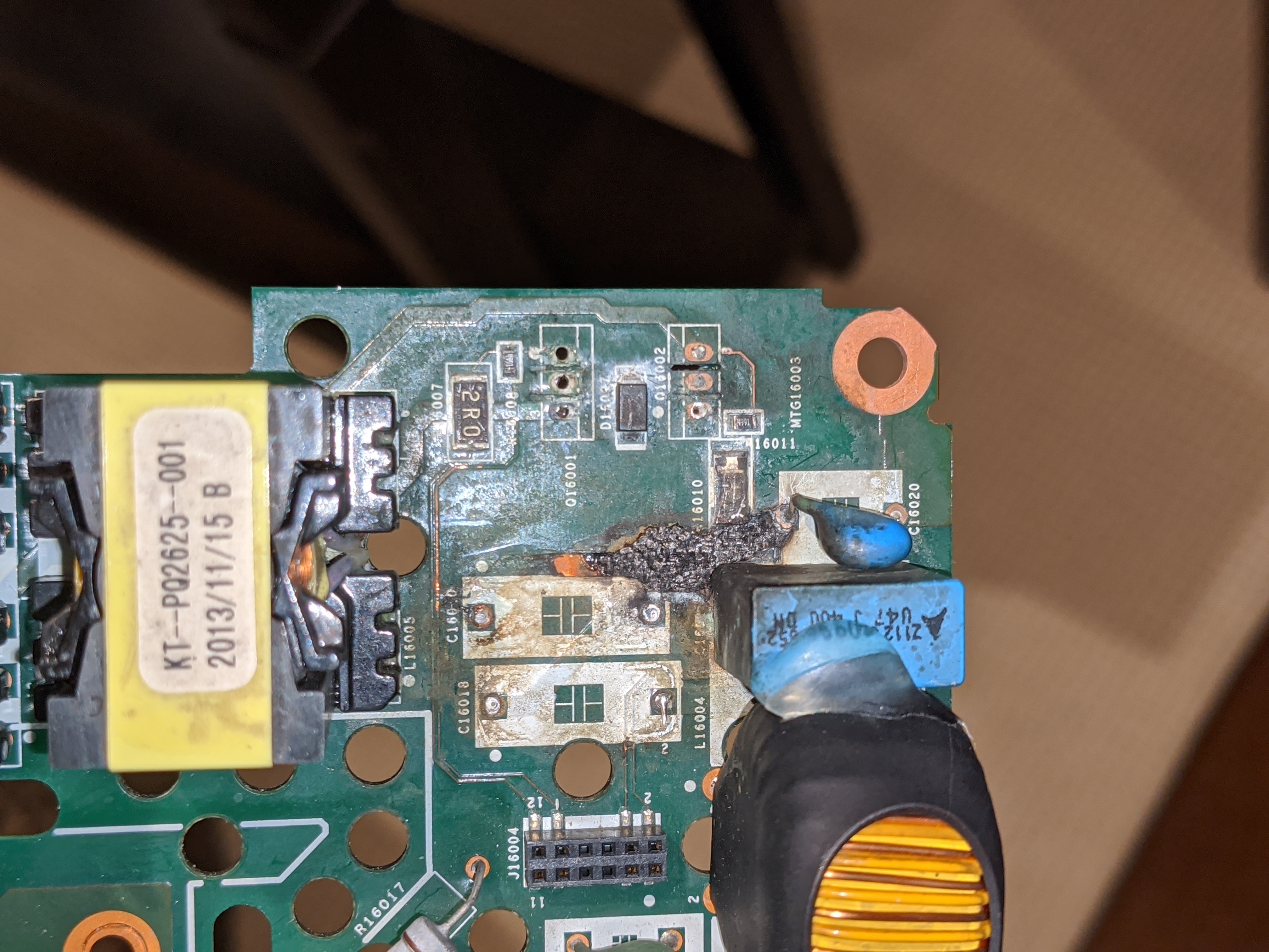
Unfortunately I don't have any biases on the secondary. It looks like more damaged parts - probably the oscillator. Well… at least I am making some progress. Here’s a picture of the likely problem I have to fix now…
Wow, that shot with the light behind the PCB was amazing! Well done!
I forgot about that coupled inductor. That guy conducts ALL of the primary power. One small nick in that mag wire will cause the inductor to blow open and no voltaje, in a very ambiguous way.
So given where you are, primary power restored, i would get a datasheet for the bias converter PWM and get to work. In this thread there are some nice test point references to show you what you should get with a working unit. Take a good look around the PWM pins on the bottom for corrosion.
Pro-tip: the bias converter is a very standard flyback converter. If you google flyback converter you will get something similar to what you have in the AMP. Look closely in the primary winding snubber. Also check the 10ohm high wattage through hole resistor, it provides power to the transformer primary.
, but this unit was water damaged and my guess is that it was probably rusted out.
At this point I recommend a thorough cleaning of everything. Residual from that liquid can cause future trouble. Soda spills are some of the worst because the residue takes on water from the atmosphere and forms acids that can cause unwanted conduction paths and eventual trace and component failure.
Just an update, as I am grateful for the assistance provided here and feel I owe it to gruv and the thread...
I have 4 units that I was hoping to salvage, and 1 that I was using for parts. The one I found the broken trace on (described above) turned out to have no continuity on the primary side of the transformer. My guess is that the leads are rusted out on it, and I’ll have to remove it to have any hope of getting it working. That’s worth trying, but another day given it’s a pretty daunting task.
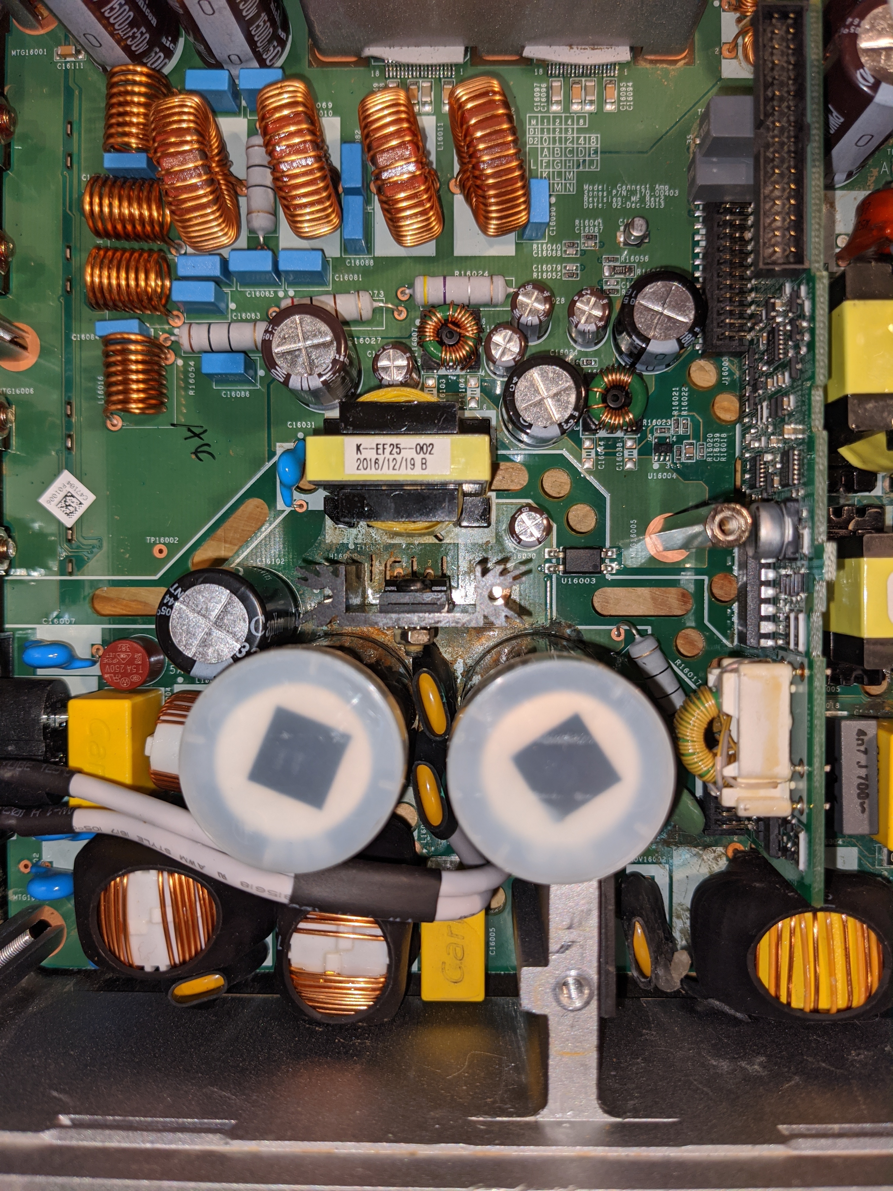
The other 3 units that I have that I thought I might be able to repair… On the first, I found I had no connection on the secondary side of the transformer between the two ground points, as well as a bad trace from the big 10 ohm resistor to the coil. On the second one, it was a bad amp. Both of those units now boot but then go to flashing white/orange. I suspect I need to replace the ST508 amps on them. The third one has an ok primary but nothing on the secondary...I haven’t debugged that yet. I also have another bad main board. It has huge burnt traces on the primary side… I had previously assumed this was toast, but think now that it may be fixable. Maybe I’m wrong, but I have some newfound confidence, given what I’ve learned about the circuit in the last couple of days (image below, with some nearby components removed).
I also have the 5 logic boards from these. Two of them work and 3 don’t. One is very obviously water damaged and the other 2 have no obvious issues.
Buzz.. thanks for the tip. I will give everything a clean before considering these ‘fixed’...but I obviously have a lot of other work to do first!
If I see a PC board that has obviously been the victim of a liquid spill, I’ll clean the board before applying power.
And that burned trace is the victim of another, very significant drama. I would track that down before applying power again.
A very thorough visual inspection is worth many hours of troubleshooting.
Recently, a friend brought me a product that was not working. I couldn’t test it because I didn’t have the power supply, but I disassembled the unit and discovered that it had been the victim of a liquid spill. A few traces had obviously been dissolved by remnants of the spill. I repaired the traces and sent the unit home without ever turning it ON. It worked at home.
Hey all. Incredible to see this thread is still alive.
Hoping I can squeeze out some more information regarding the flashing orange light.
I've got a dead zp120 from liquid damage (almost) back up and running.. It had a blown fuse, both N-channel MOSFETs and both shottkey diodes (the 2 pairs under those piece of trash clips) were dead shorts as well as a totally burnt trace and pad on q16001 (MOSFET). Replaced the 5 components, repaired the trace and everything powers up!.
All. voltages seem good EXCEPT I never get 36V between GND36 and 36V it sits at ~15v. When the volume is turned from 0 to anything I get a blip of sound (quick drop to 13-14V) and then orange flashing light, with the volume bar jumping back to ~15%.
I suspected the 14 pin IC on the logic board gruv2ths mentioned solved his similar issue. I swapped the entire logic board with a known good one and same thing.
Where is this 36V supposed to come from? Do I have a switching issue? voltage issue? OR are the amp chips gone? Need a push in the right direction to identify what's failing.
The 36V only becomes active above a certain volume threshold. I found some sonos patent information a while back - this approach is what allows the unit to be low power until higher power is needed (ie when it is actually amplifying), and this is why leaving them on continuously doesn’t create a lot of heat or use a lot of power.
So the 15V you get at the 36V point is ‘normal’ when the device is in standby or at low volume, but when you hit play or turn up the volume then the 36V should come alive and the 36V point should read 36V.
I believe that the 14 pin logic chip is what controls the on/off status of the 36V. That is located on the top logic board. I recall gruv2ths saying somewhere that some of the 36V control circuitry (perhaps a recitifier) is on the riser board. You might try to swap that riser to a known good one and see if your problem goes away or not. Once you have the top logic board removed, the riser just pulls straight up.
I think that if the amp chips are gone, then they could be causing a short that is affecting the 36V. Hopefully that’s not the problem.
Thanks Tim. When I tried the other logic board, I didn't swap the riser board! will have to try that, wasn't aware of any control circuitry there.
I'm leaning towards the amp chips, but would really like to know if they were shorted would the problem present itself as it is?
Should the 36V be available anywhere on the board while in standby?
If I remove the amp chips should the 36v present itself once the volume is turned up?
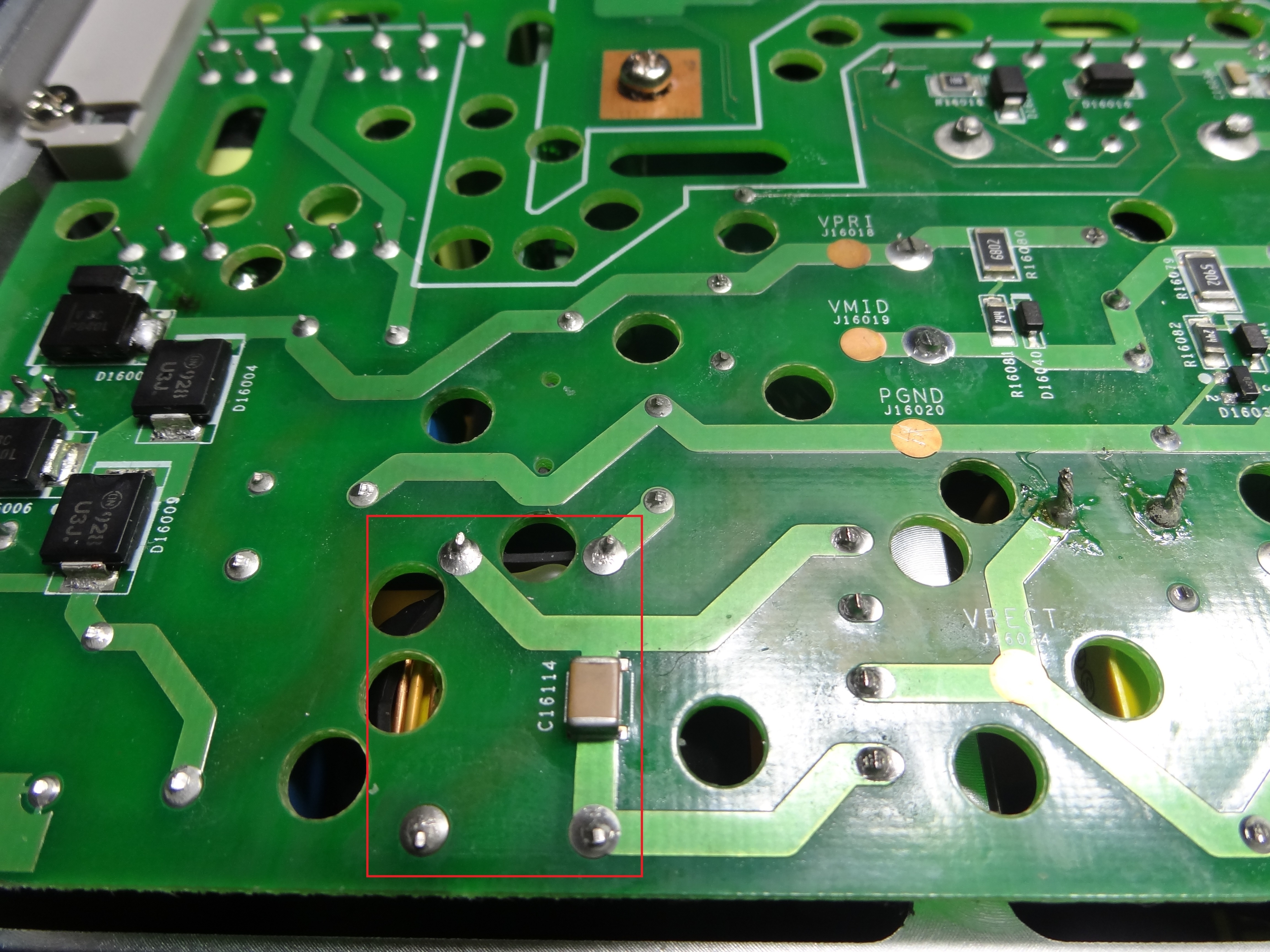
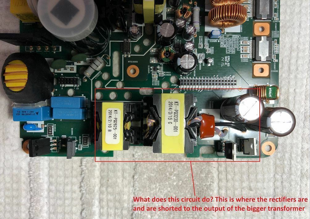
This photo is from 2 years ago from this thread from a user that I don't think got to the bottom of his issue. The hilighted area as I understand is the 36v supply?
Thanks Tim. When I tried the other logic board, I didn't swap the riser board! will have to try that, wasn't aware of any control circuitry there.
I'm leaning towards the amp chips, but would really like to know if they were shorted would the problem present itself as it is?
Should the 36V be available anywhere on the board while in standby?
If I remove the amp chips should the 36v present itself once the volume is turned up?
This photo is from 2 years ago from this thread from a user that I don't think got to the bottom of his issue. The hilighted area as I understand is the 36v supply?
It’s hard to know what symptoms a blown chip would cause. I once had blown amp chips that went in such a way that they lost some of their pins in the process -- literally blown off. In something like that, the traces could be damaged, it could cause shorts elsewhere… It’s just too hard to know for sure what to expect.
That section is the 36v supply. If you are familiar with the primary side voltages, the power path from input 120/240v is rectified and passed through a dual inductor and 320v dc is produced which is available on pin 5 of the primary side of the tarnsformer. Somewhere around the mosfets that are part of the doubling circuit that generates 320v, the circuit apparently branches and feeds into the 36v supply section you identified (I’ve never looked at where this happens in the zp120).
I just looked at that section on a board… it does look fairly straightforward. What I mean by that is that it should be possible to check many of the components. Bad diodes, capacitors or even open windings can all be looked for in circuit. The 3 pin devices that look like transistors are actually dual diodes and those diodes can be checked too (use diode test between the middle leg and each of the outer ones).
I have some zp120 devices that have the same symptoms you describe -- i just haven’t invested time in looking much further at this point. I have fixed a lot of the older zp100 devices, and they had similar voltages. In those, the 36v would be unavailable when in standby and i think the zp120 would be the same.
Please post back here is you find anything (good or bad).
ITS THE DAMN RISER BOARD! I'm so happy, and at the same time mad at myself for not trying that when I tried a known good logic board.
with the repaired power supply, known good riser and existing (from the bad unit) logic board, I got my 36V and sound.
Now to dig and compare what's wrong with the riser board, or buy one of they're available.
Wow -- that’s excellent to hear.
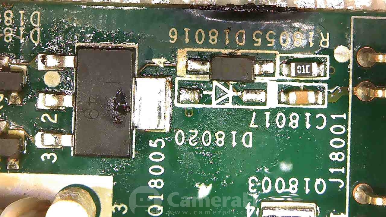
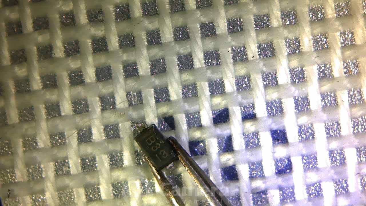
This is right above the smaller connector of the riser board (j18001). I found a short on pins 2/3 of Q18005 removed it and eventually traced it to a shorted D18020 right in front of it. D18020 is labeled D3 with a sideways 13, which I think is the date code. I believe it's a zener diode but not sure. Will try a few things and report back.
That was it! I replaced the shorted diode with a 1n4148 as that's all I had on hand. No more orange light and she sings!
I have to thank everyone that participated in this thread, wouldn't have gotten her working without your help.
Enter your E-mail address. We'll send you an e-mail with instructions to reset your password.