The amp has no power. Is there an internal fuse for this unit?
Has anyone taken one apart?

Page 16 / 17

OK I pulled the transformer off the board and ran jumpers to the primary side. I then plugged in the amp and measure the secondary and still reading 0 VAC. I am also hearing a clicking sound coming from the main board while the transformer is removed and the amp powered on. Not sure what that is.
Ok.... this is revealing. This would appear that your transformer is bad. The AC through the transformer should certainly give you output voltage on the secondary...
Just to verify... you are measuring the output of the transformer... NOT the board?
gruv2ths - What do you think?
Just to verify... you are measuring the output of the transformer... NOT the board?
gruv2ths - What do you think?
Well done!
I put mine back into the shell to clear it off my desk. Forgot the volume/mute buttons, so I did that twice, including those F****** clips!
And of course the orange light is back.
sigh
Look at this:
https://www.wikihow.com/Test-a-Transformer
The shaper looks good since you have AC on the inputs. You show 0v outputs. From this doc, it appears you may have found your problem. Your transformer looks bad.
https://www.wikihow.com/Test-a-Transformer
The shaper looks good since you have AC on the inputs. You show 0v outputs. From this doc, it appears you may have found your problem. Your transformer looks bad.
I'll add this in there as well: http://www.electronicrepairguide.com/testing-transformer.html
Under Number 1 - "Switch on the equipment and measure the input and output voltage of the transformer with either an analog or digital meter. If there are no voltage or lower voltage then it suppose to be, the transformer need replacement. I personally liked this method because you are testing the transformer under full operating voltage which is very accurate. "
Under Number 1 - "Switch on the equipment and measure the input and output voltage of the transformer with either an analog or digital meter. If there are no voltage or lower voltage then it suppose to be, the transformer need replacement. I personally liked this method because you are testing the transformer under full operating voltage which is very accurate. "
Be warned once again RE those terribly designed stubborn clips. I saw gruvs post about Bending the pins on the MOSFETs when putting the clips back on. When I reassembled, I didn't use the little condoms Sonos included and just had the clip on the metal of the shottkey diodes (D16005). guess that was shorting the 36V line again. back to fully operational.

Guys, this power supply is generating the proper voltages. He is getting his 3.3, 8ish and 15.
I suspect it’s a idiosyncrasie of the meter. I bet a scope will show you what is at the secondary leads better. When I am back at my bench I will get some scope plots and show them here.
I suspect it’s a idiosyncrasie of the meter. I bet a scope will show you what is at the secondary leads better. When I am back at my bench I will get some scope plots and show them here.
My Dmm shows 0V as well. The scope says otherwise. So look past the diodes for the output of the converter. You’ll notice that from each non-RTN transformer pin there is a trace that connects the rectifier diode. Look at the cathodes of those diodes for the positive outputs.
The scope never lies 😉 Interestingly, I used a Fluke 87 and it got the voltages...
Nice scope....I have a Rigol DS1104Z. They are invaluable.
Nice scope....I have a Rigol DS1104Z. They are invaluable.
Mine doesn’t have the True RMS feature, and that may be why?
Thanks gruv2ths. That makes me feel better about those voltages. I received the new STA508 last week and planning on replacing it this week. After I replace it, I will try powering on the amp again and cross my fingers.
Ando, did you get the voltages coming from the riser board to the logic board?
If you mean the 1.5V from the buck converter, yes I am getting that. Here is the post from a while ago: https://en.community.sonos.com/advanced-setups-229000/repair-zp120-17442/index5.html#post16189903
No I meant the voltages at the riser board connector with the logic board removed.
Ah I see. Sorry I have not checked for any voltages here before. Where should I check and what values should I expect?
The idea is to make sure your non functioning logic board is getting the bias it is expecting. We can compare what you read to what my working riser card is delivering. So check all the riser card output pins to chassis.
Hey gruv2ths. Sorry I haven't been on in a while. Work has been nuts and getting ready for vacation. I actually screwed up the other day when I was taking some voltage measurements and accidentally touched 2 pins on the PWM when it was powered on. I saw a small spark but no smell/smoke, however now I do not have the bias voltages on the secondary any more. I checked the fuse hoping it was just that but no go. I am really not sure I want to keep going on this as I am not sure I can bring this amp back to life. Have you made any progress with the other amps that you were troubleshooting?
Hey Ando,
No luck but no time to mess with them.
Check the 10 ohm resistor. It is axle leaded and 2 W and on top of the board.
If it reads 10 ohms then replace the PWM again.
That SHOULD get you back in the road.
No luck but no time to mess with them.
Check the 10 ohm resistor. It is axle leaded and 2 W and on top of the board.
If it reads 10 ohms then replace the PWM again.
That SHOULD get you back in the road.

I hope this thread is not dead.
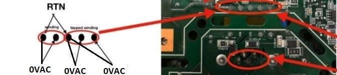
I just got a ZP120 that can't power on. I have tracked down the main power transformer is dead: the primary windings are broken: from 1(RTN) to 2 is OL, 3(RTN) to 4 is 1.8ohm (this is the only good one), 3 to 5 is OL. Due to this problem, all secondary outputs are 0V.
I am wondering if the transformer part can be purchased anywhere. Otherwise I am open to other alternative Solutions like external power supplies?
Did you remove the transformer and check it? The only way to really know is to test it off the board. Transformers are tough to go bad...it takes a lot to blow one.
If you did test it off board, there usually is a number on the transformer. You may be able to go to Alibaba and search for the number/MFR to try to get a match. The other option is to get the size and windings (i.e. the specs) and try to get a replacement. If its the main Xformer, then that can be fairly standard as its a step down to generic voltages. You may be able to determine the windings from the front side voltages to the secondaries based on the output voltage (i.e. 120v to 3.3v == 120/3.3 ~ 36:1 winding, so on and so forth). You can also reach out to the MFRs and state the input/output voltages, and they can usually find one for you. You would need to give them the size... maybe some pics, etc.
Final option is look for a ZP120 on eBay that is dead as a door nail and try to get it for $20 for parts.
Hey all. Incredible to see this thread is still alive.
Hoping I can squeeze out some more information regarding the flashing orange light.
I've got a dead zp120 from liquid damage (almost) back up and running.. It had a blown fuse, both N-channel MOSFETs and both shottkey diodes (the 2 pairs under those piece of trash clips) were dead shorts as well as a totally burnt trace and pad on q16001 (MOSFET). Replaced the 5 components, repaired the trace and everything powers up!.
All. voltages seem good EXCEPT I never get 36V between GND36 and 36V it sits at ~15v. When the volume is turned from 0 to anything I get a blip of sound (quick drop to 13-14V) and then orange flashing light, with the volume bar jumping back to ~15%.
I suspected the 14 pin IC on the logic board gruv2ths mentioned solved his similar issue. I swapped the entire logic board with a known good one and same thing.
Where is this 36V supposed to come from? Do I have a switching issue? voltage issue? OR are the amp chips gone? Need a push in the right direction to identify what's failing.
I just got a ZP120 that can't power on. I have tracked down the main power transformer is dead: the primary windings are broken: from 1(RTN) to 2 is OL, 3(RTN) to 4 is 1.8ohm (this is the only good one), 3 to 5 is OL. Due to this problem, all secondary outputs are 0V.
I am wondering if the transformer part can be purchased anywhere. Otherwise I am open to other alternative Solutions like external power supplies?
Not dead... nobody has had anything broken or came back :-)
Did you test that transformer off board? That's critical as being on board can give you different numbers depending on the circuit or if something is blown/shorted. Transformers do not blow very often and are fairly stable. Take a really good look at it off board and see if you see any evidence of charred marks or something if it registers bad. If it registers good, then its something else and you will need to do a bit more detective work.
If you are 100% sure its the transformer, you usually can find a number or code on it. You can search for that on Alibaba or reach out to some of the Chinese transformer manufacturers and see if they can find it. If not, you have the input and output voltages, so you can can give that to them as well to see if they can get a match. You can generally determine the winding ratio by dividing the input by the output... i.e. 120v to 3.3v = 120/33 ~ 36:1 winding for step down. You will need to calculate that for each input/output. You could also unwind it yourself and get an accurate winding count. Since its the main transformer, its a reasonable chance that its standard. If you can get the MFR, you can always contact them and they should have them on hand. However, there is a chance its a custom wind, and you would need to reverse engineer those windings yourself.
The last possibility is check eBay for a seriously bad ZP120 and see if you can grab it for $20 and just pull the transformer out of there.
Hi m0untainman,
Thank you so much for the detail explanation, That helps a lot.
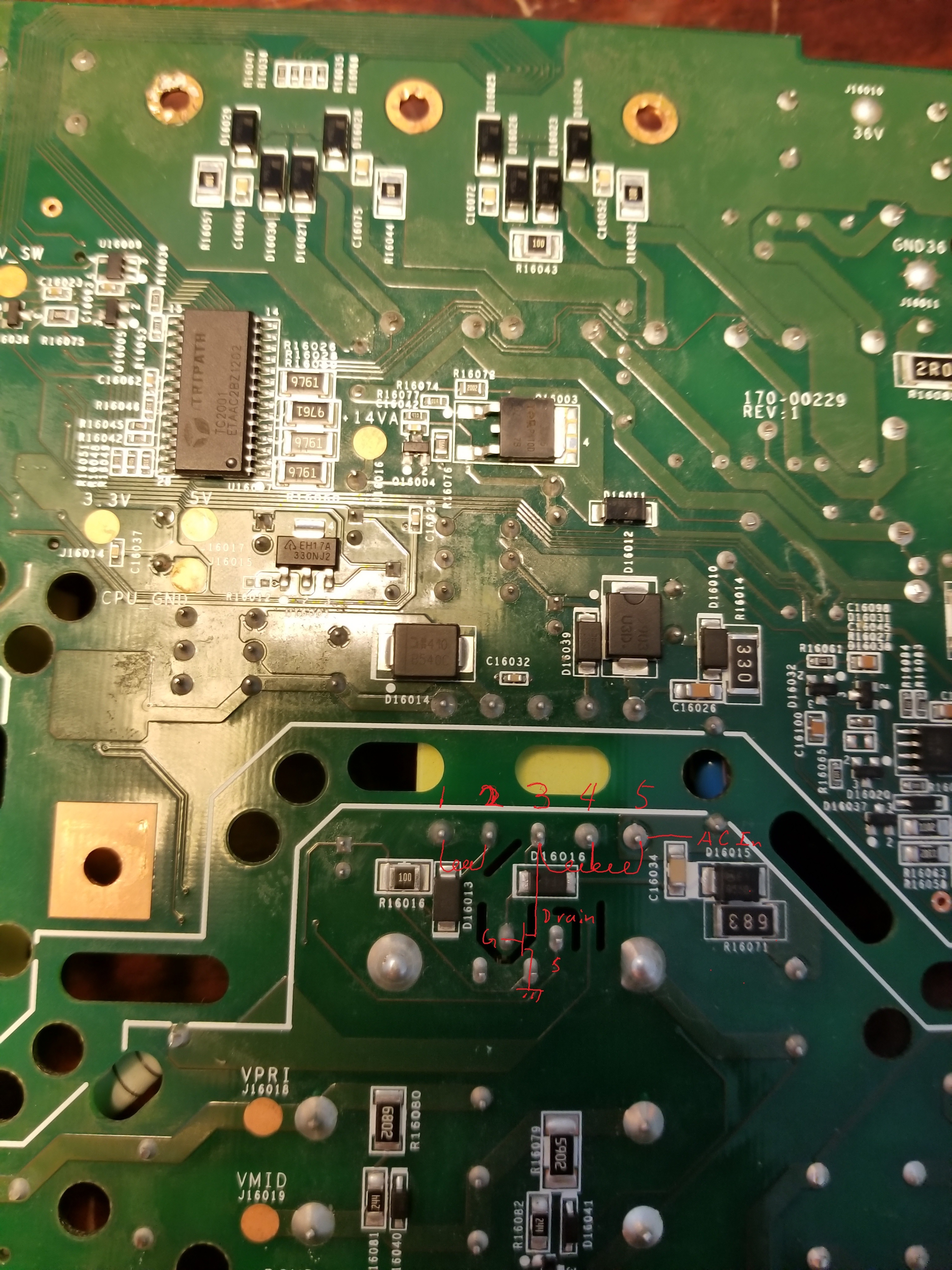
I did all the measurement with the transformer on the board and I understand your point on other components' impact for the measurement (I have an EE background doing chip design and debug works :)). However for this specific case, I am only checking the resistance of the transformer coil resistance. The picture is my understanding of this circuit:
the resistance between 1 and 2 is OL with with FLUKE 179 DVM, between 3 and 4 is 1.8ohm which looks for me. but either 3 and 5 or 4 and 5 are OL which to me means the coil is broken somewhere between 4 and 5 inside the transformer, other parallel circuit would make the resistance smaller but not bigger/bigger.
with powered on, I got about 340V DC voltage on pin 5. but only stable ~1.5V from either 3 or 4. I have checked the PWM chip: the feedback (oscillating), VCC all looked fine. there is just no current flow from 5 to the PWM drain to generate voltage on the secondary coils so they all stay at 0V (I am expecting to see 3.3v, 5V, ~14V). I am not sure what 1-2 are connected to.
Any inputs will be very helpful.
Thanks,
-Tao
Thank you so much for the detail explanation, That helps a lot.
I did all the measurement with the transformer on the board and I understand your point on other components' impact for the measurement (I have an EE background doing chip design and debug works :)). However for this specific case, I am only checking the resistance of the transformer coil resistance. The picture is my understanding of this circuit:
the resistance between 1 and 2 is OL with with FLUKE 179 DVM, between 3 and 4 is 1.8ohm which looks for me. but either 3 and 5 or 4 and 5 are OL which to me means the coil is broken somewhere between 4 and 5 inside the transformer, other parallel circuit would make the resistance smaller but not bigger/bigger.
with powered on, I got about 340V DC voltage on pin 5. but only stable ~1.5V from either 3 or 4. I have checked the PWM chip: the feedback (oscillating), VCC all looked fine. there is just no current flow from 5 to the PWM drain to generate voltage on the secondary coils so they all stay at 0V (I am expecting to see 3.3v, 5V, ~14V). I am not sure what 1-2 are connected to.
Any inputs will be very helpful.
Thanks,
-Tao

So I gave up on trying to solve the problem with the existing circuit. I ended up replacing the 240k resistor at R16082 with a resistor divider network. I used 15k+4.7k+100k, with one leg of the 100k tied to the 59k resistor, and one leg of the 15k tied to GND. The junction between the 4.7k and 100k resistor should then end at about 18V (ie approx (15+4.7)/(15+4.7+100+59)*sqrt(2)*115). I tied that to the VCC input of the PWM. I used ¼ watt resistors for all three of the resistors. The lower resistance at R16082 (~120k instead of 240k) drops the voltage at the junction between R16079 and R16082 to 109V. The current flowing through the resistor divider is 0.9 milli-amp when the PWM draws no power, and <1.1mA when it acts as a short circuit. As a result, power dissipation for the largest resistor (100k) in the resistor network is under 1/10 watt (making the ¼ watt resistors overkill)
The circuit works fine now. I didn’t time it, but it may take a couple of seconds longer to boot up. There is a 100uF capacitor on the PWM VCC, and that needs to charge up before the PWM VCC line exceeds the 16V it needs to start oscillating. Otherwise, there is no issues with the circuit.
Maybe this only works so well since the PWM chip is tolerant of voltage fluctuations on its input (it needs to start up with >16V, but then will operate with any voltage from 8-24V). The original circuit may have provided a more stable VCC, but it’s just not needed given there is only one chip drawing less than a milliamp.
Look really closely at that transformer for a burn mark or something to validate that the transformer may be bad. Since you have an EE background I am sure you know it takes something super nasty to blow a transformer and its fairly rare to take those out. I would also check the solder joints on it as well as the connectors leading into the transformer. Its possible one of them has a bad solder joint or the pins connected to the transformer wires got wonky and may just need to be re-seated. Reflow the solder on the pins and see if you get some continuity. Try testing the continuity from the other side of the board on the transformer pins...that way you can wiggle them a bit. This is sort of why I recommended to just remove it it and test it out of circuit as you will know really quickly if its bad or not, as opposed to a poor solder joint.
Even though the PWM is oscillating... double check its output voltages. That part is the most sensitive of the entire board and its been really easy to blow those with a simple short.
Even though the PWM is oscillating... double check its output voltages. That part is the most sensitive of the entire board and its been really easy to blow those with a simple short.
Page 16 / 17
Reply
Enter your username or e-mail address. We'll send you an e-mail with instructions to reset your password.