The amp has no power. Is there an internal fuse for this unit?
Has anyone taken one apart?

Page 15 / 17

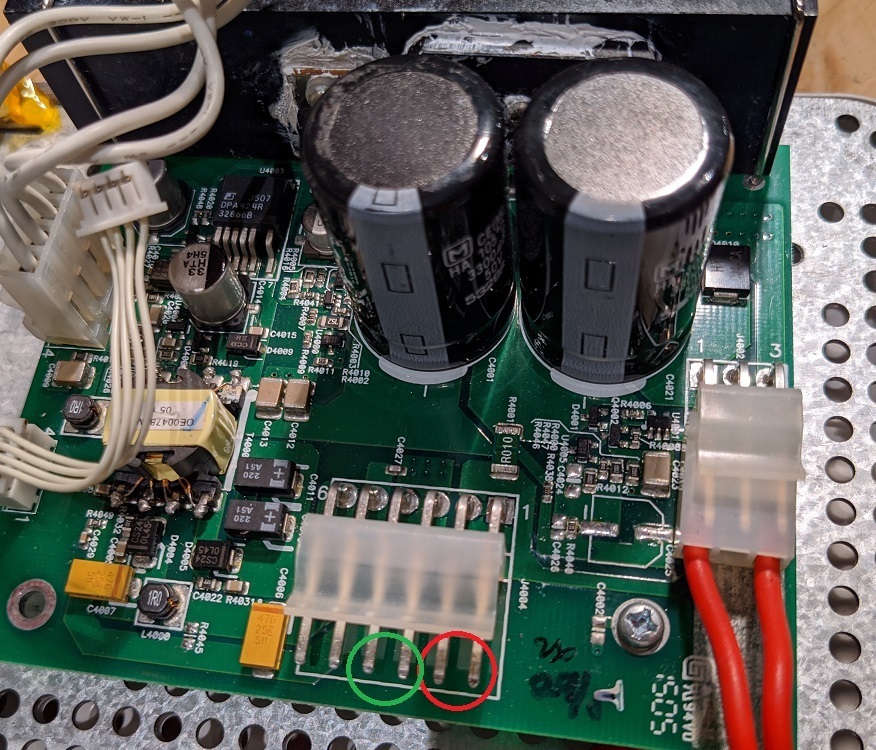
In the meantime, are there test points where I can check for this 36VDC and/or other voltages to see if my amp section is at least attempting to engage when I hit play?
I’ve forgotten where the switching on occurs in the unit. However, I did have a power board lying around and took some measurements. You should find 36V between the labelled pins.

Yes, the inductors may appear to as shorts if they are used with dual windings for filtering... same concept as the transformer. Also, chances are that your transformers and inductors are ok. Those are really really hard to blow. Concentrate on diodes/caps/resistors/ICs.
Small tip: If your components look good... put them back in. Its easy to lose the correct ones. If you want to leave off inductors and transformers, then thats fine.
Second small tip: Test what you can on-board/in-circuit. If it looks good, you can likely not worry about removing it. If it looks bad, then you can do a secondary test after removing it. That may prevent having to remove a lot.
Hello, im from Germany and need your Help.
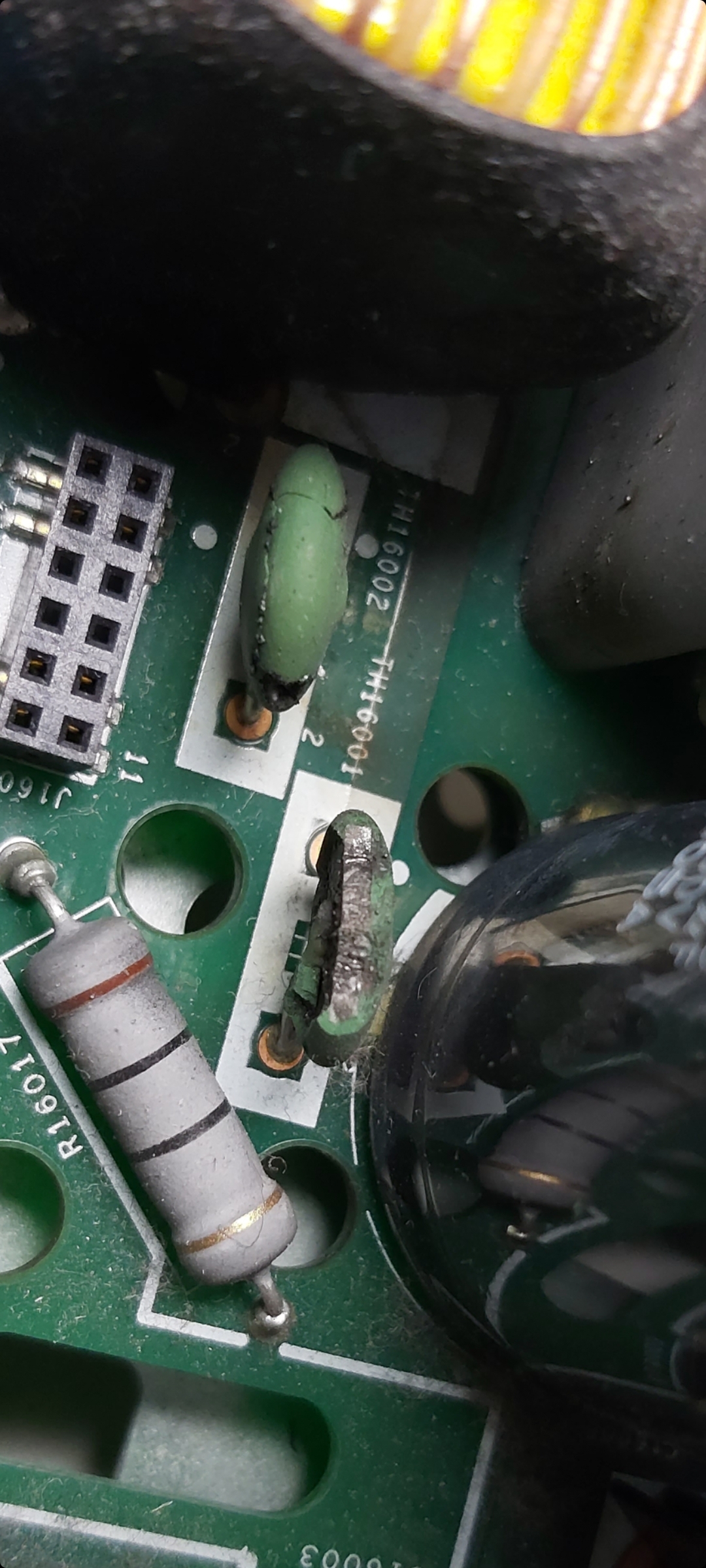
These two capacitors are defective. do you know the data for these?
TH16001 and TH16002.
Thank You
Max
Hi guys, I own a connect amp that was plugged (by previous owner) in to 220v when switch was on 110 v.
I replaced the fuse, replaced the TVR14241 (mov) and i noticed that the TH16001 also cracked. I could not source the Sck054 needed to replace this part in my local electronics store, so I hardwired it for now, and everything works perfectly.
Questions are:
- with normal use (no power surge, no wrong voltage), will the unit get damaged if I keep it like that?
- is th16001 used in 220v setup, or is it for 110v only, and th16002 for 220v?
If it will Increase the lifespan of the unit, i will order the SCk054 online.
Thanks for this super interesting group discussion, got me already quite far!
The thermistors here are NTC (negative temperature co-efficient). These will have a higher resistance when cold than once they warm up. I’m not an expert but I think that the purpose is to limit the inrush current when the device is first plugged in. These are used in most sonos devices that drive speakers. Each of these has large capacitors that charge up, and which will draw large amounts of current quickly without the thermistors. You may notice your lights dim a bit when you plug in a device without them. I notice this dimming with the ZP120 Connect:AMP devices, and that’s with the thermistors working!
The thermistors are active in both 110v and 220v devices.
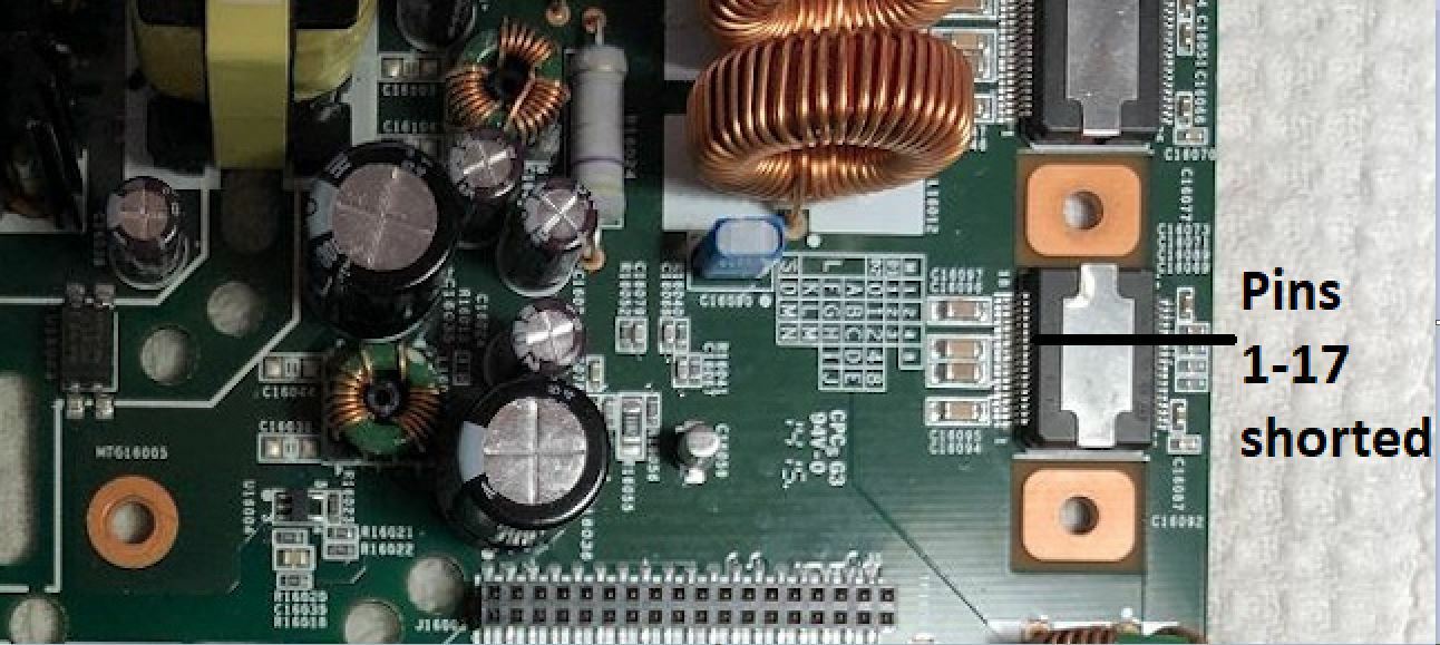
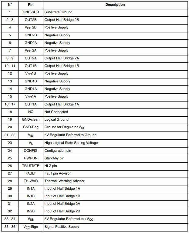
A little more investigation last night is showing that pins 1-17 on the power half bridge are shorted together. I am not sure if the chip itself is bad or something else in the circuit. I will try to do some more digging tonight. Again a visual inspection of the bridge shows absolutely no damage so I find myself lost again :-(
Hi, can you sketch the circuit around these diodes out for me?
I would imagine if the other one gives .68v, then it is probably a general purpose silicone diode.
As I say, sketch it out and I'll have a think.
Kind Regards,
Andy
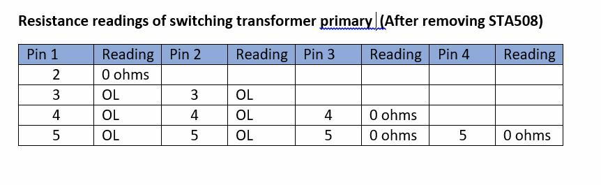
Update: removed almost all diodes from underside op primary side. Theyre all Good. Something I noticed is that all the 5 points of this winding in the secondary side are shorted together, is this right?
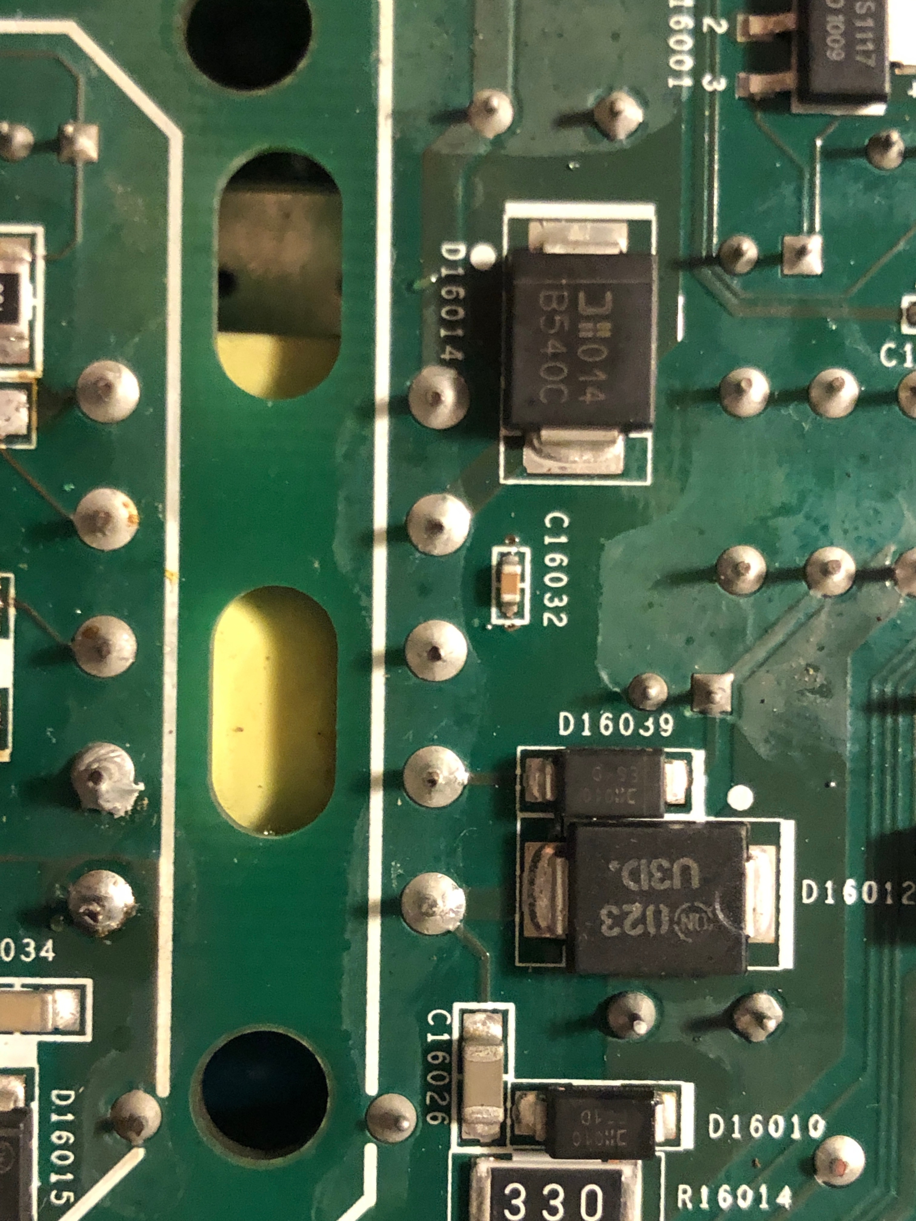
The secondary winding has two separate coils. The first is across three pins with a centre tap. Within each coil (the first 3, or the second two pins), you should measure a very tiny resistance (under 1 ohm) between the pins -- this is normal for a transformer. The short between the two coils is not normal. You may have a short between the two secondary coils, or it could be ‘downstream’ of that.
I’ve fixed dozens of these devices and haven’t seen this particular problem before. You can try to remove the transformer and see if the dim bulb stays bright. If it does then the transformer is probably not the problem. Be warned though… Getting that transformer out and then re-installed is a pain to do.
Well I have checked everything I can think of in or near the part of the circuit that has the short. Seems like all caps and resistors check out OK. My guess is that the STA508 amp chip may be shorted and that is what is causing the failure. I cannot think of anything else unless you guys can.
Thanks gruv2ths - I did try removing the STA508 with Chip Quick but I could not get it off for some reason. A friend of mine has some better tools so I am going to take it to him to see if he can remove it. Also do you have a link for that eBay seller for the STA508? The only one I found is from China and the ETA is about 2-3 weeks. Would like to get it sooner if possible.
As for any other visible sign of a short, there does not seem to be anything. I have closely looked at all the caps, inductors and resistors and they look absolutely perfect. I am hoping that the STA508 is the root cause of the fail and replacing it will bring this baby to life!
As for any other visible sign of a short, there does not seem to be anything. I have closely looked at all the caps, inductors and resistors and they look absolutely perfect. I am hoping that the STA508 is the root cause of the fail and replacing it will bring this baby to life!

Thanks, will check it out!
I put the amp back together and tried powering on (with the dim bulb tester inline) and no joy. No white light on the front panel. Some good and bad news:
The Good:
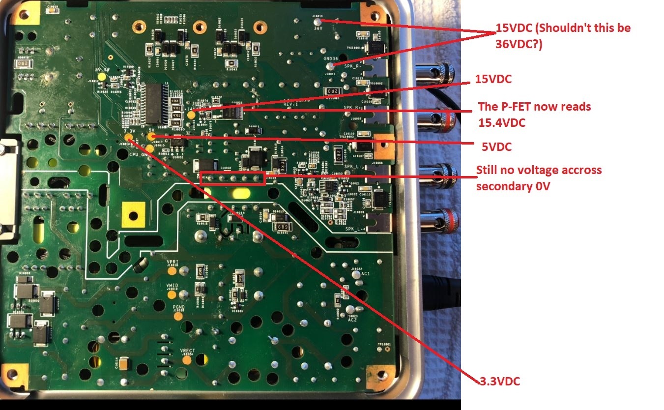
For the first time, I now have 15.4 volts on the P-FET.
In addition all of the test points around the P-FET show their proper voltages
The Bad:
I still do not have voltage readings on the secondary output of the switching transformer that is controlled by the PWM
Not getting the flashing whit LED which indicates the amp is booting
The Unknown:
The 36V and GND 36V test points only read 15VDC. This seems strange.
Could the PWM be causing the 0V readings across the secondary?
The Good:
For the first time, I now have 15.4 volts on the P-FET.
In addition all of the test points around the P-FET show their proper voltages
The Bad:
I still do not have voltage readings on the secondary output of the switching transformer that is controlled by the PWM
Not getting the flashing whit LED which indicates the amp is booting
The Unknown:
The 36V and GND 36V test points only read 15VDC. This seems strange.
Could the PWM be causing the 0V readings across the secondary?
So if you are getting 3.3,5 and 15 then your bias converter is working. You are not seeing voltages at the transformer because it is a AC signal and your meter is probably in DC mode. As long as you are getting the voltages above your bias converter is fine. Let’s let that go. Are the RTN pins 0 ohms on the transformer secondary? I believe they are the 1st and 3rd pins from the left.
Dumb question but is the gray ribbon connected from the login board to the led/button assembly?
Also what happens if you plug in a active Ethernet cable to the back? Any network activity?
Dumb question but is the gray ribbon connected from the login board to the led/button assembly?
Also what happens if you plug in a active Ethernet cable to the back? Any network activity?

Bob’s my uncle! Got it working, you will never believe what the problem was.
There were two small spiders/bugs stuck inside the shielded compartment of the main board. They must have caused a small short preventing the amp form booting as all the voltages were there. Got it set up in the app right now. The amp is connected to WiFi and is now slowly blinking orange. I guess that is because I have not selected anything for it to play. Will test the sound soon. Now the challenge of putting everything back in the case. Very happy with my progress so far as I learned so much with this amp. I was a total newby before. Thanks for the help to whoever was involved in this forum.
Also the 36V supply only comes on when you push play from your phone. Before that it is OR’ed with the 15V from the bias supply.
I need to make a ribbon cable so that I can plug in the logic board while it is laying on the bench remotely via the cable. That way we can define the pins that connect to the logic board then see what's missing when one doesn't work.
I have a bad logic board now that as soon as you push play it throws an error and you get no sound. And I have no idea what the problem is.
I have a bad logic board now that as soon as you push play it throws an error and you get no sound. And I have no idea what the problem is.
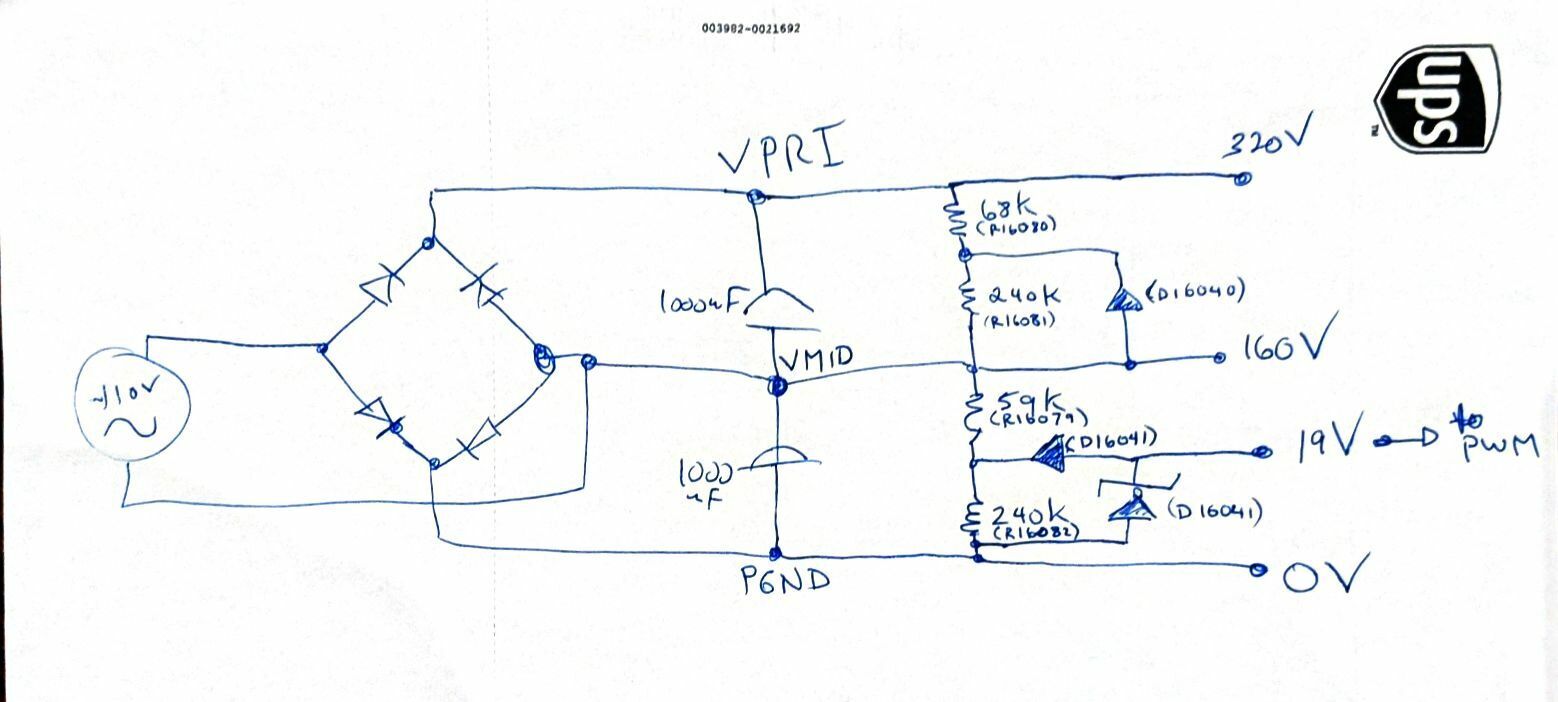
Sure. The attached is how I think the circuit is organized. I don’t quite ‘get’ how the 19V zener is providing 19V in this, but working devices do in fact read 15-18V when running.
D16040 reads with 0.68 forward voltage drop. I wonder if there is a reverse voltage avalanche breakdown property that is allowing some current to pass to the cathode of D16041.
Couldn’t agree more! Never suspected the riser and main board to be faulty as the power supply gave me most troubles.
Did you put in a new STA508 when you put it all together? Or were you just testing the power supply? Also you can get it from Mouser... its a STA50813TR
https://www.mouser.com/ProductDetail/STMicroelectronics/STA50813TR?qs=sGAEpiMZZMtxdzBvM0rKcUDV0cGqXNcOK%252bjnReF%252bddw%3d
Never done this. Looking forward to your results!
Well, I was able to change the DRAM out without much issue. I used kapton, some foil, and the hakko hot air rework. Then I cleaned the pads and put new parts down. Unfortunately, it did not fix it. That pretty much confirms that the issue is probably a cracked solder ball under the BGA, or head-in-pillow or some other similar type defect. I thought about putting it in the xray but it is so hard to see some of these defects and regardless of what I found, it was not repairable.
Any chance you remember what dram you ordered? What amp do you have the CP 100 or the ZP 120?
I just put the amp partially back together without the STA508. According to gruv2ths the amp should boot normally (white flashing light). Thanks for the mouser link but I found a US based eBay seller and ordered 2 at $10 each. They should be here next week.
I had a typo: I mislabelled the zener. It is D16035 on the board (not D16041).
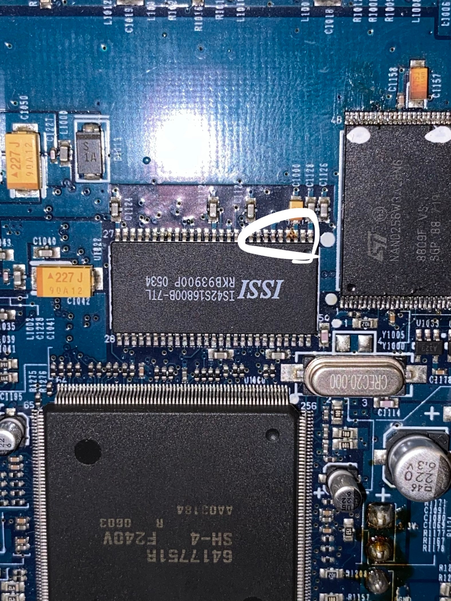
Found the dram chip one of the pins looks a little weird, otherwise no visible damage I ordered 2 should be here in a couple of days!
I'll check if the 36v turns back to 15v at standby. It's only temporary until I find the matching part..
Have you tried yours with a known working riser board and logic board? I'd like to still know more about the orange light error. Seems with all voltages correct the orange light refers to the riser/logic board or amp chips.
I have a Gen 2 Play 5 that has a short on the power supply. Doesn't seem to be much info out there on them.
ando1... while you are waiting, I am interested in something. Please confirm you have voltages on the PRIMARY side the PWM transformer (it should be AC). If you do, could you please lift the transformer from the secondary side and test that you have voltages on the secondary transformer pins while they are not connected? I am interested to see if something on the secondary side of the circuit is pulling down your voltage (short?) or if perhaps that transformer is indeed bad. If the transformer is good, you should see voltages on the output pins of that transformer. If you get AC voltages on the primary (output from the PWM) but nothing on the secondary, then your transformer is likely toast. If you suddenly have voltages on the lifted secondary pins, then your transformer is good and your problem is down stream. You can also test for a short while that side of the transformer is up off the circuit.
Thanks for the suggestions m0untainman. I measured the primary voltages (now with the shorted STA508 removed) my readings are below. How do you suggest I remove only the secondary side of the transformer out of the circuit?
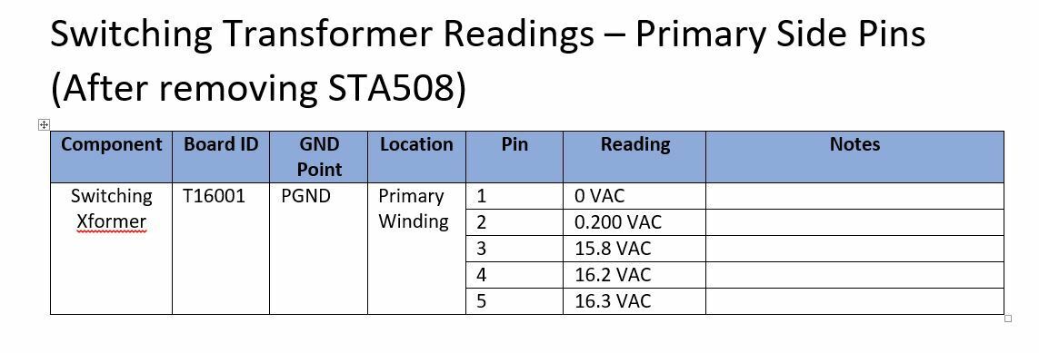
Your voltages on the primary look good. Unsolder the secondary and try to gently bend it up. Stick a business card or something that has no conductivity underneath it to keep it from touching the contacts below. If that's too difficult, you could remove it and just wire some jumpers with alligator clips to the primary.
Be careful not to short anything because that PWM will go kapow. Take it slow and methodical.
Be careful not to short anything because that PWM will go kapow. Take it slow and methodical.
Page 15 / 17
Reply
Enter your username or e-mail address. We'll send you an e-mail with instructions to reset your password.