The amp has no power. Is there an internal fuse for this unit?
Has anyone taken one apart?

Page 9 / 17

I have for sale, 3 Connect:Amp power boards with chassis and bottoms (wifi antennas and white plastic pan) that are tested with a known good logic board. I can send you videos of them working with a pair of JBL towers.
You just drop in your logic card and your in business.
Message me at gruv2ths@gmsil.com if your interested.
You just drop in your logic card and your in business.
Message me at gruv2ths@gmsil.com if your interested.
Toden,
The flashing orange on mine was due to a bad driver IC on the logic card. It is a 14 or so pin IC.
Mine would flash orange and white when i push play, the app keeps playing like nothing is wrong yet no sound from the amp.
The flashing orange on mine was due to a bad driver IC on the logic card. It is a 14 or so pin IC.
Mine would flash orange and white when i push play, the app keeps playing like nothing is wrong yet no sound from the amp.
Blinking orange and white is fault mode. The Amp is either too hot, or there is a short. Make sure there is adequate ventilation and check that the wiring is not frayed or sticking out, causing a short.
Couple of observations.
-if you are getting the 3.3,8ish,15 on the secondary then the bias converter PWM is working correctly.
-The reason you are seeing 0V on the transformers pins is because you are looking at AC with your meter set to DC. Those biases measured in the logic card say to me that the bias converter is running and the output is making its way to the logic card. Good sign
-I can only think of one thing left to do, and that is measure the output of the buck converter on the bottom of the logic card. There is a inductor with a (normally) yellow electrolytic cap. Solder a wire to the striped side of the cap and put the card back in and plug in. You can put the red lead on the wire and the black one to chassis. Should have 1.5V output.
Do you know much about reading serial (UART) from a computer? You may have noticed a 4 pin header under the EMI shield that you removed. There may be some diagnostic clues coming out of that serial headder.
The one I am working currently has a confirmed good power and riser boards and shows up in the Sonos app but when you push play I get orange and white blinking leds. Wanting to read that header and see if it can give me a clue as to why mine shizes the bed when I push play.
i have 4 amps, that goes flashing orange and white when play is pressed. have you got any luck on that issue???
Hello.
I have almost the same problem as runecal. i have 6 amps that have gotten overvoltage. i have changed the 2 large caps. and a little thermistor and the fuse.
i bootes up and is connected to network, but when i tries to play music, it turns to blinking orange.
any idea???
I have almost the same problem as runecal. i have 6 amps that have gotten overvoltage. i have changed the 2 large caps. and a little thermistor and the fuse.
i bootes up and is connected to network, but when i tries to play music, it turns to blinking orange.
any idea???

Hi
I hope there is someone who can help me.
I have a ZP120 that flashes orange and white.
It will not play music, but if I hold the mute button for a few seconds, I can make it light dimmed white and I can play music.
But only for 2-3 minutes, then it pauses again and starts blinking orange and white again.
I have had it apart and there was a little corrosion on the print card, I have cleaned the corrosion and I could not see that something was wrong with the print.
Does anyone have an idea of what it can be?

Thanks again. Appreciate the help!
@brumster, yes those are thermistors part# SCK-054. Also hard to find here in the US.. I’ve found those on AliExpress as well.
Thanks @noguruhere! Appreciate the response. I don't suppose you know what the green ones are to the right hand side of the right storage cap do you? The ones between the bridge rectifier and the grey resistor show in the first image I posted? Thanks again!!
They are varistors. Part# TVR14241. So far, the only place I found them were on AliExpress. Your amp will work without them but I wouldn’t operate it for too long as they are there for protection.
All, great thread running here.
I'm wondering if I can drop a question in here rather than starting a new thread? Does anyone have a view on the various ceramic caps in the zp120? In particular would anyone know what I would need to replace the two large yellow ceramic caps that are located between the two storage caps with? they appear to be labelled D16033 and D16034. Thanks for any help you can provide.
I'm wondering if I can drop a question in here rather than starting a new thread? Does anyone have a view on the various ceramic caps in the zp120? In particular would anyone know what I would need to replace the two large yellow ceramic caps that are located between the two storage caps with? they appear to be labelled D16033 and D16034. Thanks for any help you can provide.
My sonos ZP120 got wet with soft drinks by accident, I'm in the process of soaking in all these information. I shall try to fix it myself fingers crossed. Thank you very much everyone for creating this forum.
Is there anyone here that is willing to repair a ZP100 or ZP120. I am on my 2nd iteration of each of these. One was replaced out of warranty by sonos (thanks), the other not. I know the end is nigh. Thanks

@benbendog, Congrats... "Bob is your uncle"
Always good to hear when someone fixes it, because Sonos won't 🙂 Nice work.
Always good to hear when someone fixes it, because Sonos won't 🙂 Nice work.
Aynamne, use the cheat sheet I made above and see if you have any of the bias converter working.
There was another guy on here with the same symptom as you and I think he gave up. Not sure what causes that.
There was another guy on here with the same symptom as you and I think he gave up. Not sure what causes that.
Congrats!! Feels good right?!?
Hi guys,
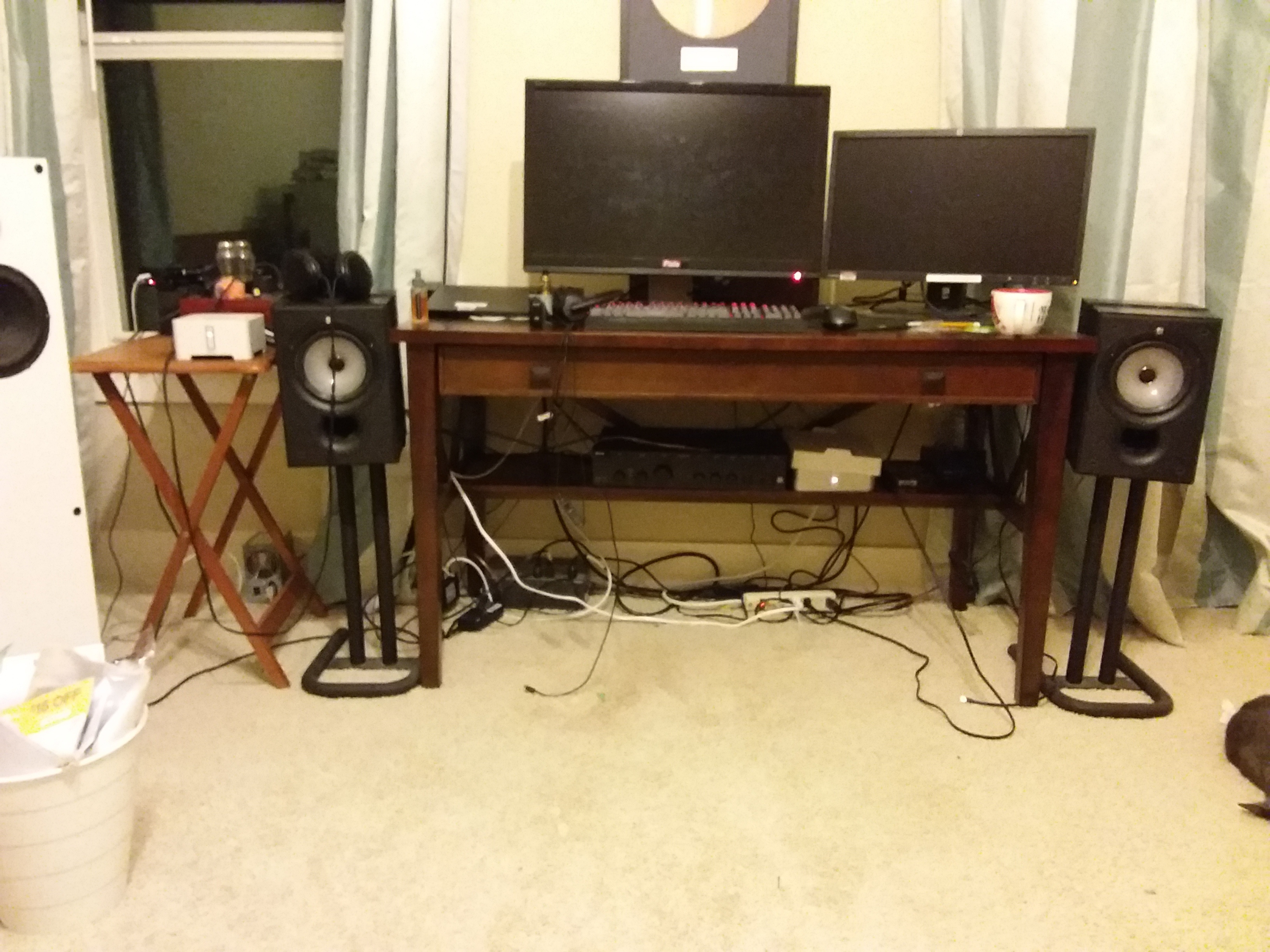
I have a great news to report, I found I was shorting the transformer contact after I installed the mainboard, I was really lucky nothing damaged. I isolated the contacts and guess what, the white LED turned on right after power on! It took me no time to add the zp120 to my Sonos setup and it is driving my KEF speaker replacing the Arcam:
The white box under the table is the zp120, the one one the small table is the zp90.
My next steps are to put everything together and fix the wifi antenna.
Thanks again for the help. I like this forum, I hope with my little experiences, I can help someone in the the future.
Thanks, I have done all that though (factory reset, hold power + v+), etc … and the light just stays solid white. And none of the ethernet lights on the back are blinking.
Wow, that was a long but interesting read. I have a ZP120 with the "stuck on white LED", no ethernet traffic. It looked inside and nothing obviously damaged. I rung out the front panel board and everything looks OK there. Should I start another thread? Any ideas what the white LED means? It comes on within a second of plugging and just sits there.
NVM, after putting everything together, now i can see the two RTN points are shorted probably by the main board. I will do more detail measurements tonight.
Hi gruv2ths,
Can you confirm if I should short the two RTN points?
Thanks,
Can you confirm if I should short the two RTN points?
Thanks,
That's great news. Now IIWY, I would be sure those leads are coated. Get some liquid eletric tape and slather them. The reason is the electronics on that board are really not friendly to shorts. That PWM blows by just looking at it and its a tough part to get. Both gruv2ths and I have blown those multiple times.
I believe it was gruv2ths who said you could short the two RTNs and all should be good.
Let us know if its all working... its great to hear when we get one up and running. 🙂
I believe it was gruv2ths who said you could short the two RTNs and all should be good.
Let us know if its all working... its great to hear when we get one up and running. 🙂
Hi Guys,
I managed to install the fixed transformer back to the power supply board:
I double checked all the connections then powered on. I was using RTN1 (pin1) as GND and I did get 3.3V output which means the primary is working now. On the other hand, if I use the same RTN1 or the CPU_GND, I got nothing from either the 8.4V or the 15.4V. I then switched the GND to RTN2 (pin3 of the secondary) and I was getting ~7.8V and 14.8V from both outputs. I was really happen to see that. It seems that the 3.3V and 5V/14V don't share the same GND. I remembered someone suggested to short them together but I was not sure if I should do that if by design they are separated.
I was very excited to put everything together and powered on. The good news is nothing blow-up but the bad news is the LED didn't turn on. I will have to debug it later. I am not sure if it is related to the GND connection.
Thanks again for all the help so far.
I managed to install the fixed transformer back to the power supply board:

I double checked all the connections then powered on. I was using RTN1 (pin1) as GND and I did get 3.3V output which means the primary is working now. On the other hand, if I use the same RTN1 or the CPU_GND, I got nothing from either the 8.4V or the 15.4V. I then switched the GND to RTN2 (pin3 of the secondary) and I was getting ~7.8V and 14.8V from both outputs. I was really happen to see that. It seems that the 3.3V and 5V/14V don't share the same GND. I remembered someone suggested to short them together but I was not sure if I should do that if by design they are separated.
I was very excited to put everything together and powered on. The good news is nothing blow-up but the bad news is the LED didn't turn on. I will have to debug it later. I am not sure if it is related to the GND connection.
Thanks again for all the help so far.
Page 9 / 17
Reply
Enter your username or e-mail address. We'll send you an e-mail with instructions to reset your password.