The amp has no power. Is there an internal fuse for this unit?
Has anyone taken one apart?

Page 10 / 17

Nice... so it was the pins :-)
I am very very hopeful this is gonna work for you... can't wait to hear!
I am very very hopeful this is gonna work for you... can't wait to hear!

Hi gruv2ths,
With the help of your pictures, I think this time I did an OK job recovering the transformer:
All windings now have expected connectivity and resistance. My plan is to flip the transformer (pins sticking up), glue it on the PCB, and use coated wires to connect it back to PCB. That way I can easy fix it in case something happened during the soldering process. I will keep decent gap between wires.
I will keep you updated.
Thanks again for the help,
-Tao
With the help of your pictures, I think this time I did an OK job recovering the transformer:

All windings now have expected connectivity and resistance. My plan is to flip the transformer (pins sticking up), glue it on the PCB, and use coated wires to connect it back to PCB. That way I can easy fix it in case something happened during the soldering process. I will keep decent gap between wires.
I will keep you updated.
Thanks again for the help,
-Tao
Hi gruv2ths,
Thank you very much for sharing the pictures. My secondary winding are still intact and I need mainly to figure out the primary connections. I think I got it from your pictures and I will give it a try.
You are correct this is the eBay sell with broken bottom. I cut a deal with the seller for $70 and I was willing to take the risk just for fun. 🙂 The condition was not as bad as I thought since I can see nobody has tried to fix it and the damages are all mechanical. I hope will fixing the transformer it can be back to life.
Please give me a price for the transformer as well as with the bottom.
Thanks again for the help,
-Tao

So here are a few pics that may help. This is the bias converter transformer that I have for sale if you need it.
Dude! One word comes to mind.... Butcher!! Lol jk
We all had to learn sometime.
I will say that I am concerned about the damage to the pcb. The reason is the high voltage on the primary side. They can midigate creapage and arching in the pcb, but with jumpers all bets are off. So let’s hope we can clean that up, without any fireworks. Dim bulb will be helpful I terms of delivering current to a short. But then again with those huge storage caps across the 300 volts, definitely tread lightly.
I think I know of the unit you are working on. Was it recently on eBay? $100ish no bottom. (Well the bottom mounting chunks were still there) yes if you look closely in the eBay pic you can see the ripped off WiFi connector. I thought long and hard about talking a risk in that one.
I have a bottom and the WiFi antenna for you if you need it. I can give you a package price with the transformer if you like?
Will send the transformer pic later this afternoon.
Hi gruv2ths,
I managed to get the transformer out but I did a horrible job that I broke off a few PCB pads (should not be a bit deal since worst case I can use wires to connect them back). On the primary side, there are total 8 wires coming out of the transformer that I lost the ordering after taking them out. I took a few pictures to show what I have. Can you take the same from your working one?
I probably will need to get a working one from you anyway.
Thanks,
Hey man,
Yes your frustration is defiant understood by myself and M0untainman.
So to unsolder the transformer leads takes patients. Lol
I do it in 3 steps.
1) wick out as much Sonos solder as you possibly can.
2) Now flow in as much of your solder back into each hole. This will help transfer heat to the stubborn Sonos solder that is left.
3) wick it all out.
4) on the still stuck pins I get with the iron and wiggle with a tweezer as you remove the heat. This will hopefully keep the solder from cooling back on the pins.
Hi gruv2ths,
Thanks a lot for the reply and I feel so good someone speak the same language and understand my frustrations. :)
The ZP120 I got had pretty bad mechanical damaged (may have been dropped multiple times, one of the wireless antenna wires was missing), but it has no sign of electrical damage upon close inspection which is a good sign. I trace through the circuit and the 10ohm big resistor is fine and I AM getting ~340V DC voltage on primary pin5. I got very low and stable ~1.5V on both pin3 and pin4 which should be oscillating to generate the current flow for the secondary coils. Then I confirmed I have open from 4 to 5, but ~1.4ohm from 3 to 4. My conclusion is the coil is broken between 4 to 5 more than likely due to shocks that the transformer moved which stretch the coil connections inside. All my secondary coil resistors values are good but without primary...
I am in the middle of removing the transformer, it is not an easy job 😞. My company has state of art rework equipment and technicians but not at my home. 🙂 Please share your tricks on de-soldering. I didn't want to use a hot gun yet.
I am certainly interested in getting your used transformer since I am not sure if mine is repairable. Please send me an e-mail to: twang55@gmail.com for the price info.
I recently just repaired a ZP90 and I was lucky that it was just a blown rectifier diode. Now it is singling in my home office with a dedicated Amp. I want this ZP120 to replace it so I can have the ZP90 for my hifi system. I will have Ethernet connection so wifi is not a must for me.
Hi Guys,
Wow this is timely for me as I just t-shoot a power board on a ZP-120 with water damage. Man that board was like a bad dream. I had for my first time ever, a transformer winding open sort of like you describe. What i found was he following:
- Check the 10 ohm resistor showing through the hole just to the left of VPRI. Yours is OK if you see 300ish Volts on pin 5 of the transformer primary. This resistor is in series with the transformer primary and blows a lot.
- I also had a trace blown open at the pin 5 through hole. No power to the primary at all.
- Most importantly I did not see any resistance between pin 5 and pin 3. Primary open. I removed the transformer and found under my microscope that pin 3 was blown open to its winding termination pin. There was just a 1/8th inch of wire peaking out of the windings. It is magnetic wire so what you do is put a blob of solder on your solder iron tip and let the wire sit in molten solder until the insulation melts off. Then just soldered a wire from the little piece of magnetic wire to the pin at the bobbin base.
-Same transformer secondary side, if you wee 3.3v but not 8.5 nor 13 you likely have an open where the 2 secondaries short in the PWB, take a small piece of wire and short them back together. I see this fail on 90% of the Amps i fix.
Lots if simultaneous fails on my board, worst onion ever.. Felt good to see all 3 voltages on the secondary.
If your winding is blown open in the windings, then fixing that transformer is way beyond my help.
I can however sell you a used but guaranteed working transformer.
Let em know what you want to do.
I have had a few repairs lately where I have fixed the power board but can't resurrect the logic board. I intend to put a few working power boards with or with out the chassis on sale on eBay.
Please let me know if there is any interest in tis as well.
I really like this forum thread!
While I am trying to get the transformer out, I found it a bit loose from the frame so the disconnect could be due to mechnical damage. I will find out after it is removed.
Thanks again. I will try all the suggestions tomorrow including removing the transformer. It will not be that easy...
BTW, for 115v ac input, the voltage selector switch should short the two white wires, correct? The voltage selector on my
Zp120 was damaged so I have to solder a wire to short them since I live in the US. I figured either way I should not damage anything.
BTW, for 115v ac input, the voltage selector switch should short the two white wires, correct? The voltage selector on my
Zp120 was damaged so I have to solder a wire to short them since I live in the US. I figured either way I should not damage anything.
Look really closely at that transformer for a burn mark or something to validate that the transformer may be bad. Since you have an EE background I am sure you know it takes something super nasty to blow a transformer and its fairly rare to take those out. I would also check the solder joints on it as well as the connectors leading into the transformer. Its possible one of them has a bad solder joint or the pins connected to the transformer wires got wonky and may just need to be re-seated. Reflow the solder on the pins and see if you get some continuity. Try testing the continuity from the other side of the board on the transformer pins...that way you can wiggle them a bit. This is sort of why I recommended to just remove it it and test it out of circuit as you will know really quickly if its bad or not, as opposed to a poor solder joint.
Even though the PWM is oscillating... double check its output voltages. That part is the most sensitive of the entire board and its been really easy to blow those with a simple short.
Even though the PWM is oscillating... double check its output voltages. That part is the most sensitive of the entire board and its been really easy to blow those with a simple short.
Hi m0untainman,
Thank you so much for the detail explanation, That helps a lot.
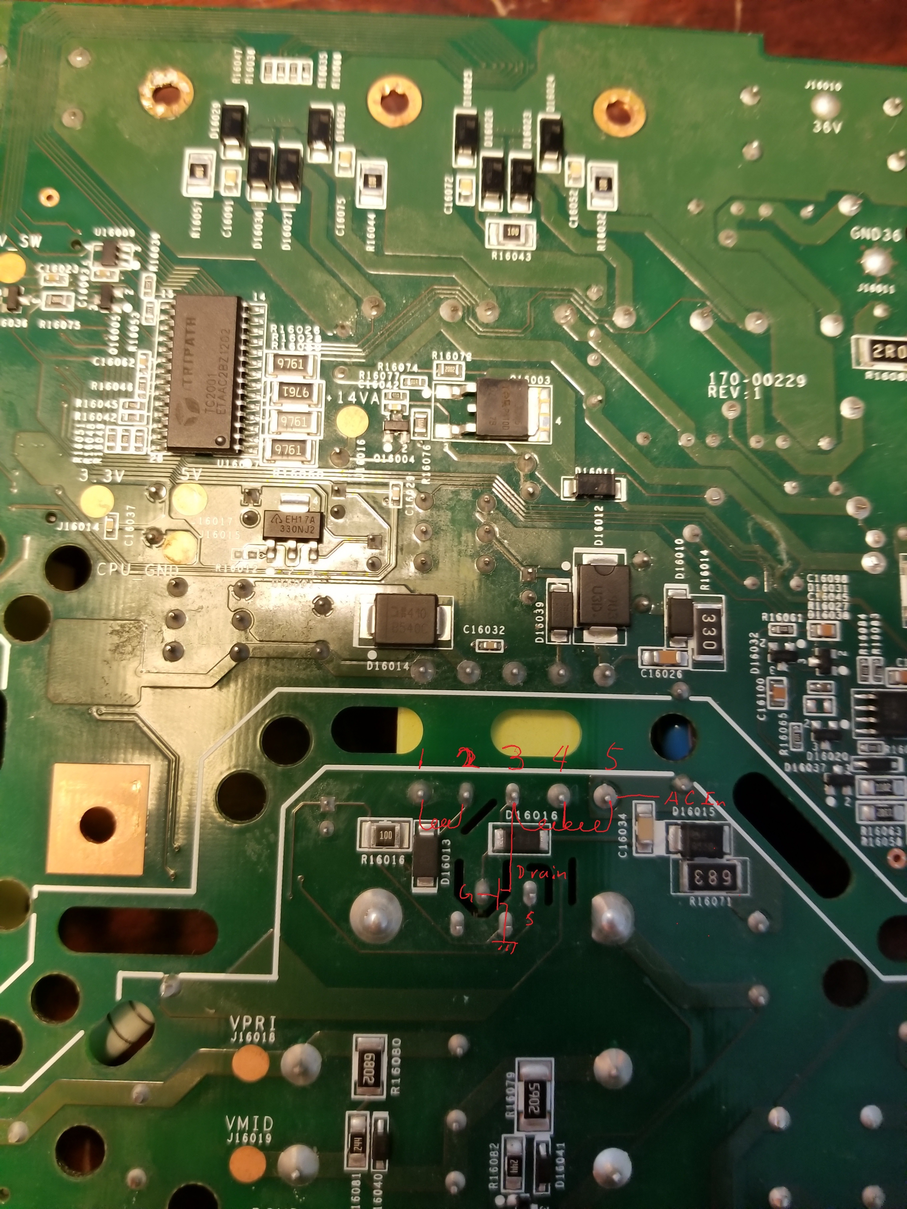
I did all the measurement with the transformer on the board and I understand your point on other components' impact for the measurement (I have an EE background doing chip design and debug works :)). However for this specific case, I am only checking the resistance of the transformer coil resistance. The picture is my understanding of this circuit:
the resistance between 1 and 2 is OL with with FLUKE 179 DVM, between 3 and 4 is 1.8ohm which looks for me. but either 3 and 5 or 4 and 5 are OL which to me means the coil is broken somewhere between 4 and 5 inside the transformer, other parallel circuit would make the resistance smaller but not bigger/bigger.
with powered on, I got about 340V DC voltage on pin 5. but only stable ~1.5V from either 3 or 4. I have checked the PWM chip: the feedback (oscillating), VCC all looked fine. there is just no current flow from 5 to the PWM drain to generate voltage on the secondary coils so they all stay at 0V (I am expecting to see 3.3v, 5V, ~14V). I am not sure what 1-2 are connected to.
Any inputs will be very helpful.
Thanks,
-Tao
Thank you so much for the detail explanation, That helps a lot.
I did all the measurement with the transformer on the board and I understand your point on other components' impact for the measurement (I have an EE background doing chip design and debug works :)). However for this specific case, I am only checking the resistance of the transformer coil resistance. The picture is my understanding of this circuit:
the resistance between 1 and 2 is OL with with FLUKE 179 DVM, between 3 and 4 is 1.8ohm which looks for me. but either 3 and 5 or 4 and 5 are OL which to me means the coil is broken somewhere between 4 and 5 inside the transformer, other parallel circuit would make the resistance smaller but not bigger/bigger.
with powered on, I got about 340V DC voltage on pin 5. but only stable ~1.5V from either 3 or 4. I have checked the PWM chip: the feedback (oscillating), VCC all looked fine. there is just no current flow from 5 to the PWM drain to generate voltage on the secondary coils so they all stay at 0V (I am expecting to see 3.3v, 5V, ~14V). I am not sure what 1-2 are connected to.
Any inputs will be very helpful.
Thanks,
-Tao
I just got a ZP120 that can't power on. I have tracked down the main power transformer is dead: the primary windings are broken: from 1(RTN) to 2 is OL, 3(RTN) to 4 is 1.8ohm (this is the only good one), 3 to 5 is OL. Due to this problem, all secondary outputs are 0V.
I am wondering if the transformer part can be purchased anywhere. Otherwise I am open to other alternative Solutions like external power supplies?
Not dead... nobody has had anything broken or came back :-)
Did you test that transformer off board? That's critical as being on board can give you different numbers depending on the circuit or if something is blown/shorted. Transformers do not blow very often and are fairly stable. Take a really good look at it off board and see if you see any evidence of charred marks or something if it registers bad. If it registers good, then its something else and you will need to do a bit more detective work.
If you are 100% sure its the transformer, you usually can find a number or code on it. You can search for that on Alibaba or reach out to some of the Chinese transformer manufacturers and see if they can find it. If not, you have the input and output voltages, so you can can give that to them as well to see if they can get a match. You can generally determine the winding ratio by dividing the input by the output... i.e. 120v to 3.3v = 120/33 ~ 36:1 winding for step down. You will need to calculate that for each input/output. You could also unwind it yourself and get an accurate winding count. Since its the main transformer, its a reasonable chance that its standard. If you can get the MFR, you can always contact them and they should have them on hand. However, there is a chance its a custom wind, and you would need to reverse engineer those windings yourself.
The last possibility is check eBay for a seriously bad ZP120 and see if you can grab it for $20 and just pull the transformer out of there.
I just got a ZP120 that can't power on. I have tracked down the main power transformer is dead: the primary windings are broken: from 1(RTN) to 2 is OL, 3(RTN) to 4 is 1.8ohm (this is the only good one), 3 to 5 is OL. Due to this problem, all secondary outputs are 0V.
I am wondering if the transformer part can be purchased anywhere. Otherwise I am open to other alternative Solutions like external power supplies?
Did you remove the transformer and check it? The only way to really know is to test it off the board. Transformers are tough to go bad...it takes a lot to blow one.
If you did test it off board, there usually is a number on the transformer. You may be able to go to Alibaba and search for the number/MFR to try to get a match. The other option is to get the size and windings (i.e. the specs) and try to get a replacement. If its the main Xformer, then that can be fairly standard as its a step down to generic voltages. You may be able to determine the windings from the front side voltages to the secondaries based on the output voltage (i.e. 120v to 3.3v == 120/3.3 ~ 36:1 winding, so on and so forth). You can also reach out to the MFRs and state the input/output voltages, and they can usually find one for you. You would need to give them the size... maybe some pics, etc.
Final option is look for a ZP120 on eBay that is dead as a door nail and try to get it for $20 for parts.
I hope this thread is not dead.
I just got a ZP120 that can't power on. I have tracked down the main power transformer is dead: the primary windings are broken: from 1(RTN) to 2 is OL, 3(RTN) to 4 is 1.8ohm (this is the only good one), 3 to 5 is OL. Due to this problem, all secondary outputs are 0V.
I am wondering if the transformer part can be purchased anywhere. Otherwise I am open to other alternative Solutions like external power supplies?
Hey Ando,
No luck but no time to mess with them.
Check the 10 ohm resistor. It is axle leaded and 2 W and on top of the board.
If it reads 10 ohms then replace the PWM again.
That SHOULD get you back in the road.
No luck but no time to mess with them.
Check the 10 ohm resistor. It is axle leaded and 2 W and on top of the board.
If it reads 10 ohms then replace the PWM again.
That SHOULD get you back in the road.
Hey gruv2ths. Sorry I haven't been on in a while. Work has been nuts and getting ready for vacation. I actually screwed up the other day when I was taking some voltage measurements and accidentally touched 2 pins on the PWM when it was powered on. I saw a small spark but no smell/smoke, however now I do not have the bias voltages on the secondary any more. I checked the fuse hoping it was just that but no go. I am really not sure I want to keep going on this as I am not sure I can bring this amp back to life. Have you made any progress with the other amps that you were troubleshooting?
The idea is to make sure your non functioning logic board is getting the bias it is expecting. We can compare what you read to what my working riser card is delivering. So check all the riser card output pins to chassis.
Ah I see. Sorry I have not checked for any voltages here before. Where should I check and what values should I expect?
No I meant the voltages at the riser board connector with the logic board removed.
If you mean the 1.5V from the buck converter, yes I am getting that. Here is the post from a while ago: https://en.community.sonos.com/advanced-setups-229000/repair-zp120-17442/index5.html#post16189903
Ando, did you get the voltages coming from the riser board to the logic board?
Thanks gruv2ths. That makes me feel better about those voltages. I received the new STA508 last week and planning on replacing it this week. After I replace it, I will try powering on the amp again and cross my fingers.
Ahhh yes, that would do it 🙂
Page 10 / 17
Reply
Enter your username or e-mail address. We'll send you an e-mail with instructions to reset your password.