The amp has no power. Is there an internal fuse for this unit?
Has anyone taken one apart?
Page 6 / 17
Remind me what your Amp was doing, or how it was failing?
I use the hakko 851 -- it is one of their pricier ones. I have nothing to compare it to, because it is all I have ever used. My amp was the blinking white light. After debug I found that it was stuck in the bootloader due to the dram memory test failing.

That's a bummer. Which Hakko do you use? I need a hot air tool. Crazy range in prices.
Remind me what your Amp was doing, or how it was failing?
Remind me what your Amp was doing, or how it was failing?
Well, I was able to change the DRAM out without much issue. I used kapton, some foil, and the hakko hot air rework. Then I cleaned the pads and put new parts down. Unfortunately, it did not fix it. That pretty much confirms that the issue is probably a cracked solder ball under the BGA, or head-in-pillow or some other similar type defect. I thought about putting it in the xray but it is so hard to see some of these defects and regardless of what I found, it was not repairable.
Never done this. Looking forward to your results!
I went ahead and ordered 2 2DRAM parts since I don't know which is bad. Anyone tried this replacement? I might have to remove the shield. If not I'll remove the parts with hot air and then put the new ones down.
I lifted the shield can and connected to the UART -- here is what I get.
So I don't forget the pins are vdd,rx,tx,gnd …
U-Boot 1.1.1(1-16-3-0.9), Build: 0.9
MPC8272 Reset Status: External Soft, External Hard
MPC8272 Clock Configuration
- Bus-to-Core Mult 3x, VCO Div 4, 60x Bus Freq 16-50 , Core Freq 50-150
- dfbrg 1, corecnf 0x10, busdf 3, cpmdf 1, plldf 0, pllmf 3
- vco_out 400000000, scc_clk 100000000, brg_clk 25000000
- cpu_clk 300000000, cpm_clk 200000000, bus_clk 100000000
- pci_clk 33333333
CPU: MPC8272 (HiP7 Rev 14, Mask unknown [immr=0x0d10,k=0x00e1]) at 300 MHz
Board: Sonos Wembley
DRAM: 32 MB
DRAM test
Test complete - 1 errors, error pattern 00400000
### ERROR ### Please RESET the board ###
There was another guy on here with the same symptom as you and I think he gave up. Not sure what causes that.
I finally got back to this -- checked all the DC voltages and they all match your reference. Even with my fluke truerms I didn't validate the secondary but I am guessing I referenced to the wrong point. The DC busses all look OK.
I am thinking to pop off the shield can on the logic board to get at the UART. Any other thoughts? Still a solid white LED.
Sotis,
Sorry this took a long time.
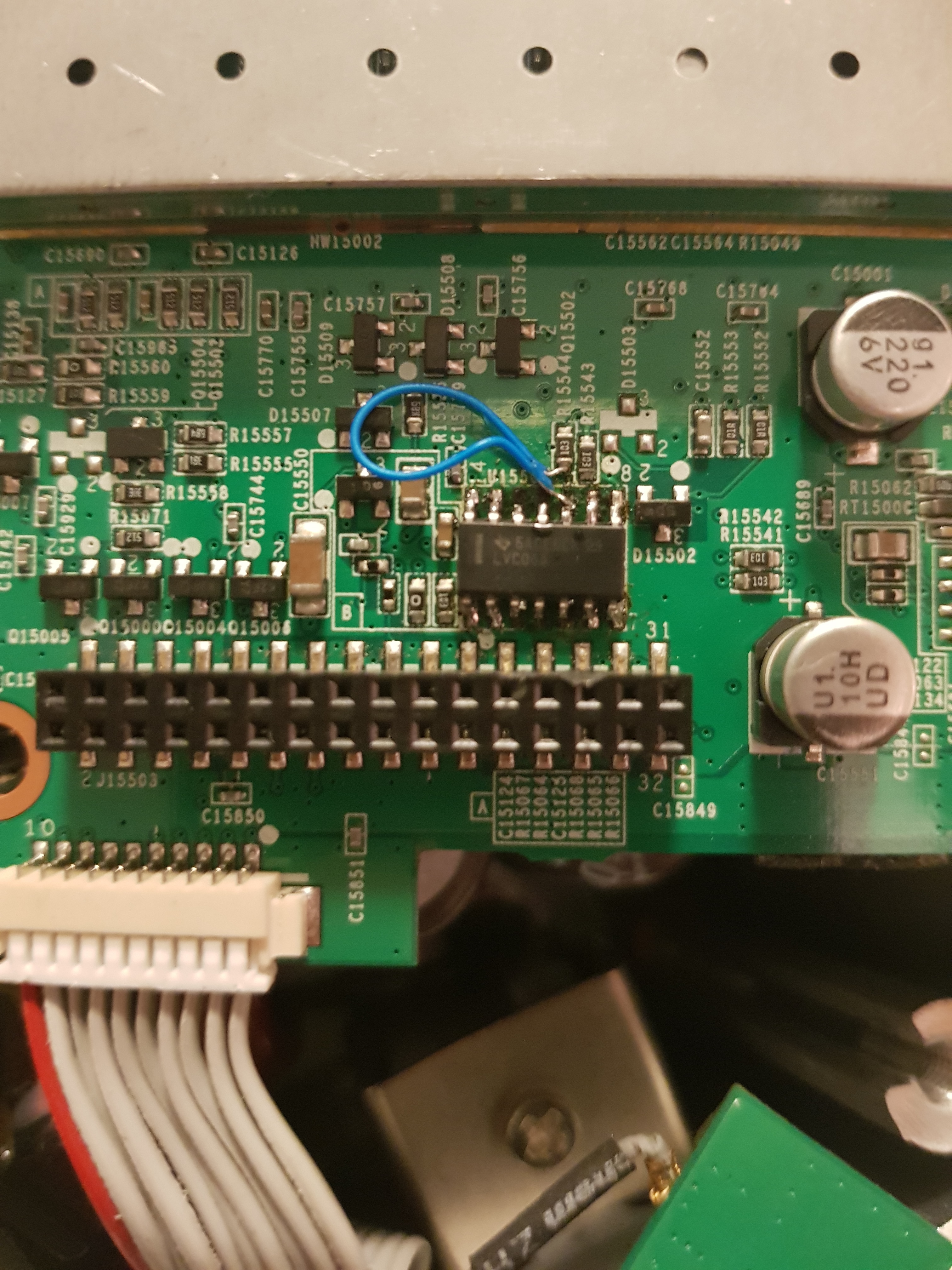
So can't help you with all the pins, but but was able to find continuity for a few.
The continuity is between the driver ICs output to the 32 pin connector next to it.
(look at the silk screen around the connector, you will find the pin number guide there)
IC Connector
2 4
4 5
8 23
Sounds like you just may need to get the 36V power converter enable connected.
Maybe if the above doesn't help, You can look at the datasheet for the IC and look at the input pins and see which ones go high when you push play. and go from there.
Sorry this took a long time.
So can't help you with all the pins, but but was able to find continuity for a few.
The continuity is between the driver ICs output to the 32 pin connector next to it.
(look at the silk screen around the connector, you will find the pin number guide there)
IC Connector
2 4
4 5
8 23
Sounds like you just may need to get the 36V power converter enable connected.
Maybe if the above doesn't help, You can look at the datasheet for the IC and look at the input pins and see which ones go high when you push play. and go from there.
Hello gruve2ths.
Do you think you can help me locate the missing pins3,4,5 ,11and 12
Best regards Sotis
Do you think you can help me locate the missing pins3,4,5 ,11and 12
Best regards Sotis
Gruv2ths
Is there a another way to figure that out?
I will do som measurment tomorow and let you know .
😃
Is there a another way to figure that out?
I will do som measurment tomorow and let you know .
😃
sotisg69,
You have to zoom way way in to the pictures that i attached to see traces.
As you can see most of the pins of that IC via down underneath the pads so no visible traces can be found. I suspect the inputs to that chip all come from the controller. The outputs are likely that connector next to the chip.
Hello gruve2ths excellent jobb back there once again. Iknow i almost kill it
I can se that the pin 8 from Ic goes to R15543
pin 9 ? the same?
pin 10 R15544
but i missing
pin 3,4,5 and must be sure 10,11,12
Please !:P
I can se that the pin 8 from Ic goes to R15543
pin 9 ? the same?
pin 10 R15544
but i missing
pin 3,4,5 and must be sure 10,11,12
Please !:P
Sotisg69,
Hope this helps.
Hope this helps.
sotisg69
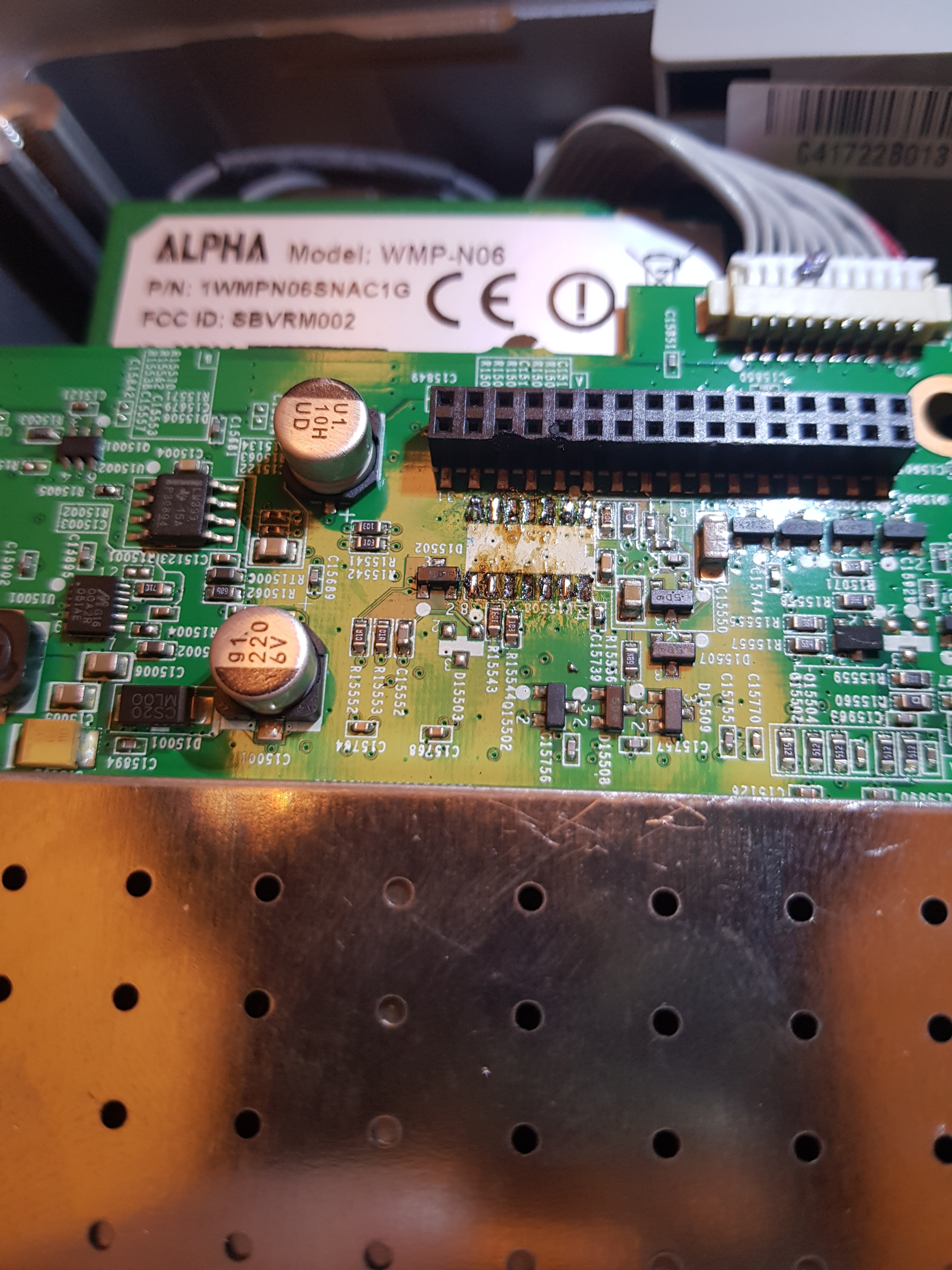
Oh my! Well that's not good.
What I would do is take some isopropyl alcohol with an acid brush and clean away the flux and see what is left. Also Tin the pads that are left once clean.
I will take a pick if a good board. Give me a little time.
Oh my! Well that's not good.
What I would do is take some isopropyl alcohol with an acid brush and clean away the flux and see what is left. Also Tin the pads that are left once clean.
I will take a pick if a good board. Give me a little time.
Gruv2ths thanks for the suggestions you got a point there. This pickture was taken before i soldered the new chip
I misled you. I forgot to reconnect the ribbon cable from the front panel controls! It attaches to the logic board directly below the Wi-Fi card. The controls now work fine. Your reply made me rethink what I had done. 🙂
sotisg69,
FYI-You won't see a voltage on the transformer secondaries unless you are in AC mode with a tru-RMS meter.
And the DC measurements need to be made with the black lead of your meter to either RTN36 or CPU_GND (they are shorted together as you mentioned)
A few observations, if your AMP shows up on your phone then you must have 3.3V, 8V(5V after the liner reg) and 15V. You most likely have your meter referenced to the wrong point.
Another though is that the logic card probably turns on the 36V supply through the driver chip that you replaced. So if you're not sure the solder is correct on that chip, i would concentrate there. Can you take a high res pic of the chip on the board for us to take a look at? We may be able to inspect your solder if the pic is clear enough.
Pdog,
Glad you got down to root cause.
Didn't know about the wifi card disabling the front button panel.
Thanks for the heads up on that.
Glad you got down to root cause.
Didn't know about the wifi card disabling the front button panel.
Thanks for the heads up on that.
Gruv2ths,
Bingo! It's the Wi-Fi card. With it removed the "static-like" noise is gone - even with a Sonos bridge (radiating RF) sitting next to the amp.
The Wi-Fi card is tricky to remove from the logic board. There is a mechanical clip on each side of the card and glue has to be removed to free it. There is also a small square foam pad glued between the Wi-Fi board and the logic board to secure the Wi-Fi card even more securely. I mention that should anyone else try to remove the Wi-fi card from the logic board.
The amp is connected to my music server by Ethernet cable and there is a pass through Ethernet connection to my bridge which then creates a Sonos net with my other units. As long as my amp doesn't need W-fi, I'm ok. Everything sounds and works fine. BTW, without the Wi-Fi card in the amp, the front controls on the amp are disabled. Fortunately a remote controller will still perform those functions.
Gruv2ths, thanks for the quick reply.
The CPU GND test point is 0 ohms (shorted) to the RTN36V test point but i notised that i dont have power after the transformer on secondary side See picture attachedthe
The CPU GND test point is 0 ohms (shorted) to the RTN36V test point but i notised that i dont have power after the transformer on secondary side See picture attachedthe

Good idea. I'll try removing the Wi-Fi card tomorrow and see what happens.
Pdog,
Wow this is a new one for me.
A few thoughts.
- I have noticed that when removing the antenna connectors from the wifi card it is exceedingly easy to mess up the termination given all the glue holding them in place.So you might want to try connecting the antennas one at a time and see if one of them makes the problem worse then the others. These things will work without all 3 antennas connected.
- Another thing you can try is to remove the wifi card all together and see what happens. Then just run it with the ethernet, for that test.
sotisg69
Hmmm, well that's not good. The 36V is what biases the output section.
So we need the 36V.
Can you check to make sure the CPU GND test point is 0 ohms to the RTN36V test point. If not they need to be shorted together.
The controller for the 36V and the 36V gate drive circuit is on the riser card between the power and logic boards. Near the transformer on the riser board. (the transformer is part of the gate drive for he 36V supply)
That is as good a place as any to start.
Let me look at one I have and will see if I can make a test aid.
Another thought, since the bridge was sitting near the amp maybe that wasn't a "fair" set-up. Even with the amp's antennas disconnected, maybe the amps logic board was picking up enough wi-fi signal from the bridge to start processing the Wi-fi signal and triggering the noise issue. I've packed everything up now. Maybe tomorrow I'll try again with the amp much further away from the bridge. However, even if the logic baord stops processing a Wi-Fi signal and the noise disappears (just a theory), it still leaves me needing a new logic board.
It's all fun though!
It's all fun though!
Hi Gruv2ths,
I had some fun trying to bridge a 0.1ufd cap across some of the caps on the logic board. It's not a practical thing to do on the small package caps but the principal of the problem-solving action is sound give the noise I'm hearing. Unfortunately my efforts had no impact. I don't think it is cap filtering issue. What I did discover, however, was when I disconnected the three amp antennas from the logic board, and therefore shut down the Sonos net, the noise almost entirely disappeared. The amp was hardwired by Ethernet cable to my music server and the amp had been broadcasting to the other Sonos units. I could still hear the noise faintly but not enough to make the amp unusable which was the case before. Unfortunately I don't want to use the amp as a stand alone amplifier unconnected to a net. I then tried connecting the amp by another Ethernet cable to a Sonos bridge. The Sonos net went into action, but the noise returned which I didn't expect. I thought the Ethernet would just be an in and out connection through the amp with no impact on the noise. In any case, it appears that the issue is in the logic board and not as simple as a damaged cap.
I'm not sure whether I want to sink any more money into the amp at this point.
Page 6 / 17
Reply
Enter your E-mail address. We'll send you an e-mail with instructions to reset your password.