The amp has no power. Is there an internal fuse for this unit?
Has anyone taken one apart?
Page 13 / 17

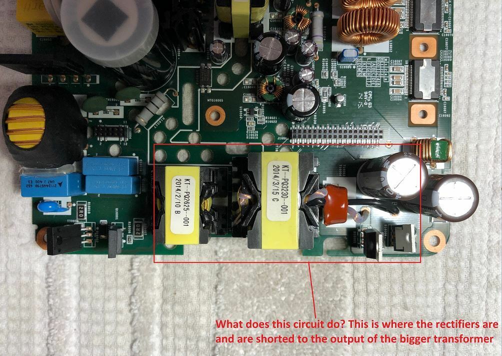
In order to do some more troubleshooting I wanted to check some of the voltage regulators that are mounted on the frame of teh amp, so I took the main board completely out and started looking around. All seemed normal until I got to 2 of the Schottky Barrier rectifiers near the 2 other transformers on the board (see pic for reference). I was taking some continuity readings and found that all 3 pins on both rectifiers seemed shorted. The traces on the board are hard to read but it looks like they are supposed to be that way? Anyway, to be thorough, I removed one of the rectifiers to test it and it tests good according to the data sheet. Positive lead on anode and negative lead on cathode gives beep on diode test. The other way around is open. I am puzzled by what this accomplishes

Ok. That is helpful. My comment at this stage is carefully check your solder connections and traces around the PWM. You may want to put in another PWM if you have one if the traces are fine. That secondary really needs to have voltages if the PWM is working. That PWM is sensitive and rather easy to blow. Be thankful that you have more 🙂
@m0untainman -
RE: Wait... I think your PWM is fine and I’m thinking that the secondary winding voltages just may not be measured properly. Looking at your secondary voltages downstream, everything looks nearly perfect. You shouldn’t be seeing the voltages if that secondary wasn’t working... so my guess is that your power supply is working fine. Getting back to the location where you had water damage... did you test the components near all that damage? Check diodes near that location as they are usually the first to go...
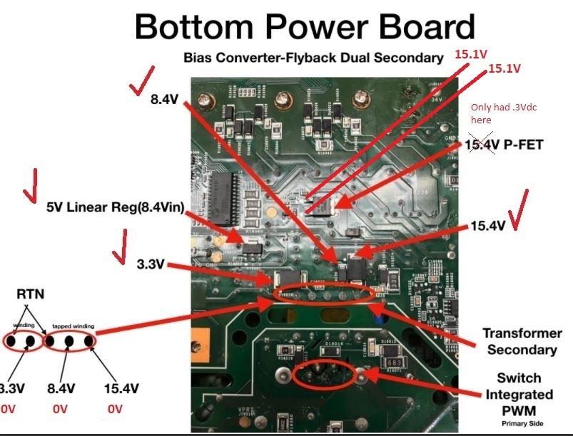
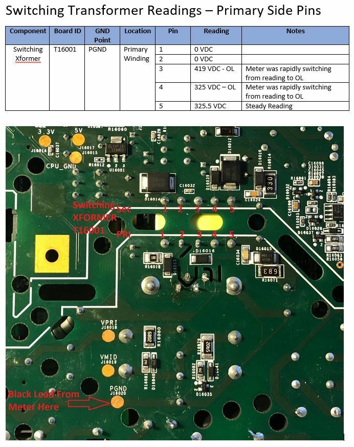
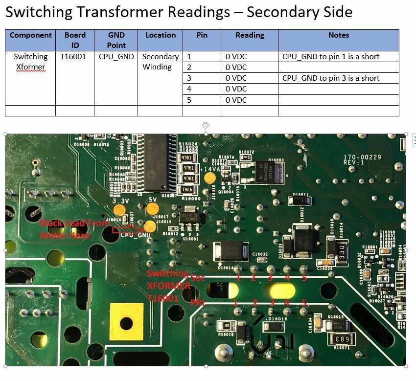
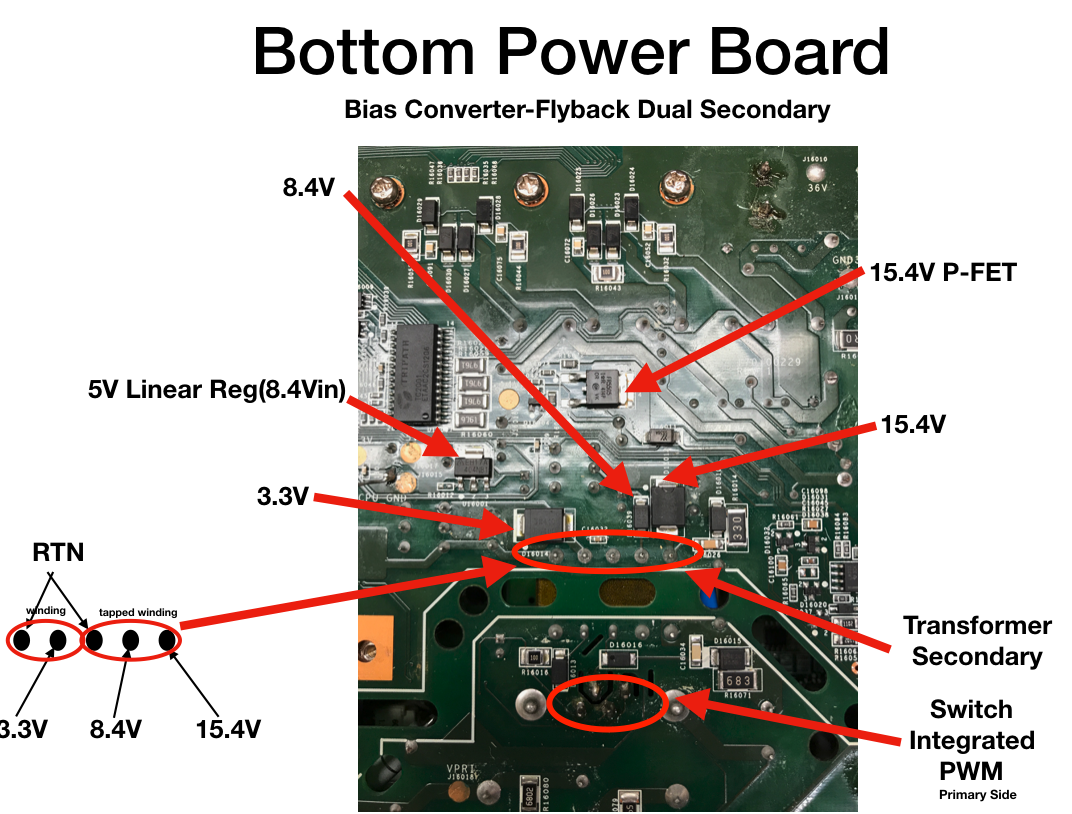
I am getting all of the proper voltages on the secondary side EXCEPT the pins on the transformer and the P-FET voltage. See the pic below for explanation.
Also RE: When you are checking the secondary, are you setting your ground on the RTN and the positive lead on the others? (I'm just dotting I's and crossing t's here)
Yes I am using the RTN points. I have also tried putting the black lead on the copper colored test point labeled "CPU_GND" as they are the same electrically as the RTN points (Verified by checking continuity)
Like you, I keep going back and forth between a power supply problem or something on the logic board. As far as checking the components I replaced on the logic boar, yes I have checked them and other components around them. All seem to be fine. This one is a real head scratcher. I am hoping either you or gruv2ths can provide some more insight.
Thanks so much for all the help you have provided so far!
RE: Wait... I think your PWM is fine and I’m thinking that the secondary winding voltages just may not be measured properly. Looking at your secondary voltages downstream, everything looks nearly perfect. You shouldn’t be seeing the voltages if that secondary wasn’t working... so my guess is that your power supply is working fine. Getting back to the location where you had water damage... did you test the components near all that damage? Check diodes near that location as they are usually the first to go...
I am getting all of the proper voltages on the secondary side EXCEPT the pins on the transformer and the P-FET voltage. See the pic below for explanation.
Also RE: When you are checking the secondary, are you setting your ground on the RTN and the positive lead on the others? (I'm just dotting I's and crossing t's here)
Yes I am using the RTN points. I have also tried putting the black lead on the copper colored test point labeled "CPU_GND" as they are the same electrically as the RTN points (Verified by checking continuity)
Like you, I keep going back and forth between a power supply problem or something on the logic board. As far as checking the components I replaced on the logic boar, yes I have checked them and other components around them. All seem to be fine. This one is a real head scratcher. I am hoping either you or gruv2ths can provide some more insight.
Thanks so much for all the help you have provided so far!
I am actually NOT getting those voltages on the secondary. I measured for AC and DC and both are 0V. Also I keep wondering about that P-FET voltage you said you have 15.4 volts on. I do NOT have any voltage o at that test point. Could it be that the PWM is not getting a signal to turn on the switching transformer voltage? Or is the fact that I have voltage on the buck converter and the other caps I mentioned on the logic board an indication that the PWM and the switching power supply are functioning normally?
When you are checking the secondary, are you setting your ground on the RTN and the positive lead on the others? (I'm just dotting I's and crossing t's here)
Yeah... then something isn't right with that PWM. So for gruv2ths and me, we see 13.03V on pins 1 and 3 on the PWM. You are showing 15v. That's an interesting delta, but certainly not a deal breaker outside the spec. Its possible that voltage is higher because the switching isn't working quite right (when I had no switching at all, I read 44v). Just for giggles, is the PWM hot?
Did you test the P-FET? (see https://www.youtube.com/watch?v=gloikp9t2dA)
Did you test the P-FET? (see https://www.youtube.com/watch?v=gloikp9t2dA)
@gruv2ths:
RE: I can only think of one thing left to do, and that is measure the output of the buck converter on the bottom of the logic card. There is a inductor with a (normally) yellow electrolytic cap. Solder a wire to the striped side of the cap and put the card back in and plug in. You can put the red lead on the wire and the black one to chassis. Should have 1.5V output.
I was able to get a wire on that cap (a bit of a test of my soldering skills) 😳 Anyway, I do have 1.5 VDC on that buck converter.
Also RE: if you are getting the 3.3,8ish,15 on the secondary then the bias converter PWM is working correctly.
I am actually NOT getting those voltages on the secondary. I measured for AC and DC and both are 0V. Also I keep wondering about that P-FET voltage you said you have 15.4 volts on. I do NOT have any voltage o at that test point. Could it be that the PWM is not getting a signal to turn on the switching transformer voltage? Or is the fact that I have voltage on the buck converter and the other caps I mentioned on the logic board an indication that the PWM and the switching power supply are functioning normally?
Wait... I think your PWM is fine and I’m thinking that the secondary winding voltages just may not be measured properly. Looking at your secondary voltages downstream, everything looks nearly perfect. You shouldn’t be seeing the voltages if that secondary wasn’t working... so my guess is that your power supply is working fine. Getting back to the location where you had water damage... did you test the components near all that damage? Check diodes near that location as they are usually the first to go...
I’m just trying to think this through to help narrow the location...
I’m just trying to think this through to help narrow the location...
Yeah. That looks good. Do you have access to an O-Scope? I would be interested in seeing if your PWM is pushing out a wave (switching).
Just checked the optocoupler and it seems fine according to the spec sheet. From the spec sheet:
Pins 1 and 2 are the IR Diode
Pins 3 and 4 are a NPN transistor
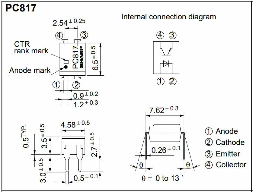
I set my meter on diode check setting:
- Pins 1 and 2 give a short beep and 0.528 reading
- Pins 3 and 4 give a short beep and 0.619 reading
That looks to be good
Also both the primary and secondary winding pins have the following continuity:
Primary:
Pins 1 to 2 = 0.08 Ohms
Pins 3 to 4 = 1.9 Ohms
Pins 3 to 5 = 2.8 Ohms
Secndary:
Pins 1 to 2 = 0.7 Ohms
Pins 3 to 4 = 0.7 Ohms
Pins 3 to 5 = 0.7 Ohms
This seems to be good as well.
I almost forgot. Check that you have continuity on the windings of your transformer. It’s not inconceivable to blow a transformer.
Test that optocoupler too (no power of course). Your multimeter can test it with the diode test function. Also, if you tested that secondary transformer, and aren’t getting the matched voltages, then yeah, it’s not switching. I can test the ohms across my pins on my PWM to list them here, but you can do the same if you have extras.
Couple of observations.
-if you are getting the 3.3,8ish,15 on the secondary then the bias converter PWM is working correctly.
-The reason you are seeing 0V on the transformers pins is because you are looking at AC with your meter set to DC. Those biases measured in the logic card say to me that the bias converter is running and the output is making its way to the logic card. Good sign
-I can only think of one thing left to do, and that is measure the output of the buck converter on the bottom of the logic card. There is a inductor with a (normally) yellow electrolytic cap. Solder a wire to the striped side of the cap and put the card back in and plug in. You can put the red lead on the wire and the black one to chassis. Should have 1.5V output.
Do you know much about reading serial (UART) from a computer? You may have noticed a 4 pin header under the EMI shield that you removed. There may be some diagnostic clues coming out of that serial headder.
The one I am working currently has a confirmed good power and riser boards and shows up in the Sonos app but when you push play I get orange and white blinking leds. Wanting to read that header and see if it can give me a clue as to why mine shizes the bed when I push play.
Thanks gruv2ths: I just saw your reply after I posted my recent reply about the PWM readings. Not sure about reading the UART. I have used serial ports in the past, but only to connect to consoles on enterprise class network switches.
I will have some time later to try your suggestion about measuring the 1.5 V of the buck converter and will post my findings.
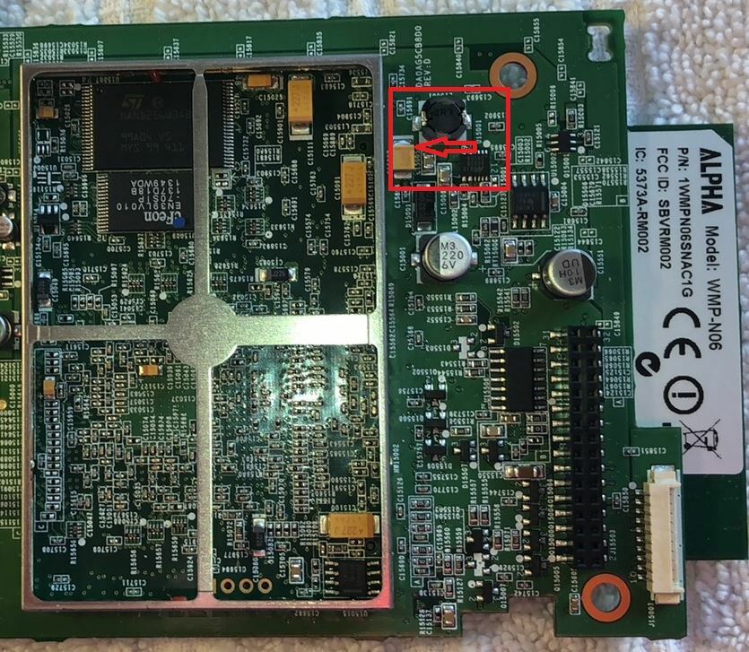
Is this the cap that you are talking about?
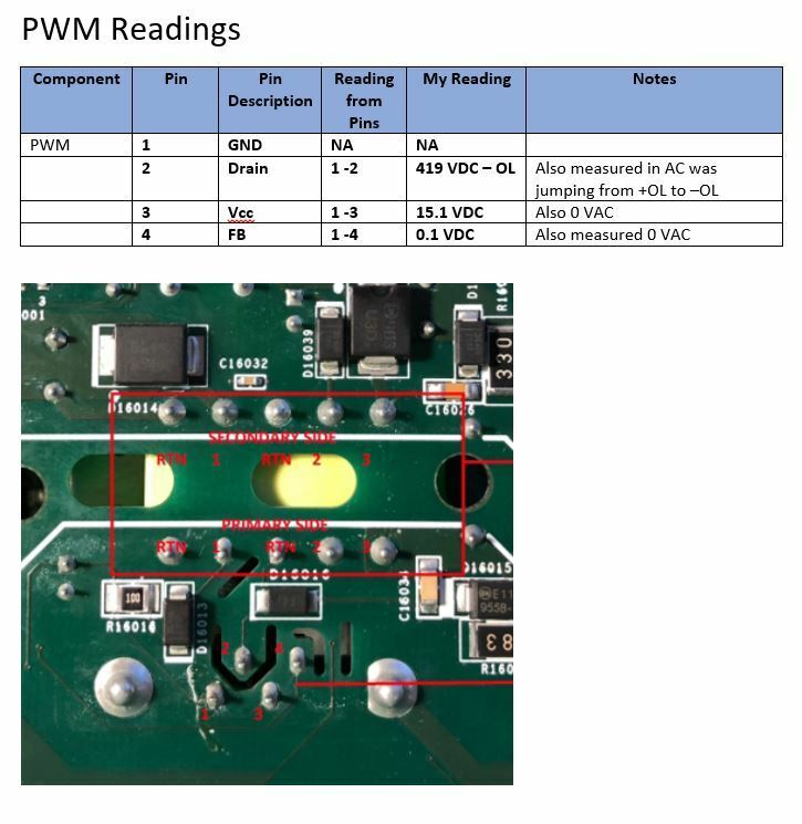
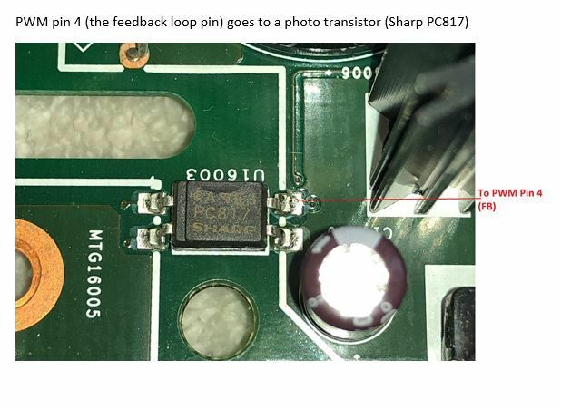
I took some more readings on the PWM this morning and I am not sure of what it means. I have 300+ VDC on Pin 2, 15 VDC on the Vcc (pin 3) , and 0 VDC/AC on pin 4 (FB). Interestingly, pin 4 connects to a photo transistor on the other side of the board. It seems to me that the PWM is energized but not getting a signal to modulate the voltage across the switching transformer. I read up on switching power supplies and it seems that the PWM needs a signal from the DC run circuit to tell it to start switching the DC across the transformer. Here are the readings I took:

Really great documentation here, well done!
Couple of observations.
-if you are getting the 3.3,8ish,15 on the secondary then the bias converter PWM is working correctly.
-The reason you are seeing 0V on the transformers pins is because you are looking at AC with your meter set to DC. Those biases measured in the logic card say to me that the bias converter is running and the output is making its way to the logic card. Good sign
-I can only think of one thing left to do, and that is measure the output of the buck converter on the bottom of the logic card. There is a inductor with a (normally) yellow electrolytic cap. Solder a wire to the striped side of the cap and put the card back in and plug in. You can put the red lead on the wire and the black one to chassis. Should have 1.5V output.
Do you know much about reading serial (UART) from a computer? You may have noticed a 4 pin header under the EMI shield that you removed. There may be some diagnostic clues coming out of that serial headder.
The one I am working currently has a confirmed good power and riser boards and shows up in the Sonos app but when you push play I get orange and white blinking leds. Wanting to read that header and see if it can give me a clue as to why mine shizes the bed when I push play.
I’m not entirely sure but I did replace it with a new one a while ago. I do have some more new ones that I can try. Do you know how I can test the PWM to see if it is good?
Are you absolutely sure that your PWM is good? What you are showing is evincing that you aren’t getting reasonable switching out of it.
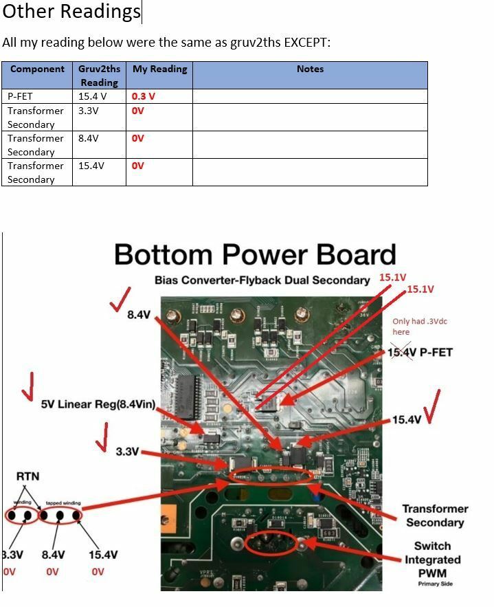
@gruv2ths - I just read you most recent PM to my questions about where to put the black lead from teh meter when reading voltages on the power supply and below are my readings. As I said before, The only readings that are different from yours are the P-FET and the secondary switching transformer. See below for pictures and explanations.
On another note, while the AMP is plugged in, there seems to be some voltage going to the logic board as I have read 5V across some of the small electrolytic caps. Also some of the chips that are under the metal housing are slightly warm to the touch. Not hot mind you, just slightly warm like you can tell voltage is applied. I am not sure what that means but I thought it was worth noting.
I seem to be a bit lost for why this thing is not working.
Here are the voltage reading pictures:
Also here are some readings from the logic board:
The RTN should be ground (1 and 3)
@gruv2ths and m0utainman - So to ask my question a different way, can you tell me what ground points you were using when you took the voltage measurements that are shown below?
Thanks m0untainman,
Yesterday I had some time and on a hunch I replaced the PWM but it did not fix the issue. I am really stumped by this but also determined to understand why it is failing and fix it 🙂 I just sent you and gruv2ths PM's asking about getting some detailed readings and what GND points you used. In some of my first posts I was using chassis as GND and I am not sure if that was correct. I would like to start over fresh and try to troubleshoot the switching power supply to see if it is working properly or not.
Also on the white LED you mentioned above, I have never really gotten the LED to shine brightly, just very (and I mean very) dimly lit.
Yeah... 0V on the secondary side of that PWM is a big red flag that the PWM is bad. On a dim bulb tester is the PWM warm? Since your dim bulb goes dark, I'm guessing its not. So far we have seen a couple of those go sour and the liquid issues that you showed could mean it got wet. It seems to be a pretty sensitive part.
That said, without that part working, you shouldn't have gotten the white light to show any color (at least that was the way it was for me).
That said, without that part working, you shouldn't have gotten the white light to show any color (at least that was the way it was for me).
Well all the parts that I ordered came in and I installed them, however I am sorry to report that the amp still did not power up. I am disappointed and perplexed at what else could be causing this. Right now, the situation does not look good.
One thing that keeps bugging me though is early on when I was measuring the voltages around the bias converter. I did not have some of the same voltages that gruv2ths said he did. I am wondering if they may still be something wrong there.
@gruv2ths and @m0untainman - Could either one of you give me some detailed readings of what you have on your functioning amps as compared to the below?


A quick update: I ordered the caps and resistors needed to replace the faulty ones. The caps are size 1206 SMD ceramic and I got 2 different values as they are not marked so I guessed (.01uf and .1uf). The resistors are marked with a "750" on them which means they are 75 ohm size 0603 SMD. After ordering the parts, I started to look around closer at the rest of the WiFi board. I took the tops off of the three metal housings on the board and found yet another burned component. This one looks like an inductor inside the metal housing closest to the original failed parts. Judging by the other comonents around it, the circuit seems to be a transceiver circuit for the Ethernet ports. I determined this by looking at the chip with the part number 78Q2123.
When I put my ohm meter on the failed inductor it read .890 M ohms. The size seems to be a 0603, but I will need to figure out the value and order one of these as well. This one is going to be very challenging to replace as it is inside the metal housing that is closest to the faulted caps and resistors. So the story continues. I am going to be really happy if replacing these parts makes this amp functional again!
When I put my ohm meter on the failed inductor it read .890 M ohms. The size seems to be a 0603, but I will need to figure out the value and order one of these as well. This one is going to be very challenging to replace as it is inside the metal housing that is closest to the faulted caps and resistors. So the story continues. I am going to be really happy if replacing these parts makes this amp functional again!
Yep... you are good. 🙂
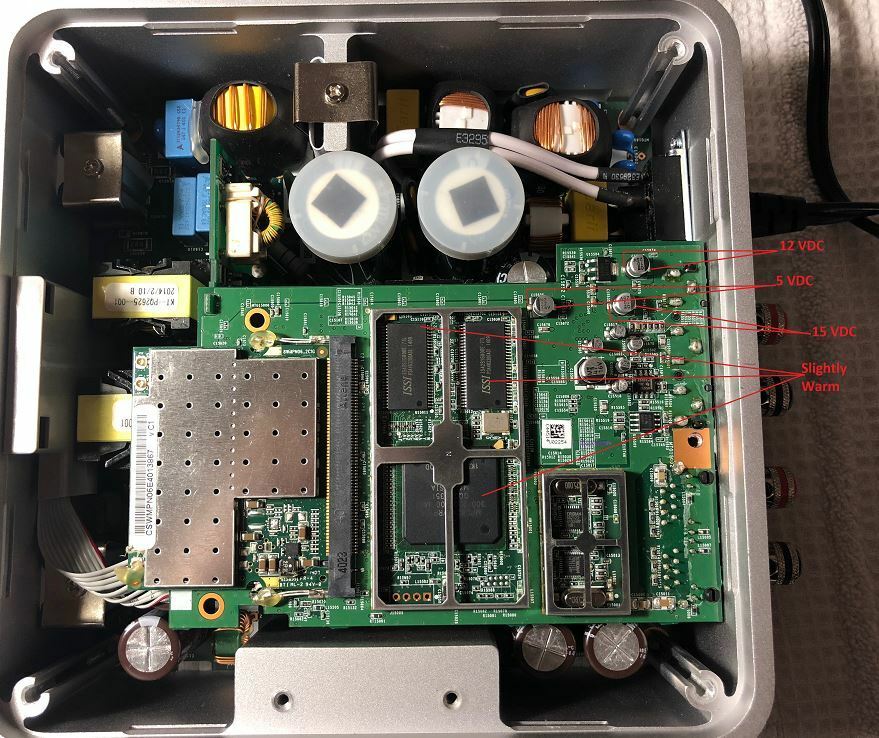
@m0untainman - RE: The caps you mentioned. I think my picture threw off your orientation. See the full sized pic below. Are those the caps you were talking about with the plastic tops?
Page 13 / 17
Reply
Enter your E-mail address. We'll send you an e-mail with instructions to reset your password.