The amp has no power. Is there an internal fuse for this unit?
Has anyone taken one apart?
Page 16 / 17

I removed the TO-220 PWM - and wouldn't you know... the bulb goes dim. 🙂 The part shows 30 ohms of continuity from pin 1 (GND) to pin 3 (Vcc) and 32 ohms from GND to pin 4 (FB). The continuity is in both directions. Based on the schematic, this part looks blown to me.
I think we may have found the culprit. Now I just need to find a replacement. It is a 5M0265R Fairchild. Looks like the replacement is a KA5M0265R.
I think we may have found the culprit. Now I just need to find a replacement. It is a 5M0265R Fairchild. Looks like the replacement is a KA5M0265R.

Your assumption seems correct. The PWM is not switching therefore no secondary voltages will show up. I would unsolder that PWM and watch the bulb go out!
If it’s too hard to get the PWM out in one piece, cut the leads and unsolder them one by one.
If it’s too hard to get the PWM out in one piece, cut the leads and unsolder them one by one.
The 2 RTN points on the transformer are showing 0L. I tried to short those too, but got nothing. Actually I am getting no power on the secondary winding (testing 1 and 2 for 3.3V and 3 and for for 8.4 volts, and 3 and 5 for 15v). They show nothing using a 60W bulb. Trying a150W bulb... more or less the same. I get some voltage on the primary (like 10v), but nothing on the secondary.
The PWM is warm so its the likeliest suspect at this stage. The PWM is HOT with the 150W bulb.
The PWM is warm so its the likeliest suspect at this stage. The PWM is HOT with the 150W bulb.
@gruv2ths thanks for jumping in! Yes... removal of that inductor was easy... putting it back wasn't. I had to get creative and solder wire patches to get it through the hole so I could solder the leads back... took quite a while.
The dim light is indeed bright. The TO-220 package (center of my photo on the heat sink) PWM gets warm for sure. I'm guessing the short is somewhere in that area. Just need to get that piece off but I dread it since it has a lot of solder points and the heath sink. I was dreading pulling that component.
Not sure how to test a PWM... I'm guessing that will take a breadboard.
Finding this short is not easy!
Great work documenting your troubleshooting and thought process. We will get good at this some day, maybe Sonos will hire us?? LOL JK
So the inductor in the upper left of your picture is the common mode inductor that is in series with the 28V supply.
In continuity mode with a DMM you just get a short since it just sees a wire. I once removed that inductor (it was a real pain getting all 4 wires back in) in an attempt to find out if my short was in the rectifier (2 diode packs clipped to the chassis) or the load. For me it was the load. One of my amp ICs was a short. That is the unit I am working currently. I will share a troubleshooting slide on the 28V supply when I get it working reliably.
I pulled the inductor and its good.... so thats not it...
A slight update... the choke filter in the upper left corner of that picture (the big one) has 4 wires. I think I have detected a short on it or something connected to it... between the primary and secondary, I get continuity with a resistance of 148 ohms. Could that be that the inductor has a short? Keep in mind it was DMM tested on board and I have not removed it.
The resistor that blows comes off the primary... so there seems to be a relation.
The resistor that blows comes off the primary... so there seems to be a relation.
Ok... I tested the thermistor and under heat etc and it seems to test out ok. Due to the excellent posts in this thread, I decided to put together a dim bulb tester so I would stop blowing components. Great idea...
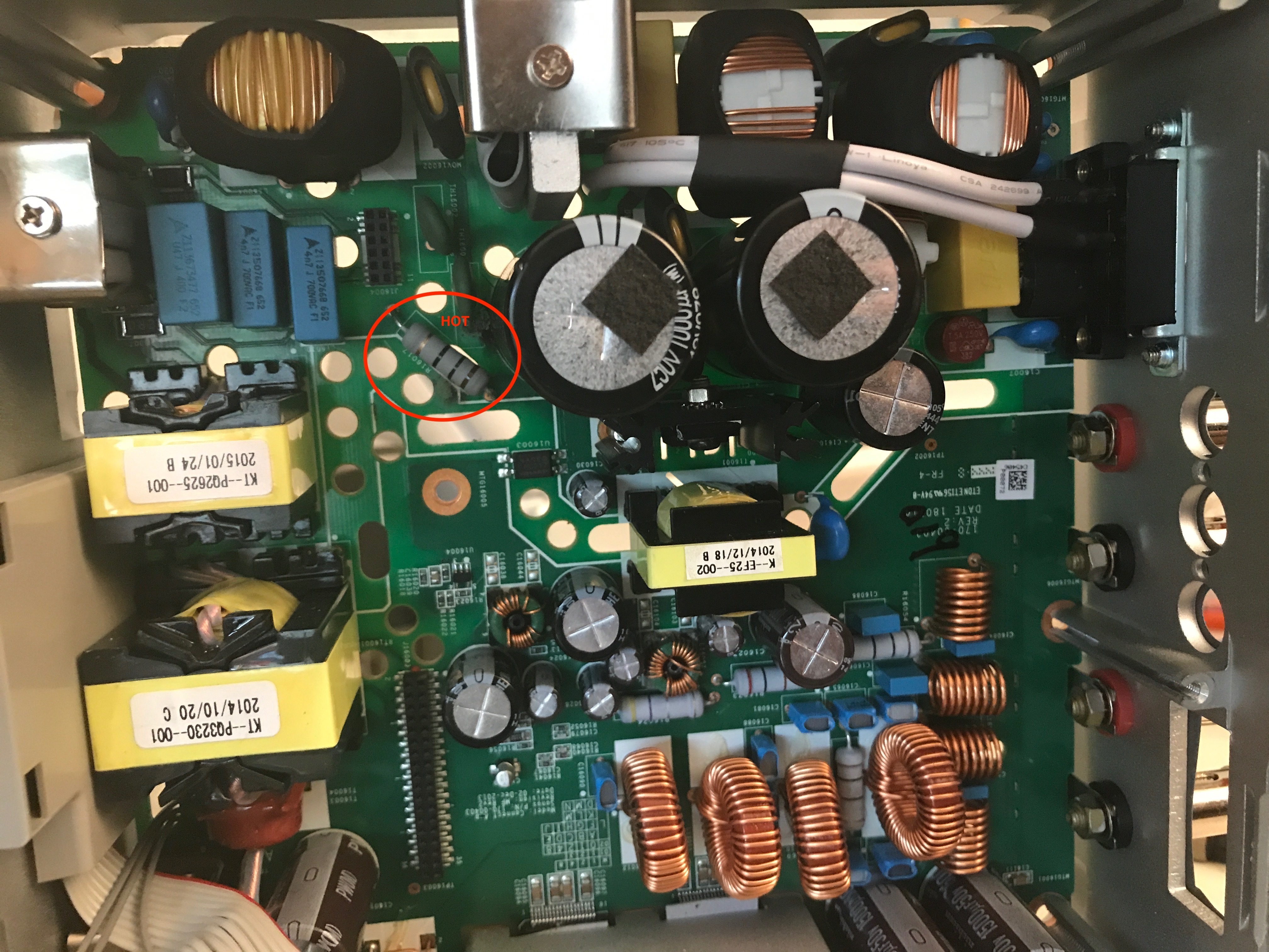
So I decided to fire it up under the dim bulb tester after replacing the 10 ohm resistor and putting back the thermistor... and the light bulb shined brightly so I still have a short somewhere....
I cut the power and decided to test for heat. Again, that resistor was getting hot (and was saved due to the dim bulb tester).
Here is the resistor and it is hot (notice the circle labeled hot):
Anyone have ideas on how to hunt down the short?
Slight update... as I am waiting for the SCK054s from China... I decided to check everything in the path. All looked good except for the 115/220 red switch. It showed 0L on the meter at 115. I switched it to 220 and it was 0L. Switched back to 115 and had continuity. My guess is when the unit got wet, something happened to that switch and hence it made the unit look like it was supposed to be connected to 220v. I followed the trace and with 220v, it all leads to the blown resistor and thermistor. But with 115 active (continuity) it throws in a drop through the varistors and the other path meets it. Just a guess, but it appears that the 220v setting may have caused the current consumption along the resistor/thermistor path to exceed what it was normally supposed to see. That may be a red herring and I will find out when my thermistors arrive... but I thought the 220v setting running on 115v wouldn't hurt the PS...worst case it just wouldn't fire up. I'm just guessing that perhaps it does indeed have an impact on a PS.
@gruv2ths - Outstanding job. I have a SONOS ZP120 that unfortunately got wet and the power blew a 10ohm 2W resistor (R16017). I replaced it. I plugged it in and that resistor blew again... and it looks like it took out one of the SCK054 thermistors (TH16001). The thermistor was a wee bit charred however it tested 5ohms which is the normal rating. I have ordered new ones since I don't trust anything that got charred, but they will take 10-4 days to get from China... nobody sells em here in the US.
I tested the rectifier on the input side (the one clamped to the chassis) and it looks good. I tested the diodes and those look fine. All caps are looking good too. The fuse is fine... it never blew.
I am guessing the problem lies downstream from the components listed above. A couple of questions...
1 - That TO-220 you mentioned... is that the one that has a heatsink screwed into it and standing up? Do you know the code on it or type as I cannot tell.
2 - What is the secondary rectifier your are referring to? I would like to test mine to see if its checking out (or not).
If you have any recommendations, I would love to know how to any techniques are parts I should be checking on the PS board... I am thinking this is simple... but I am having a tough time narrowing it down.
Thanks!
For your Information:
Sonos products are not designed to be opened and repaired out in the world, and we do not provide any resources or replacement components for doing this. The warranty services for Sonos components also does not cover units that have been opened in any way.
Even if your player is outside the standard warranty time, we can probably still assist with a replacement as long as it hasn't been opened. There will likely be a fee for the replacement if it's out of warranty.
Anytime a unit fails, we want them to come back to us when possible so that we can review what happened and make adjustments if there's need.
Is there any YouTube video that shows how to replace the fuse ? Pls add the link - Tnx
So as promised above I have repaired my new ZP120, and another 120.
The first one:
Just the input bridge rectifier has a shorted diode that blew the fuse. Once the bridge was replaced it has worked fine.
Second one:
SOmetimes it came up no led, totally dead, other times it came up and would get 1/2 way through setup before crashing my network.
Noticed a primary side 350V 33uF electrolytic cap was toast. Replaced It and nothing really changed.
This one was a real head scratcher. The blown cap belonged to what appeared to be power converter circuit that provides biases around the board. Noticed that the GND test point had no continuity to the outputs of the tapped winding. I probed a good working ZP120 and found that all of the outputs of the bias converter were grounded together. So I shorted the return of the tapped winding(8.5V and 15V outputs) to the return of the single winding (3.3V output). Was nervious to power it back up, so just in case i used the dim bulb and it worked great. Replaced the dimbulb with the fuse and I am in business.
I did a chart so my crappy memory will have some help next time i tange with a ZP100. See below.

The fuse is a small orange cylindrical part by the input connector. Through hole, axial lead. I wouldn't just swap it out, it will blow again. If you comfortable around high voltage, I would try the dim bulb.
Dose any one know where is the fuse ?
Has anyone taken one apart?
I repaired the one I am using. It was a no power failure as well. It appeared to have some sort of liquid damage on the logic board that shorted an output of the power supply. I fixed that damage on the logic board, then started looking through the power supply. What I found was a TO-220 (or similar) package dual schottky rectifier was now shorted, also the main bridge rectifier on the front end of the power supply was also a short. Once replacing those 2, the dim-bulb went bright then dim and the indicator started flashing. And I friends was in business!
I liked the ZP120 described above so much that I just bought another ZP120 with the same fail description. I crack it open tonight. Will update this forum when I get it working.
I liked the ZP120 described above so much that I just bought another ZP120 with the same fail description. I crack it open tonight. Will update this forum when I get it working.

No updates. Keep us posted on your repair efforts.
Any new updates? I just bought a dead ZP120 on eBay and will be diving into it next week.
I don't have any updates. I put my repair on hold until I can find someone who has had more time than me and who has created a schematic of at least the power supply section. Alternatively I'm keeping my eyes open for an inexpensive used ZP120 so that I can use it as a reference for the correct voltages and therefore to trouble shoot my nonworking unit..
Piperdog, Any chance you've got any updates? I'm in the same situation.
Userlevel 2
I decided to skip the dim bulb tester although I'll keep it in mind for the future. I replaced the 2 thermistors, 2 varistors and 5A fuse in the power supply section and applied power. The good news is nothing shorted out. The bad news is that some component must be open downstream because I'm not getting voltages where I should. I wish I had a schematic. It would be so easy now to trouble shoot with it. Or another good unit to compare voltages.
Google Dim Bulb Tester for a simple, low cost way to protect devices that may still have issues...
Userlevel 2
I didn't realize that it would be that inexpensive for Sonos to repair an out of warranty unit. Thanks for the info. Unfortunately they may not touch my unit now that I've opened it up. At any rate, I received replacement fuses, varistors and thermistors today from Digikey. If things work out I'll post the Digikey part numbers. Now I have to find time to install them. Hopefully they are all that is required but of course there is a reasonable chance that something else is wrong with the power supply causing these parts to fail. I'll know soon.
You could have sent it in for replacement for a modest cost. I sent back a ZP100 for around $150. SONOS sent me back a brand new ZP120.
Page 16 / 17
Reply
Enter your E-mail address. We'll send you an e-mail with instructions to reset your password.