Play:5 Gen1 no power, 2QS02 driver IC issue

  • 10 January 2021
  • 5 replies
  • 360 views

Badge
Play:5 2QS02 Picture is from another community member

Hello,

I started this specific topic on the 2QS02 power mosfet driver because maybe someone figured this out already.

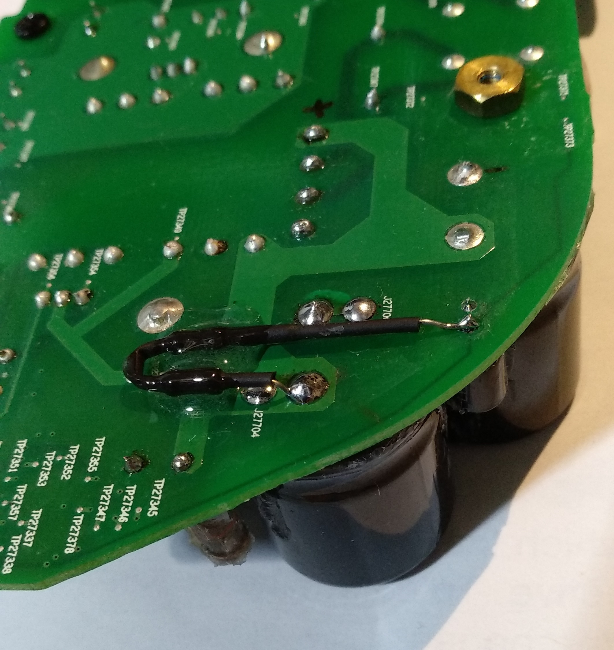
The “no power” issue is related in my case by the lack of Vcc voltage on pin7 on this driver IC 2QS02, as in the respective Infineon datasheet.

If I manually apply 12V on pin 7 then all is good, the power comes back in the secondary. At least it means there is nothing wrong with the IC.

I know, I could power the driver IC externally, right? But then it will not be Sonos anymore…

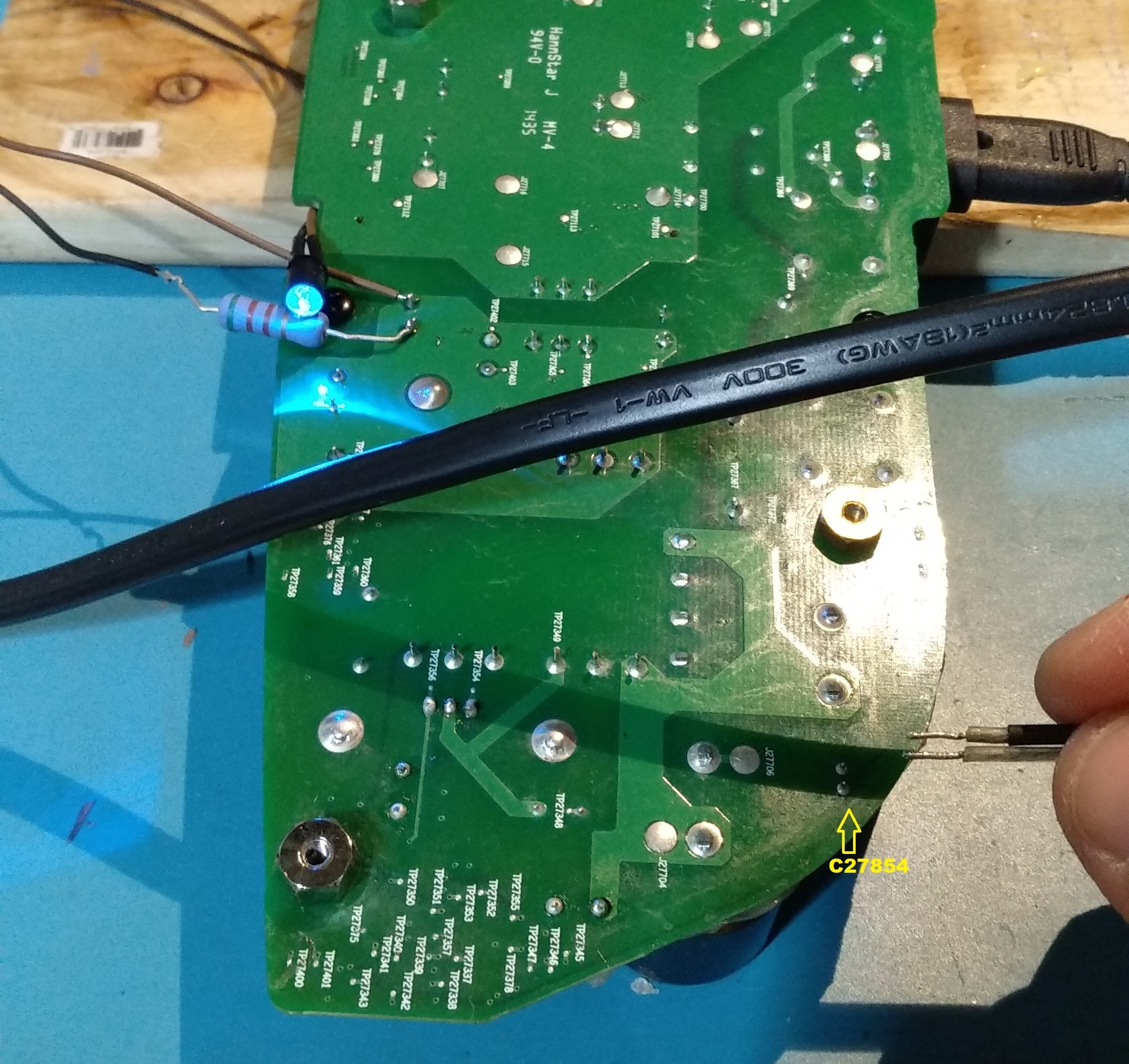
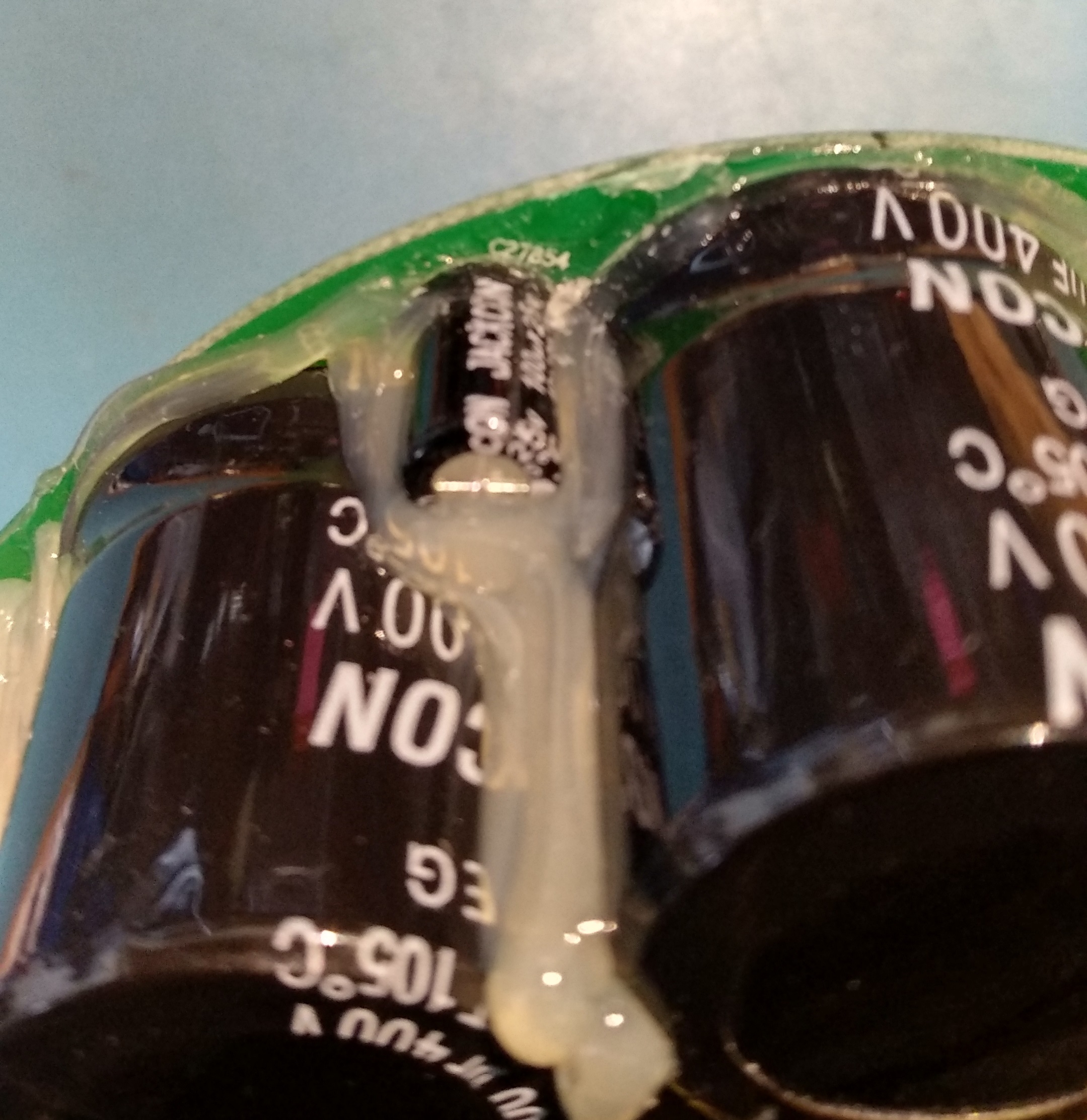
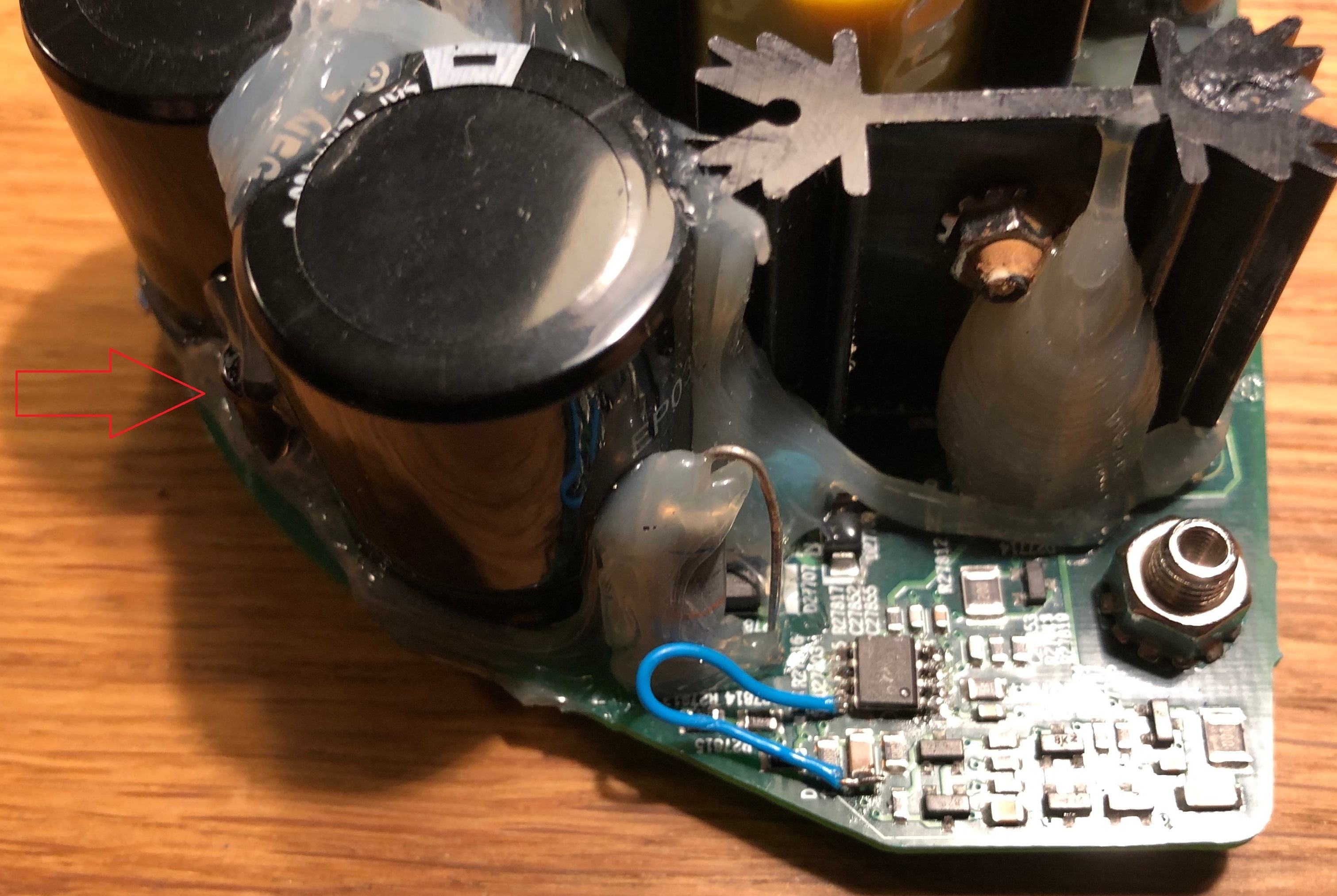
The supply voltage of this IC is related with that small 100uF 25V small capacitor located between the two big main 400V ones. I cannot see from where that 100uF capacitor is being charged, to be able to supply the power to 2QS02. There is anyone who figure-it out this part of the power circuit?

Thanks


This topic has been closed for further comments. You can use the search bar to find a similar topic, or create a new one by clicking Create Topic at the top of the page.

5 replies

Badge

As an update, I was able to “jumpstart” C27854 (the small one) with 20V (as someone mentioned in this forum that this is the voltage that it’s “normal” in operation), as a result, the power goes on, - see the blue LED turning on, hooked on the +12V rail- and it stays on.

The voltage on C27854 is around 13V, and stays there. This is probably some secondary charging circuit from the fly back transformer. But is never reaching up to the 20V, proving that the primary charging circuit is not adding up his contribution to the C27854 voltage.

Still, the mystery of the primary power for the 2QS02 driver chip is not solved.

Anyone figure this out?

Userlevel 5
Badge +16

 Hi @dvd4me

Welcome to the Sonos community and for letting us know about your concern. Let me help you with this.

We respect that you wanted to replace your Sonos Play 5 motherboard, but it is not recommended that you perform it on your own, it may cause potential danger to you. As our first priority is always the safety of our customers. I recommend reaching out to our phone support team for further assistance and to check out of warranty and loyalty program options to provide the best recommendations regarding this concern. Our phone support team is closed during weekends but you may reach them from Monday through Friday, 10 am - 7 pm EST.

If you have any questions or run into any other issues, please do not hesitate to contact us, we’ll be glad to assist you.

Badge

I have-it fixed finally but I do not know the cause. Here it is in words and pictures:

First, small cap (C27854) is not charging from the AC side, those are probably discharge resistors to the remaining capacity in the filtering caps. It’s another mechanism I could not figure out. The C27854 is providing power to the ICE2QS02 driver chip. It goes thru all those small diodes and caps on the edge of the board. The normal behavior on the voltage for C27854 is that is charging up to around 20V slowly and then ( some of those diodes and transistors do that) turns on the power on the ICE2QS02. 

Once the chip is starting the voltage is self sustaining to around 13 V, I do not understand from where, maybe from the fly back transformer winding itself. 

So for me the challenge was to produce the charging of the C27854 up to 20 to start up the IC. I did this by putting 2 390Kohm from the + on the big caps. I monitor the voltage and it’s ramping up slow, like a second or two. After it reaches 20V the IC starts and it self sustain to 13V. It’s 3 days already and still works! meaning there is no other fail. There was no problem in the fuse or rectifier, nothing burned. As you can see the LED turns on with the 2 resistors soldered. This is the story of this fix.

the 2 resistors
Led turns on now!

Regarding the kind offer from the lady to “replace the motherboard” there is no way I would pay for something like this. All the “Green planet” groups would agree reusing something is better than recycling or dumping ( think about the empty water bottles in the oceans).

So the reason “for my own safety” is just a reframing of the idea they do not want people to fix devices themselves, their argument is placed in such way that it mimics as they show care for the customer.

A real “customer care” would be to provide the schematic of such old device, at least the part that is failing mostly.

Many people save TV’s from going to dump because of bad LED or other type of failures. And the manufacturer “leaks” the service manuals… smart guys, they promote the culture of reusing, yeah, reusing…

By the way, this Play 5 sounds great! I never had a Sonos before and the sound quality is amazing.

I reset-it and using the app to set-it up, so I can stream to it. So cool!


On the contrary, by not providing schematics of their electronics, as well as enforcing the ‘no warranty after they’ve been opened’ rules, I expect they are strengthening their legal position against the inevitable lawsuit when someone not familiar with working with electronics opens one up, and electrocutes themselves…

It would be nice if they were to provide a repair service, though. But then again, look at Apple’s ongoing relationship with third party repair vendors for their iOS devices. Rocky at best. 

Badge

Again, this is not hospital or home critical life support equipment, going on this way of seeing things, imagine you can get hurt by changing your winter tires or break pads, so many sharp objects, or hurting your back… Falling of your bike or skateboard… God forbids...  Life tends to be generally life-threatening… right?

I tend to believe that this is just scarecrow, for whatever reason they might have… Why? Not so many manufacturers protect their product internals based on this reason “for your own safety”.

If someone can use this bits of information to fix these things even better. This is help for the community, for the planet and not for the company as is.